background image


20

11. Warranty 

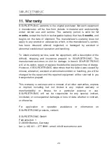
SOURCETRONIC warrants to the original purchaser that each equipment 
it  manufactures  will  be  free  from  defects  in  material  and  workmanship 
under  normal  use  and  service.  The  warranty  period  is  valid  for 

12 

months

, except the built-in rechargeable battery that has 

6 months

, and 

begins  on  the  date  of  shipment.  The  manufacturer’s  warranty  does  not 
apply to any product or accessories which, in the manufacturer’s opinion, 
has  been  misused,  altered,  neglected,  or  damaged  by  accident  or 
abnormal conditions of operation and handling. 
 
To obtain warranty service, send the equipment, with a description of the 
difficult,  shipping  and  insurance  prepaid,  to  SOURCETRONIC.  The 
manufacturer  assumes  no  risk  for  damage  in  transit.  SOURCETRONIC 
will, at its option, repair or replace the defective equipment free of charge. 
However, if SOURCETRONIC determines that the failure was caused by 
misuse, alteration, accident or abnormal condition or handling, you will be 
charged for the repair and the repaired equipment will be returned to you 
transportation prepaid. 
 
This warranty is exclusive and is instead of all other warranties, express 
or  implied,  including  but  not  limited  to  any  implied  warranty  or 
merchantability  or  fitness  for  a  particular  purpose  or  use. 
SOURCETRONIC  will  not  be  responsible  for  any  special,  indirect, 
incidental, or consequential damages or loss of data, whether in contract, 
or otherwise. 
 
For  application  or  operation  assistance  or  information  on 
SOURCETRONIC products, contact: 
 
SOURCETRONIC GmbH


Fahrenheitstr. 1
D-28359 Bremen, Germany 
fax: (+ 49) 421 – 277 9998 - email: [email protected] 


Summary of Contents for 61242

Page 1: ...Formato 137mm x 190mm High frequency earth tester User guide Technical specifications ...

Page 2: ...3 TM 25R High frequency earth tester User guide GU 1535 ...

Page 3: ...egulations for these matters This equipment should be used only by a trained and competent person strictly applying suitable safety rules Used symbols Caution refer to User Guide Equipment complies with current EU Directives The rubbish bin with a line through it means that in the European Union the product must undergo selective disposal for the recycling of electric and electronic material in co...

Page 4: ...Selecting the type of measurement 13 6 1 1 Grounding resistance measurement 13 6 1 2 Grounding resistance measurement function with inductive component compensation 13 6 2 Looking for the potential profile flat area 15 6 3 Guard wire inductance 15 7 Abnormalities indications on the display 16 7 1 Excessively high earth resistance 16 7 2 Excessively high resistance in the auxiliary rods 16 8 Auto p...

Page 5: ...ETRONIC TM 25R grounding resistance tester for high frequency has been developed This is the appropriate tool for a fast safe and reliable grounding resistance measurement in each tower of a working line transmission without disconnecting the ground wire Its operation is based on the use of a high frequency measurement current 25 kHz for which ground wire inductive impedance taking into account a ...

Page 6: ...ent has a Bluetooth communication interface that allows remote operation through a Tablet running the BlueLogg application With it you can save photos of the towers and the GPS coordinates of each Also allows you to record voice annotations to each measurement TM 25R is powered by a built in rechargeable battery It is a rugged easy to carry resistant to the hard weather and geographical features o...

Page 7: ... by the operator The following graphics show the function of each one of the equipment s items 2 1 Connections and items Earth Resistance f 25kHz 2 08 2013 17 21 Power supply input USB interface Current rod connector Potential auxiliary rod connector Tower support rod connector Display Keyboard On Off switch Thermal printer ...

Page 8: ...it activates the display light After 10 seconds the backlight will auto turn off in order to save the battery charge It selects the grounding resistance measurement function with inductive component compensation It indicates selected function It selects grounding resistance measurement function without compensation It indicates selected function The START key Starts the test A measurement is runni...

Page 9: ... Full charge LOW BATTERY 2 08 2013 17 21 ή Battery Status 2 08 2013 17 21 ίίί Battery Status 2 08 2013 17 21 ίίίίίίίί 3 1 3 Recharge procedure This equipment has an internal battery charger with a smart circuit which adjusts the battery charge to the optimized parameters to ensure the maximum service life To recharge the battery Check if the TM 25R is off and then connect it to the 110 V or 220 V ...

Page 10: ...s of the last test ATTENTION Don t pull the paper The printer can be easily damaged This printer uses 57 mm wide thermal paper Pull the lever located on the lid Insert the paper reel as shown in the figure Keep the tip of the paper out of the printer and close the lid ...

Page 11: ...ne with the tower point zero of measurements perpendicular to the power transmission line Initially the auxiliary current rod must be at a 100 m distance and the probe potential rod at a 65 m distance In order to establish a connection with the farthest rod a black cable must be used together with the shielded cable black that must be connected to the equipment to the H connector The central rod p...

Page 12: ...nductive component compensation Select the function measurement with compensation by pressing the key Press the key to start the measurement The led of the key will turn on and after a few seconds the display will show the resistance with no compensation value The compensation process starts immediately During this process the display shows capacitance values that the system selects and the Rc val...

Page 13: ...ms is not significant this will be shown in the display R 9 04 Rc ___ Ω C ___ L 0 H 01 01 2014 17 21 μ If the test is printed the message Undefined for the values Rc and C with L 0 will be displayed TM25R XX0000X TEST 00140 01 01 2014 17 21 Rc Undefined C Undefined L 0µH _____________________ R 7 53Ω ...

Page 14: ...in the potential profile flat zone Rv in the above mentioned picture If 3 measurements with the same value or with an acceptable mistake made by the operator could not be obtained 5 is an usual acceptable value current electrode distance must be increased in for example 50 meters and several measurements should be taken again with the probe until finding the potential profile flat zone Check alway...

Page 15: ...ason may be a wrong connection or excessive high diffusion resistance on the H pole Check the installation to correct the problem If the problem is being caused by excessive resistance watering the rods or inserting several interconnected rods may reduce the resistance allowing measurements to take place correctly Also check battery charge status IMPORTANT Take into account that if the grounding r...

Page 16: ...nt in the PC run the executable usb install exe and click in Install USB Drivers Installer Welcome to the USB Setup program This program will install the USB drivers required to establish the communication between your computer and test equipment It is strongly recommended that you exit all other programs before running this Setup program Cancel Install 9 2 ST Logger software This software makes c...

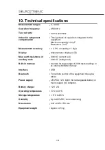
Page 17: ...LCD Max earth resistance of auxiliary rods 2000 current rod 2000 voltage rod Built in memory It allows for the storage of 2000 tests readings in its internal NVRAM memory Interface USB Bluetooth For remote control of the equipment through a tablet Power supply LiFePO4 12 V 6000 mA rechargeable battery or mains supply AC Adapter Battery charger 12 V 2 A Operating temperature 5 C to 50 C Storage tem...

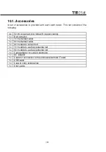
Page 18: ...pper coating 1x Rod extractor 1x 70 m shielded cable 1x 50 m shielded cable 1x 30 m cable to current rod 1x 70 m cable to auxiliary potential rod 1x 50 m cable to auxiliary potential rod 1x Cable adapter for current electrode 1x AC Adapter 1x Cable for connection to the unknown electrode Tower 1x USB cable 1x Case to carry accessories 1x User guide ...

Page 19: ...no risk for damage in transit SOURCETRONIC will at its option repair or replace the defective equipment free of charge However if SOURCETRONIC determines that the failure was caused by misuse alteration accident or abnormal condition or handling you will be charged for the repair and the repaired equipment will be returned to you transportation prepaid This warranty is exclusive and is instead of ...

Page 20: ...21 Notes ...

Page 21: ...22 Notes ...

Reviews: