Read carefully before installation, commissioning and operation
Pool Controller
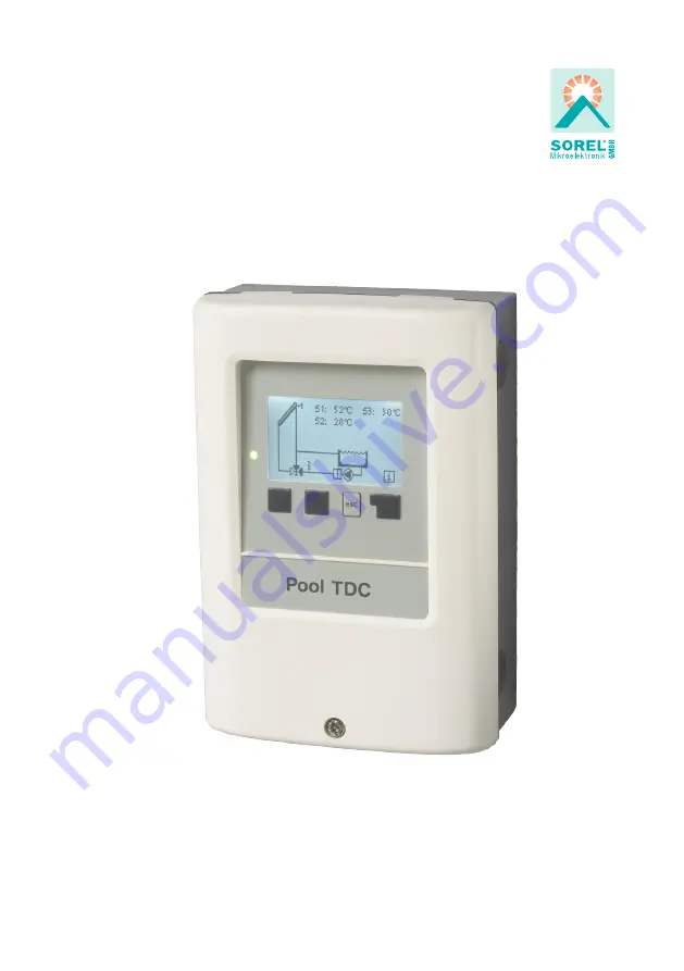
Pool TDCM+
Installation and operating instructions
Page 1: ...Read carefully before installation commissioning and operation Pool Controller Pool TDCM Installation and operating instructions...
Page 2: ...ic overview 16 2 5 Message log 16 2 6 Reset clear 16 3 Display mode 17 3 1 Schematic 17 3 2 Overview 17 3 3 Alternating 17 3 4 Sleep mode 17 4 Operating mode 18 4 1 Automatic 18 4 2 Manual 18 4 3 Off...
Page 3: ...applicable DIN EN standards and the installation and operating instructions of the additional system components must also be observed The con troller does not under any circumstances replace any safet...
Page 4: ...anges to the unit can compromise the safety and function of the unit or the entire system Danger The controller has been manufactured and tested with regard to high quality and safety requirements The...
Page 5: ...sible ambient conditions Ambient temperature for controller operation 0 C 40 C for transport storage 0 C 60 C Air humidity for controller operation max 85 rel humidity at 25 C for transport storage no...
Page 6: ...etc Individual configuration of special functions Extensive menu settings with explanations Menu block activation to prevent unintentional setting changes Resetting to previously selected values or fa...
Page 7: ...additional system components and safety components may be required such as check valves non return valves safety temperature limiters scalding protec tors etc and must therefore be provided Pool with...
Page 8: ...doing so 4 Hold the lower part of the housing up to the selected position and mark the 3 mounting holes Make sure that the wall surface is as even as possible so that the housing does not become dist...
Page 9: ...ng Follow the protective areas to German Institute for Standardization VDE 0100 702 for the installation of the control distances to Schuztbereich 0 and 1 Achtung Electric shock danger by improper con...
Page 10: ...rs The temperature sensor cables must be routed separately from mains voltage cables and must not for example be routed in the same cable duct The controller operates with PT1000 temperature sensors w...
Page 11: ...r N L Mains phase conductor L N Mains neutral conductor N R2 Ball valve heat pump or auxiliary pump R2 Ball valve The PE protective conductor must be connected to the PE metal terminal block max 12 V...
Page 12: ...er Z 1 Inputs are made with 4 buttons 3 4 which have different functions depending on the context The esc key 3 is always used to cancel or exit a menu If applicable there will be a request for confir...
Page 13: ...at the selected setting again or adjust it if desired Pressing the esc key more than once takes you back step by step to the selection mode thus cancelling the commissioning help Finally the menu 4 2...
Page 14: ...lana tions Function control of the system with operat ing hours etc Automatic mode manual mode or switch unit off Set parameters needed for normal opera tion Frost protection anti seizing protection e...
Page 15: ...small deviations in the measurement values In this case the display values can be compensated for by making entries on the controller Follow the instructions under 7 3 Sensor calibration on page 23 W...
Page 16: ...ata Statistics 2 1 Operating hours Display of operating hours of the pump connected to the controller various time ranges day year are available Displays the average pool temperature 2 2 Average pool...
Page 17: ...hics mode the selected hydraulic systems are depicted with the measured temperatures and operating states of the connected consumers 3 2 Overview In overview mode the measured temperatures and operati...
Page 18: ...and thus the connected consumer are switched on and off with no regard to the current temperatures and the parameters which have been set by pressing a key The measured temperatures are also shown to...
Page 19: ...ions are also met then the controller switches the associated pump and or ball value on If the temperature at sensor 1 drops below this value by 5 C the pump and or the valve are switched off again Se...
Page 20: ...running Setting range 0 30 min Default 1 min When all switch on conditions are met to activate the pump the pump is not switched on for the time set here This prevents that on cloudy day the pumps tur...
Page 21: ...hour Default daily 0 00 23 59 hour Used to ensure that the filter system is at least running for the time set here regardless of temperature Eco mode The time the filter pump was running on this day i...
Page 22: ...the cold season obsolete Observe the operating instructions for the other system components A two stage frost protection function can be activated In stage 1 the controller switch es the pump on for...
Page 23: ...unpre dictable errors Caution This menu is used to set the current time and date 7 2 Time and date For analysis of the system data it is essential that the time is set accu rately on the controller P...
Page 24: ...back to the selection mode thus cancelling the commissioning help See also E 2 7 4 Commissioning Caution May only be started by a specialist during commissioning Observe the explanations for the indiv...
Page 25: ...occur Example Displayed collector temp 40 C measured flow temp 39 C displayed stor age temp 30 C measured return temp 31 C means a setting of 20 Displayed T 10 K actual T 8 K 20 correction value Heat...
Page 26: ...Display mode 7 2 Time and date 8 Menu lock 9 Service values To lock the other menus select Menu lock on To enable the menus again select Menu lock off Setting range on off Default off Menu lock Theme...
Page 27: ...remote diagnosis by a specialist or the manu facturer in the event of an error etc The menu can be closed at any time by press ing the esc key Service values 9 Service values Caution Enterthevaluesat...
Page 28: ...Language can be used to select the language for the menu guid ance This is queried automatically during initial commissioning The choice of lan guages may differ however depending on the device desig...
Page 29: ...nger flashes To obtain more detailed information on the error press the key under the warning or info symbol Possible error messages Notes for the specialist Sensor x faulty Means that either the sens...
Page 30: ...ck it Replace the faulty fuse with a new one locate the external source of the error e g pump and repair or replace it Then recommission the controller and check the function of the switch outputs in...
Page 31: ...nce after commissioning has been successfully completed In the event of uncertainty as to the control response or malfunctions the service values are a proven and successful method for remote diagnosi...
Page 32: ...est possi ble care the possibility of incorrect or incomplete information cannot be excluded Subject as a basic principle to errors and technical changes Hersteller SOREL GmbH Mikroelektronik Reme Str...