background image

Cha

p

te

r 7  

 Men

u

 Dis

pla
y

s

 and

 Det

a

iled Se

tt

ing
s

126

7-2 Status Display on the Viewfinder Screen

7-2-2 Selecting the Display Items

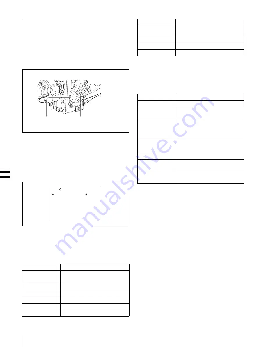
To select the items to be displayed on the viewfinder 
screen from the VF DISP 1 and VF DISP 2 pages of the 
USER menu, turn on or off the indication next to each 
item.

To select the items to be displayed on the viewfinder 
screen, proceed as follows.

1

Set the MENU ON/OFF switch to ON.

The last accessed menu page appears on the 
viewfinder screen.

2

Turn the MENU knob until the VF DISP 1 or VF DISP 
2 page appears, and press the MENU knob to select the 
page.

VF DISP 1 page

You can select the following items to be displayed on 
the screen on the VF DISP 1 or VF DISP 2 page.

VF DISP 1 page

1) The viewfinder display can be also turned on or off by using the DISPLAY 

switch on the viewfinder.

2) For detailed information on the display mode, 

see 7-2-3 “Display Modes 

and Setting Change Confirmation/Adjustment Progress Messages” on 
page 127

.

VF DISP 2 page

1) When an Anton Bauer Intelligent Battery System or the BP-IL75/GL95/

M100 battery pack is used, the setting of this item determines the display 
as follows.

INT:

 The remaining battery capacity is shown as a percentage when there 

is a change, and when the capacity is low.

AUTO:

 The remaining battery capacity is shown as a percentage, except 

that when this is impossible the battery voltage appears.

VOLT:

 The battery voltage is shown.

3

Turn the MENU knob to move the 

b

 mark to the item 

you want to set, and press the MENU knob.

The 

b

 mark on the left of the selected item changes to 

z

 mark and the 

z

 mark on the left of the setting 

changes to a ? mark.

4

Turn the MENU knob to select whether the selected 
item should appear in the viewfinder display (the 
“ON” setting), or not appear (the “OFF” setting), and 
press the MENU knob.

The 

z

 mark changes to a 

b

 mark and the ? mark 

changes to a 

z

 mark.

Note that pressing the CANCEL/PRST / ESCAPE 
switch to CANCEL/PRST on this page has no effect.

Item

Description

VF DISP

Turning on or off the viewfinder 
display 

1)

VF DISPLAY MODE Selecting the display mode 

2)

DISP EXTENDER

Extender indicator

DISP FILTER

Types of the ND filter

DISP WHITE

White balance memory indicator

DISP GAIN

Gain indicator

CANCEL/PRST / 
ESCAPE switch

MENU ON/OFF switch

MENU knob

 U04  VF DISP 1

 VF DISP         :     ON

 VF DISP MODE    :      3

 DISP EXTENDER   :     ON

 DISP FILTER     :     ON

 DISP WHITE      :     ON

 DISP GAIN       :     ON

 DISP SHUTTER    :     ON

 DISP AUDIO      :     ON

 DISP DISC       :     ON

 DISP IRIS       :     ON

DISP SHUTTER

Shutter speed and ECS mode 
indicator

DISP AUDIO

Audio level indicator

DISP DISC

Remaining disc capacity indicator

DISP IRIS

Iris opening indicator 

Item

Description

DISP ZOOM

Zoom position indicator

DISP COLOR 
TEMP.

Displays the color temperature.

DISP BATT 
REMAIN

1)

Displays the battery voltage/
remaining capacity of an internal 
battery pack or an external battery 
connected to the DC IN connector.

DISP DC IN

Displayed when the power is supplied 
from an external battery connected to 
the DC IN connector.

DISP 16:9/4:3 ID

Displays the 16:9/4:3 mode indicator.

DISP WRR RF LVL

Displays the reception level of the 
wireless microphone.

DISP TIME CODE

Displays the time code.

DISP REC FORMAT Displays the recording format.

Item

Description

Summary of Contents for XDCAM PDW-510

Page 1: ...glish 1st Edition Revised 5 The supplied CD ROM includes operation manuals for the PDW 510 510P 530 530P Professional Disc Camcorder English Japanese French German Italian Spanish and Chinese versions in PDF format For more details see 1 4 Using the CD ROM Manual on page 18 ...

Page 2: ...ing to qualified personnel only CAUTION The use of optical instruments with this product will increase eye hazard CAUTION Use of controls or adjustments or performance of procedures other than those specified herein may result in hazardous radiation exposure VAROITUS LAITTEEN KÄYTTÄMINEN MUULLA KUIN TÄSSÄ KÄYTTÖOHJEESSA MAINITULLA TAVALLA SAATTAA ALTISTAA KÄYTTÄJÄN TURVALLISUUSLUOKAN 1 YLITTÄVÄLLE...

Page 3: ...s or the Electronics Industries Alliance www eiae org http www eiae org For the customers in the USA and Canada RECYCLING LITHIUM ION BATTERIES RECYCLING NICKEL METAL HYDRIDE BATTERIES For the customers in Europe This product with the CE marking complies with the EMC Directive 89 336 EEC issued by the Commission of the European Community Compliance with this directive implies conformity to the fol...

Page 4: ...E émise par la Commission de la Communauté européenne La conformité à cette directive implique la conformité aux normes européennes suivantes EN55103 1 Interférences électromagnétiques émission EN55103 2 Sensibilité électromagnétique immunité Ce produit est prévu pour être utilisé dans les environnements électromagnétiques suivants E1 résidentiel E2 commercial et industrie légère E3 urbain extérie...

Page 5: ... Augenschäden VORSICHT Bei Betätigung von Bedien und Einstellteilen oder Ausführung von Bedienvorgängen die nicht ausdrücklich in dieser Bedienungsanleitung aufgeführt sind droht u U die Einwirkung gefährlicher Laserstrahlung GEFAHR Bei geöffnetem Laufwerk und beschädigter oder deaktivierter Verriegelung tritt ein unsichtbarer Laserstrahl aus Direkter Kontark mit dem Laserstrahl ist unbedingt zu v...

Page 6: ...rumenti ottici con questo prodotto aumenta il rischio per la vista CAUTELA L uso di comandi o regolazioni o l esecuzione di procedimenti diversi da quelli specificati in questo manuale possono causare esposizione a radiazioni pericolose Per i clienti in Europa Questo prodotto recante il marchio CE è conforme sia alla direttiva sulla compatibilità elettromagnetica EMC 89 336 CEE emesse dalla Commis...

Page 7: ...tos ópticos con este producto aumentará el peligro a los ojos CAUTION La utilización de controles o ajustes o la realización de procedimientos no especificados aquí pueden resultar en la exposición a radiación peligrosa Para los clientes de Europa Este producto cumple con las directivas de compatibilidad electromagnética 89 336 CEE de la Comisión Europea El cumplimiento de estas directivas implica...

Page 8: ...8 ...

Page 9: ...5 3 1 3 Write Protecting Discs 45 3 1 4 Loading and Unloading a Disc 46 3 1 5 Formatting a Disc 47 3 1 6 Handling of Discs When Recording Does Not End Normally Salvage Function 47 3 2 Recording 49 3 2 1 Basic Procedures 49 3 2 2 Deleting Clips 51 3 2 3 Recording Essence Marks 51 3 2 4 Starting a Shoot With a Few Seconds of Pre Stored Picture Data Picture Cache Function 53 3 2 5 Time Lapse Video In...

Page 10: ... 5 5 3 Recording Audio on Channels 3 and 4 100 5 6 Setting the Time Data 101 5 6 1 Setting the Time Code 101 5 6 2 Saving the Actual Time in the Time Code 101 5 6 3 Setting the User Bits 101 5 6 4 Synchronizing the Time Code 102 5 7 Setting the Thumbnail Image 104 Chapter 6 File Operations 6 1 Overview 105 6 1 1 Directory Structure 105 6 1 2 File Operation Restrictions 106 6 2 File Access Mode Fil...

Page 11: ...4 Using the Anton Bauer Ultralight System 160 9 2 Adjusting the Viewfinder 161 9 2 1 Adjusting the Viewfinder Position 161 9 2 2 Adjusting the Viewfinder Focus and Screen 161 9 2 3 Detaching the Viewfinder 162 9 2 4 Moving the Viewfinder Shoe Up 162 9 2 5 Using the BKW 401 Viewfinder Rotation Bracket 162 9 2 6 Detaching the Eyepiece 163 9 3 Mounting the Lens 164 9 4 Adjusting the Flange Focal Leng...

Page 12: ...12 Table of Contents ...

Page 13: ...ween the PDW 510 510P and PDW 530 530P There are the following differences between the PDW 510 510P and PDW 530 530P in the specifications of recording format internal optical filters and so on PDW 510 510P recording format and internal optical filters PDW 530 530P recording format and internal optical filters Recording format DVCAM compatible recording Video 25 Mbps DVCAM 1 format Audio 16 bits 4...

Page 14: ... ATW 1 function provides automatic white balance adjustment in response to changing lighting conditions The TruEye TM 2 process yields distortion free video even with high intensity colors The TURBO GAIN button enables an instantaneous boost of the video gain to the maximum 48 dB 1 ATW Auto Tracing White balance 2 TruEye TruEye is a registered trademark of Sony Corporation Freeze mix function This...

Page 15: ...d audio and video scenes brings greater efficiency to various stages of the video production process such as editing and archiving 1 Professional Disc is a trademark of Sony Corporation Thumbnail search Thumbnail images of the clips on the disc can be displayed on the LCD panel and in the viewfinder by pressing the THUMBNAIL button They can also be shown in external video output You can check the ...

Page 16: ...e locations over networks 1 1 5 Other Functions Usability oriented design There is more space around the rear panel connectors than on previous models making cable connections and switch operations easier The adjustment range of the shoulder pad in the front to rear direction is increased making it easier to ensure proper balance when using the unit 2 5 inch color LCD panel The side of the unit ha...

Page 17: ...o Fog proof filter 1 547 341 11 Lens assembly 2 8 D to 2 0 D A 8262 537 A Lens assembly 3 6 D to 0 8 D A 8262 538 A Lens assembly 3 6 D to 0 4 D A 8267 737 A Lens assembly 3 magnification 2 4 D to 0 5 D A 8314 798 A AC power supply Battery 1 BP L40 M50 cannot be used Product Model name AC Adaptor AC 550 550CE AC Adaptor AC DN10 Product Model name Battery Charger BC M150 M50 Battery Pack 1 BP GL65 ...

Page 18: ...xels may be permanently dark or permanently lit in white red blue or green This phenomenon is not a malfunction Such pixels have no effect on the recorded data and the unit may be used with confidence even if they are present 1 4 Using the CD ROM Manual The supplied CR ROM includes versions of the Operation Manual for the PDW 510 510P 530 530P in English Japanese French German Italian Spanish and ...

Page 19: ...video in compliance with the MPEG 4 Visual Standard MPEG 4 Video and or ii decoding MPEG 4 Video that was encoded by a consumer engaged in a personal and non commercial activity and or was obtained from a video provider licensed by MPEG LA to provide MPEG 4 Video No license is granted or shall be implied for any other use Additional information including that relating to promotional internal and c...

Page 20: ...Chapter 1 Overview 20 1 5 MPEG 4 Visual Patent Portfolio License ...

Page 21: ...POWER switch This switch turns the main power supply on and off d LIGHT switch This determines how a video light connected to the LIGHT connector is turned on and off AUTO When the switch on the video light is in the on position putting the camcorder in recording mode turns the video light on automatically When using the auto interval recording mode the video light is automatically turned on immed...

Page 22: ...1 Power Supply However the light can be turned on before the start of recording in auto interval recording mode To ensure proper operation of the video light with the unit Sony recommends the use of the following battery packs BP GL65 BP GL95 BP L60S and BP M100 ...

Page 23: ...e lens mount ring with this lever to lock the lens in position f Lens mount cap Remove this cap by pushing up the lens locking lever When no lens is mounted keep this cap fitted for protection from dust g LENS connector 12 pin Fit the lens cable to this connector Contact your Sony representative for more information about the lens you can use h Tripod mount When using the camcorder on a tripod att...

Page 24: ...reo output by setting the HEADPHONE OUT item in the AUDIO 1 page of the MAINTENANCE menu to STREO You can also connect a monaural earphone to the front jack and a monaural stereo earphone set to the rear jack simultaneously 1 E E Abbreviation of Electric to Electric In E E mode video and audio signals input to the camcorder are output after passing through internal electric circuits only This can ...

Page 25: ...setting of the SP ATT LEVEL item on the AUDIO 1 page of the MAINTENANCE menu If you connect an earphone to the EARPHONE jack the speaker is automatically muted See 10 3 Operation Warnings on page 180 for information about alarms Audio functions 2 i LEVEL CH 1 CH 2 audio channel 1 and channel 2 recording level controls These controls adjust the audio levels of channels 1 and 2 when the AUDIO SELECT...

Page 26: ...parate sounds on audio channels 3 and 4 l LINE AES EBU MIC selectors These select the audio source of the audio input signals input to the AUDIO IN CH1 CH2 connectors LINE Line input audio equipment AES EBU AES EBU format audio signal MIC Microphone input Note When these switches are in the MIC position and the 48V switch described below is on if you inadvertently connect any audio device other th...

Page 27: ...en ON The zebra pattern 1 is displayed and stays OFF No zebra pattern is displayed MOMENT The zebra pattern is displayed and stays for 5 to 6 seconds The zebra pattern is factory set to indicate picture areas where the video level is approximately 70 You can use the setup menu to change the setting so that areas where the video level is 100 and above are also displayed at the same time For informa...

Page 28: ...e disc is almost full l Viewfinder stopper Pull up this stopper to detach the viewfinder from the camera m LOCK knob To adjust the viewfinder position in the front rear direction loosen this knob and the viewfinder front rear positioning lever After adjustment retighten this knob and the viewfinder front rear positioning lever Shooting and recording playback functions 2 n FILTER selector Use this ...

Page 29: ... is adjusted the new setting appears on the setting change adjustment progress message display area of the viewfinder screen for about 3 seconds For details about setting the gain values see 7 3 1 Setting Gain Values for the GAIN Selector Positions on page 133 s OUTPUT DCC output signal dynamic contrast control selector This selector switches the video signal that is output to the VDR viewfinder a...

Page 30: ...ting conditions When this switch is adjusted the new setting appears on the setting change adjustment progress message display area of the viewfinder screen for about 3 seconds You can assign the ATW ON OFF function to the ASSIGN 1 switch push button on the FUNCTION 1 page of the USER menu For details see 7 3 5 Assigning Functions to ASSIGN 1 2 3 4 Switches on page 136 u TURBO GAIN button When sho...

Page 31: ...uts an external analog composite video signal When the CBK SC01 extension board is installed you can record the external analog composite video signal input to this connector z TEST OUT connector BNC type This connector outputs the video signal for a video monitor The output signal can be selected from composite or RGB The factory setting is composite and the setting returns to composite whenever ...

Page 32: ...s during high speed playback in the reverse direction es PLAY PAUSE button and indicator Press this to view a playback image using the viewfinder screen or a color video monitor The indicator lights during playback During playback pressing this button pauses the playback showing a still image At this time the indicator flashes This camcorder is capable of color image search at approximately four t...

Page 33: ...ing and Recording Playback Functions eh PREV button This jumps to the beginning of the current clip and pauses During the jump the F REV indicator flashes Pressing this button together with the F REV button jumps to the first frame of the first clip recorded on the disc ...

Page 34: ...ress this button Pressing it switches from the whole screen display to a thumbnail display Press once more to return to the whole screen display To search thumbnails by essence marks hold down the SHIFT button and press this button c Thumbnail indicator This lights when thumbnails are shown d Sub clip indicator This lights when playing back following a clip list e SUB CLIP button Press this to pla...

Page 35: ...e pages to be displayed on the menu For details see 7 2 8 Displaying the Status Confirmation Windows on page 131 c MENU ON OFF switch To use this switch open the cover This switch is used to display the menu on the viewfinder screen or the test signal screen Closing the cover automatically sets this switch to OFF ON Displays the menu on the viewfinder screen or the test signal screen at the last a...

Page 36: ...e the lock then withdraw The Memory Stick access indicator lights when the Memory Stick is being accessed for reading or writing For details about types of Memory Stick see About a Memory Stick on page 211 Notes Do not insert remove a Memory Stick while the Memory Stick access indicator is lit or flashing Doing so may cause a loss of data This device uses a standard Memory Stick and a MagicGate Me...

Page 37: ...nlocked or when the time code is to be synchronized with external equipment Use the MAINTENANCE menu to adjust the genlock H phase phase of horizontal sync signal and the sub carrier phase For details refer to the Maintenance Manual This connector also inputs a return video signal You can display the return video signal in the viewfinder screen while holding the RET button down with RETURN VIDEO s...

Page 38: ...ng digit and turning it downward decreases the value h PRESET REGEN regeneration CLOCK switch This switch selects whether to set a new time code or to follow the already recorded time code PRESET Records time code with a preset initial value REGEN Records time code continuous with the existing time code recorded on the disc Regardless of the setting of the F RUN SET R RUN switch the camcorder oper...

Page 39: ... DISPLAY switch This switches the indications on the viewfinder screen on or off ON The indications appear on the viewfinder screen OFF The indications do not appear on the viewfinder screen Note Setting the MENU ON OFF switch to ON displays the menu on the viewfinder screen even if the DISPLAY switch is set to OFF c TALLY switch This switch controls the tally indicator as follows HIGH The tally i...

Page 40: ...124 MONI Display video without superimposed text STATUS Display counter warnings and audio levels h Color LCD This displays VDR related warnings remaining battery capacity remaining disc capacity audio levels time data and so on For details see 2 9 2 Color LCD on page 42 i WARNING indicator This indicator lights up or flashes when there is a fault in the VDR For details see 10 3 Operation Warnings...

Page 41: ...c must be replaced DISC and E flash Battery status indicator Disc status indicator Full capacity is available Nearly dead BATT flashes Dead battery battery must be charged BATT and E flash Fully charged Lights when the time code or real time is displayed 1 When the HOLD button is pressed to hold the time code value the time code is displayed in the format shown below When the HOLD button is presse...

Page 42: ...operation and status indicators on the color LCD Close to full state DISC flashes Full disc must be replaced DISC and E flash Battery status indicator Disc status indicator Full capacity is available Nearly dead BATT flashes Dead battery battery must be charged BATT and E flash Fully charged Formats of video and audio signals to be redorded Audio level meters Warning display area This shows a mess...

Page 43: ...ed The battery power level at which the indicator starts flashing can be set on the BATTERY 1 page of the MAINTENANCE menu For details refer to the Maintenance Manual d warning indicator This indicator lights when any of the following conditions occurs with the corresponding item set to ON on the LED page of the USER menu The gain is set to other than 0 dB The SHUTTER selector is set to ON scan mo...

Page 44: ...lector is set to other than ND 1 CC B The reference value of auto iris adjustment is not the standard value e Spare indicator This is a spare indicator This can be used as a REC indicator by setting REC TALLY to BOTH in the FUNCTION 3 page of the MAINTENANCE menu f SAVE indicator This indicator lights when the VDR SAVE STBY switch is set to SAVE putting the VDR into power save mode ...

Page 45: ... touch the surface of the disc itself within the cartridge Deliberately opening the shutter may cause damage Do not disassemble the cartridge The supplied adhesive labels are recommended for indexing discs Apply the label in the correct position Storage Do not store discs where they may be subjected to direct sunlight or in other places where the temperature or humidity is high Do not leave cartri...

Page 46: ...ly make sure that the camcorder is in the upright position the grip upside the bottom downside Unloading a disc With the power supply on press the EJECT button to open the disc compartment lid and eject the disc Then remove the disc If you are not going to insert another disc close the disc compartment lid Unloading a disc when the power supply is off If the battery is exhausted it is not possible...

Page 47: ...isplay the DISC page If a different page is displayed turn the MENU knob until the DISC page appears then press the MENU knob to select the page 4 Press the MENU knob then turn it to move the b mark to QUICK FORMAT and press the MENU knob again The message EXECUTE OK YES b NO appears 5 Turn the MENU knob to move the b mark to YES and press the MENU knob again Formatting is completed and the messag...

Page 48: ...ecorded on the disc Processing time is about 5 seconds Full salvage When recording on an XDCAM device is interrupted because of a power interruption and a disc is manually ejected from that device with the power off clips are reconstructed on the basis of markers recorded on the disc when the disc is loaded in this unit Therefore processing takes longer than for a quick salvage about 30 seconds al...

Page 49: ...w to make this setting Basic procedure for shooting from turning on the camcorder to loading a disc Proceed as follows Basic procedure for shooting from power supply to disc loading 1 Attach a fully charged battery pack For details see 9 1 Power Supply on page 159 2 Turn on the POWER switch 3 Set the DISP SEL switch to STATUS and check on the color LCD that the following conditions are met The HUM...

Page 50: ...g the REC indicator lights in the viewfinder Perform zooming and focus control if necessary Note During recording while the ACCESS indicator is lit do not remove the battery pack If you do the internal processing for recording may not finish properly which may cause the last few seconds of recording to be lost For details see 3 1 6 Handling of Discs When Recording Does Not End Normally Salvage Fun...

Page 51: ...mark to YES and press the MENU knob again The last recorded clip is deleted 6 By repeating steps 4 and 5 you can delete a number of clips in sequence from the last recorded clip To delete all clips within the disc Proceed as follows 1 On the DISC page see the previous item move the b mark to DELETE ALL CLIPS and press the MENU knob The message EXECUTE OK YES b NO appears 2 To execute deleting turn...

Page 52: ...NU knob to display ON If you do not want to record it turn the MENU knob to display OFF 8 Press the MENU knob 9 Repeat steps 5 to 8 to set the remaining essence marks 10When FLASH MARK is ON use the FLASH MARK LEVEL item to set the threshold brightness value in the range 1 to 20 for essence mark recording 11Set the MENU ON OFF switch to OFF to end the menu operation Recording a SHOT MARK 1 essence...

Page 53: ... disc and when the VDR SAVE STBY switch is set to SAVE In these cases the number of seconds that can actually be recorded from the picture cache may be fewer than the specified picture cache time During playback or recording review no data is saved to the picture cache memory Thus it is not possible to use this function to rerecord the last few seconds of material from playback or recording review...

Page 54: ...his reason disc access may continue for a short time after you press the REC START button to stop recording During this time the playback control buttons are disabled as in recording mode Also if you press the REC START button or the VTR button on the lens to restart recording during this time a separate clip is recorded When you press the REC START button or the VTR button on the lens to restart ...

Page 55: ...FC01 expansion board see page 141 installed Auto Interval Rec mode settings and shooting To make settings before shooting To record in Auto Interval Rec mode you need to turn on Auto Interval Rec and set the total time from start to finish of shooting TAKE TOTAL TIME and the length of time for recording on the disc REC TIME using the USER menu Notes To make settings for Auto Interval Rec mode set ...

Page 56: ... b mark on the left of REC TIME changes to a z mark and the z mark on the left of the setting changes to a mark 14Turn the MENU knob until the desired time to be recorded on the disc appears As you turn the MENU knob the setting of REC TIME changes in the following sequence 5SEC y 10SEC y 15SEC y 20SEC y 30SEC y 40SEC y 50SEC y 1MIN y 2MIN y 85MIN Here SEC means seconds 5SEC is 5 seconds and MIN m...

Page 57: ...recording in Auto Interval Rec mode When you use the PRE LIGHTING function recording starts after the light is switched on The actual recording to disc begins when the camcorder has saved about ten seconds of video in memory so disc access is intermittent While recording in Auto Interval Rec mode the TALLY indicator green in the viewfinder flashes 4 flashes second and the message AUTO INTERVAL M S...

Page 58: ...ures to memory a single shot consisting of the specified number of video frames Consecutive mode Once the REC START button or VTR button on the lens is pressed the camcorder captures consecutive shots to memory at the specified interval with each shot consisting of the specified number of video frames To make settings before shooting Proceed as follows 1 Carry out steps 1 to 5 of the procedure To ...

Page 59: ...h these settings the light turns on and off automatically However the light remains on continuously if the off time is less than 5 seconds When the LIGHT switch is set to MANUAL and the light switch is set to ON the light remains on continuously 15Press the MENU knob The z mark changes to a b mark and the mark changes to a z mark 16To end the menu operation set the MENU ON OFF switch to OFF The me...

Page 60: ... camcorder starts recording To change the settings stop recording by pressing the EJECT button or setting the POWER switch to OFF While recording in the consecutive mode of Manual Interval Rec mode you cannot change the settings of CACHE INTVAL REC NUMBER OF FRAME and TRIGGER INTERVAL on the FUNCTION 1 page To change these settings stop recording by pressing the REC START button or the VTR button ...

Page 61: ...ideo and audio recorded in this interval and added as a sub clip to the the currently loaded clip list The updated list is also written to disc automatically 5 Repeat the process of recording and stopping until you have included all the required clips To change target clip lists carry out step 2 once more to load the desired clip list into the current clip list To exit auto clip list coding mode P...

Page 62: ... 3 If the CONTENTS page is displayed turn the MENU knob to move the b mark to CLIP TITLE and then press the MENU knob If a different page is displayed turn the MENU knob until the CLIP TITLE page appears and then press the MENU knob The CLIP TITLE page appears 4 Select TITLE and then press the MENU knob The z mark beside DSABL changes to a mark 5 Turn the MENU knob to display ENABL and then press ...

Page 63: ...knob The CLIP TITLE page appears again and the selected prefix appears in the PREFIX field To enter a title prefix directly Proceed as follows 1 On the CLIP TITLE page of the OPERATION menu see page 63 select PREFIX and then press the MENU knob A prefix string appears 2 Move the x mark to the character you want to change and then press the MENU knob 3 Rotate the MENU knob to move the x mark to the...

Page 64: ...r s network connector from the PDZ 1 Proxy Browsing Software to do the following View proxy AV data Add and modify metadata titles comments essence marks etc Create clip lists After adding or modifying metadata and clip lists you can transfer them from the computer back to the camcorder for recording on the original disc Refer to the PDZ 1 help for more information about PDZ 1 functions and operat...

Page 65: ... after inserting a memory card and after powering the camcorder on it may take some time for the memory card to be recognized 3 Check to be sure that there is enough remaining memory and then press the REC START button or the VTR button on the lens to start recording in the normal way Proxy data is recorded in synchronization with recording to the disc Notes Never remove the battery pack or the po...

Page 66: ...l see page 67 is visible in the viewfinder When there is not enough free memory The message M shortage appears when the amount to data to copy is greater than the amount of remaining memory and the message MEMORY CARD FULL appears when there is no remaining memory The copy cannot be executed if either of these messages appears Insert another memory card To cancel a copy to a memory card Proceed as...

Page 67: ...ymbol may never appear no matter how many times you try if you were using a memory card other than the recommended products Remaining memory indications Note An INH remaining memory indication means that the memory card is record inhibited If this appears remove the memory card enable recording to the memory card and then reinsert it Examples of remaining memory recording time indications Indicati...

Page 68: ... to the following causes Scratches and dust on the disc surface This includes fingerprints dust from the air tar from cigarette smoke and so on Scratches and soiling which occur before recording are not a problem because they are registered in advance as defects and recording avoids them However scratches and soiling which occur after recording can lead to deteriorating playback conditions Aging o...

Page 69: ...an view the recorded picture When the CBK SD01 SDI Output Board is installed you can connect a color video monitor provided with an SDI input connector Color playback Note You can select either VBS or SDI as the output signal of the VIDEO OUT connector when the CBK SD01 is installed For details see 7 3 2 Selecting the Output Signals on page 134 3 3 4 Thumbnail Search Cuing up a desired clip To dis...

Page 70: ...llows 1 Hold down the SHIFT button and press the THUMBNAIL button The essence mark selection screen appears Notes If the MENU ON OFF switch is set to ON set it to OFF and press the THUMBNAIL button If you set the MENU ON OFF to ON during thumbnail display thumbnail display is cancelled and replaced with menu display To escape from the essence mark selection screen to the previous screen Press the ...

Page 71: ...current clip list Note Depending on the length of sub clips in the clip list and their arrangement on the disc playback may freeze momentarily between sub clips Cuing up with sub clip thumbnails With the desired clip list loaded in the current clip list proceed as follows 1 Press the SUB CLIP button and the THUMBNAIL button turning on the indicators Thumbnails of the first frames in the sub clips ...

Page 72: ...finder screen Notes You can switch the signals to be recorded using the ASSIGN 2 switch or by a menu operation at any time while recording on the disc However the signals recorded at the point where the signal is switched may be distorted If the camera external switching function is assigned to the ASSIGN 2 switch you cannot use the following menu operations to switch between camera and external s...

Page 73: ...and the mark changes to a z mark Notes During i LINK DV stream input the image on the viewfinder screen and the color LCD may occasionally show an overlapped frame or skipped frame but this does not affect the recording on the disc During i LINK DV stream input the audio within the DV stream is recorded as the audio input During i LINK DV stream input a black picture is shown on the viewfinder scr...

Page 74: ...nal reference video signal when the external video signal is input to the GENLOCK IN connector in EXT mode When the setting is switched to CAM mode or when no signals are input to the GENLOCK IN connector even in EXT mode the camcorder is reset to the original setting 3 5 Freezing a Picture During Playback Viewing frozen pictures Proceed as follows 1 Press the PLAY PAUSE button to start playback 2...

Page 75: ...ips from the material recorded on a disc and perform cut editing You can do this by operating on this unit only Scene selection is a convenient way to perform cut editing in the field and in other offline situations Clip lists edit data created with the scene selection function can be used on XPRI and other full feature nonlinear editing systems ...

Page 76: ... 78 Reordering sub clips see page 79 Trimming sub clips see page 80 Deleting sub clips see page 81 Previewing clip lists see page 82 Save the clip list to disc see page 82 Play back the clip list see page 71 Disc PDW 510 510P 530 530P Clip 1 Clip 2 Clip 3 Sub Clip 1 Sub Clip 2 Sub Clip 3 Clip 1 Clip 2 Clip 3 Clip list 1 Disc PDW 510 510P 530 530P Recorded material Clip list 1 Select clips Play bac...

Page 77: ... edited on disc To edit clip lists you need to load them one at a time into the unit memory The clip list which is currently loaded into the unit memory is called the current clip list The current clip list is always the target of sub clip creation and editing Clip list playback also uses the current clip list After creating and editing a clip list you need to save it to disc Clip list playback Cl...

Page 78: ...u display 2 Use the SEL SET dial or the MENU knob to select the clip you want to include in the clip list 3 Hold down the SHIFT button and press the SEL SET dial or MENU knob The scene selection window appears To return to the previous screen Press the RESET button 4 Press the SEL SET dial or the MENU knob This adds the selected clip to the current clip list as a sub clip At the same time this clo...

Page 79: ...d as follows 1 Press the SUB CLIP button turning on the indicator 2 Press the THUMBNAIL button turning on the indicator Thumbnails of the sub clips within the current clip list appear Notes If the MENU ON OFF switch is set to ON set it to OFF and press the THUMBNAIL button If you set the MENU ON OFF to ON during thumbnail display thumbnail display is cancelled and replaced with menu display If the...

Page 80: ...e MENU knob to select MOVE and press the dial knob The sub clip movement screen appears The sub clip selected in step 3 appears surrounded by a frame To return to the previous screen Press the RESET button 6 Turn the SEL SET dial or the MENU knob to move the cursor to the position where you want to move the selected sub clip To return to the previous screen Press the THUMBNAIL button 7 Press the S...

Page 81: ...UT point is restored to the value it had before the sub clip trim screen opened To cue up the IN point or OUT point hold down the SHIFT button and press the NEXT or PREV button When you set IN and OUT points stretching across several clips one sub clip is created for each of the clips Note You can press the THUMBNAIL button to return to full screen sub clip display without trimming a sub clip 5 Wh...

Page 82: ...CLIP menu page 83 2 Use the SEL SET dial or the MENU knob to select SAVE in the CLIP menu and press the dial knob A list of clip lists appears NEW FILE is displayed for clip lists without any registered data The date of creation or the title is displayed for each clip list The date of creation is always displayed for clip lists without titles To switch between title display and data of creation di...

Page 83: ...h between title display and data of creation display Hold down the SHIFT button and press the SEL SET dial or the MENU button 3 Select the desired clip list and press the SEL SET dial or the MENU knob The message LOAD OK YES b NO appears 4 Turn the SEL SET dial or the MENU knob to move the b mark to YES and press the dial knob The selected clip list is loaded into the current clip list 5 Hold down...

Page 84: ...llows to clear the current clip list leaving it with no clip list loaded 1 Display the CLIP menu See Displaying the CLIP menu page 83 2 Select CLEAR in the CLIP menu and press the SEL SET dial or the MENU knob The following screen display appears 3 Press the SEL SET dial or the Menu knob The message EXECUTE OK YES b NO appears 4 Turn the SEL SET dial or the MENU knob to move the b mark to YES and ...

Page 85: ...to this unit you can transfer the proxy AV data and metadata files recorded on a disc to the computer On the computer side PDZ 1 enables you to browse the proxy AV data add or modify metadata titles comments essence marks etc or create a clip list The modified metadata and the created clip list can then be written back to the disc loaded in this unit System requirements The following are required ...

Page 86: ...Chapter 4 Scene Selection 86 4 4 Using the PDZ 1 Proxy Browsing Software ...

Page 87: ...llows For menu operations see 7 1 3 Basic Menu Operations on page 118 1 Turn on the POWER switch 2 Holding down the MENU knob move the MENU ON OFF switch from OFF to ON The TOP menu appears 3 Turn the MENU knob to move the b mark to MAINTENANCE 4 Press the MENU knob If this is the first time the MAINTENANCE menu has been displayed the CONTENTS page of the MAINTENANCE menu appears If the menu has b...

Page 88: ...ows 1 Display the AUDIO 2 page of the MAINTENANCE menu For the operation see the descriptions of steps 1 to 5 of the procedure Setting the Video Recording Format on page 87 2 Press the MENU knob then turn it to move the b mark to AU DATA LEN IMX and press the MENU knob 3 Turn the MENU knob to display the desired format and press the MENU knob 4 Move the MENU ON OFF switch to OFF This ends the menu...

Page 89: ...ff 5 2 1 Adjusting the Black Balance In automatic black balance mode adjustments are performed in the following order clamp level black set and black balance Manual black balance adjustment can be selected from the setup menu Note that the automatic black balance adjustment includes a function to correct for white flecks caused in the CCDs by cosmic rays in addition to the normal black balance ope...

Page 90: ... adjust the white balance When you make automatic white balance adjustment the adjustment value obtained is saved in memory Proceed as follows 1 Set the switches and selectors as shown in the figure below If the setting of the GAIN selector or WHITE BAL switch is changed a message reporting the new setting position appears for about 3 seconds in the setting change and adjustment progress message d...

Page 91: ...e adjustment setting is automatically stored in the memory A or B that was selected in step 1 Note If the camera has a zoom lens with an automatic iris the iris may hunt 1 during the adjustment To prevent this adjust the iris gain knob indicated as IG IS or S on the lens For details refer to the lens operation manual 1 Hunting Repeated brightening and darkening of the image resulting from repeated...

Page 92: ...limited to one by setting the WHT FILTER INH item to ON on the FUNCTION 3 page of the MAINTENANCE menu In this case the memory contents are not linked to the filter settings If the WHITE BAL switch is set to B and on the FUNCTION 2 page of the OPERATION menu the WHITE SWITCH B item is set to ATW the ATW function is activated to automatically adjust the white balance of the picture being shot for v...

Page 93: ...of the picture may have poor quality because of an inherent characteristic of CCDs Before using EVS mode or ECS mode check the shooting conditions You can turn on or off the EVS mode on the SW STATUS page of the PAINT menu 5 3 2 Selecting the Shutter Mode and Shutter Speed Use the SHUTTER selector to select a shutter mode or a standard mode shutter speed To set the shutter speed in ECS or SLS mode...

Page 94: ...ll modes and all standard mode speeds listed in the table on page 93 are preselected using the SHT ENABLE page of the OPERATION menu By factory default all available shutter modes and shutter speeds are displayed in the sequence shown in the following figure You can use the SHT ENABLE page of the OPERATION menu to make a setting so that only the desired or most frequently used modes and speeds are...

Page 95: ...ON menu Proceed as follows Note The settings selected on the SHT ENABLE page of the OPERATION menu become invalid when the RM B150 Remote Control Unit is connected to the camcorder Changing the range of choice of shutter mode and speed settings 1 Set the MENU ON OFF switch to ON while holding down the MENU knob The TOP menu appears 2 Turn the MENU knob to move the b mark to OPERATION 3 Press the M...

Page 96: ... automatic iris adjustment can be changed to aid the shooting of clear pictures of back lit subjects or to prevent blown out highlights The reference value for the lens iris can be set within the following range with respect to the standard value 0 5 about 0 5 stop further open 1 about 1 stop further open 0 5 about 0 5 stop further closed 1 about 1 stop further closed Also you can set the area whe...

Page 97: ...t of the F number in the iris indication To stop down the iris by 1 stop Turn the MENU knob further clockwise as seen from the front of the camera Two bars ss appear in the lower part to the left of the F number in the iris indication Adjusting the reference value for automatic iris adjustment When the RM B150 Remote Control Unit is connected The IRIS control knob of the RM B150 can be used for le...

Page 98: ... 1 CH 2 switches to AUTO automatically adjusts the input levels of the audio signal to be recorded in audio channels 1 and 2 You can also adjust the audio level manually For the audio level of the signal to be recorded in audio channels 3 and 4 The input levels for audio channels 3 and 4 are either automatically adjusted or are fixed 5 5 1 Manually Adjusting the Audio Levels of the Audio Inputs Fr...

Page 99: ...hich is to be recorded on audio channels 1 and 2 Note If the XLR connection automatic detection mode is on when the cables are connected to the AUDIO IN CH1 CH2 connectors the camcorder detects the connection to the AUDIO IN CH1 CH2 connectors Thus the AUDIO IN switches are internally reset to REAR and the audio signals input to the AUDIO IN CH1 CH2 connectors are automatically selected Before adj...

Page 100: ...To automatically select the same audio as on channels 1 and 2 In the AUDIO 1 page of the MAINTENANCE menu set the AUDIO CH3 4 MODE item to CH 1 2 Adjusting the audio recording levels In the AUDIO 2 page of the MAINTENANCE menu set the AU CH34 AGC MODE item as follows For automatic adjustment select STREO or MONO For fixed settings select OFF Note The type of audio recorded on audio channels 3 and ...

Page 101: ...30 You can select the drop frame DF mode or non drop frame NDF mode on the FUNCTION 1 page of the USER menu or OPERATION menu or on the TIMECODE page of the MAINTENANCE menu To make the time code consecutive When the F RUN SET R RUN switch is set to R RUN recording a number of scenes on the disc normally produces consecutive time code However once you remove the disc and record on another disc the...

Page 102: ... time code generator of this camcorder with an external generator for the regeneration of an external time code You can also synchronize the time code generators of other camcorders VTRs with the internal generator of this camcorder Connections for time code synchronization Connect both the reference video signal and the external time code as illustrated below Procedure for time code synchronizati...

Page 103: ... the camcorder the camera cannot be correctly genlocked In such a case the internal time code is not correctly synchronized with the external time code When the GENLOCK ON OFF item is set to OFF on the GENLOCK page of the MAINTENANCE menu the time code cannot be synchronized with the reference video signal In this case set the GENLOCK item to ON on the GENLOCK page of the MAINTENANCE menu User bit...

Page 104: ...the MENU knob If this is the first time the MAINTENANCE menu has been displayed the CONTENTS page of the MAINTENANCE menu appears If the menu has been used before the last accessed page appears 5 If the CONTENTS page is displayed turn the MENU knob to move the b mark to ESSENCE MARK then press the MENU knob If a different page is displayed turn the MENU knob until the ESSENCE MARK page appears the...

Page 105: ...n i LINK cable see page 108 FTP connection Connect the network connectors on this unit and the remote computer using a network cable see page 110 6 1 1 Directory Structure The following figure shows the directory structure of discs visible to a remote computer Note This structure is not the same as the actual structure recorded on the disc a Root directory root a INDEX XML Clip Edit Sub General DI...

Page 106: ...n by XDCAM d When a C MXF file is created a C M01 XML file with the same number is generated automatically e When a C MXF is deleted the C M01 XML file with the same number is also deleted automatically Notes Directories cannot be created in the Clip directory If you attempt to write a C MXF file which does not meet the conditions specified as remark a on this table via a FAM connection a Windows ...

Page 107: ...enaming of directories Notes The maximum number of files that can be created on one disc including directories is 5000 The following characters can be used in file names and directory names 0 to 9 digits a to z lowercase alphabetic A to Z uppercase alphabetic at mark minus _ underscore period tilde and space Numbers characters and symbols in the Unicode 2 0 UTF 8 character set 1 1 This is supporte...

Page 108: ...FAM then press the MENU knob The setting is confirmed The z mark changes to a b mark and the mark changes to a z mark The message Valid after power off appears if you change this item 5 Power the camcorder off and then power it on again The setting made in step 4 is enabled 6 Set the MENU ON OFF switch to OFF to end the menu operation Making FAM connections Proceed as follows 1 If there is a disc ...

Page 109: ...the cable before performing steps 1 to 3 1 Do one of the following on the or icon displayed in the remote computer s taskbar Double click Right click and select one of the following commands from the menu which appears Windows 2000 Unplug or eject hardware Windows XP Safely Remove Hardware Windows 2000 The Unplug or Eject Hardware dialog appears Windows XP The Safely Remove Hardware dialog appears...

Page 110: ...ile operations on the FAM connection see page 109 1 Load a disc into this unit and put the unit into the following state Recording playback serch and other disc operations Stopped Thumbnail indicator see page 34 Off Picture Cache function and Interval Rec function Off MENU ON OFF switch OFF LIVE LOGGING see page 64 OFF Note Login is not possible unless the unit is in the state described above 2 St...

Page 111: ...transferred terminates after completion of the transfer QUIT CRLF PORT Specifies the IP address and port to which this unit should connect for the next file transfer for data transfer from this unit PORT SP h1 h2 h3 h4 p1 p2 CRLF h1 most significant byte to h4 least significant byte IP address p1 most significant byte p2 least significant byte Port address Input example PORT 10 0 0 1 242 48 IP add...

Page 112: ...n about the specified file No specification A list of the files in the current directory The wildcard characters any string and any character may be used in path name Input example 1 LIST a Clip Input example 2 LIST Clip MXF NLST Sends a list of file names from this unit to the remote computer with no other information NLST SP options or path name CRLF The following options may be specified when n...

Page 113: ...r may not be possible For details see 6 1 2 File Operation Restrictions page 106 STOR SP path name CRLF Input example STOR Data E0001E01 SMI RNFR RNTO Rename a file Specify the file to be renamed with the RNFR command and specify the new name with the RNTO command Always follow a RNFR command with a RNTO command Note Files in directories other than the General directory cannot be renamed For detai...

Page 114: ...mmand name is specified with command name Command name specified Explanation of the specified command No specification Command list Input example HELP RETR NOOP Does nothing except return a response Used to check whether this unit is running NOOP CRLF PWD Displays the current directory if the directory is the root directory PWD CRLF CWD Changes the current directory moves from the current director...

Page 115: ... specified path on this unit to the remote computer This command allows you to specify a segment in the body of the MXF file composed of video and audio data for transfer of the required segment only Note A segment greater than the file size cannot be specified SITE REPF SP path name SP start frame SP transfer size CRLF start frame specifies an offset from the start of the file Data is transferred...

Page 116: ...Chapter 6 File Operations 116 6 4 Recording Continuous Time Code With FAM and FTP Connections ...

Page 117: ...mally displayed when the MENU ON OFF switch is changed to ON USER MENU CUSTOMIZE menu This menu allows you to add pages to or delete pages from the USER menu to suit your needs ALL menu This menu contains all items of the OPERATION menu PAINT menu MAINTENANCE menu FILE menu and DIAGNOSIS menu TOP MENU USER 00 CONTENTS 01 OUTPUT 02 TEST OUT 03 FUNCTION 1 04 VF DISP 1 05 VF DISP 2 06 LED 07 MARKER 1...

Page 118: ... of the menu operating section and set the MENU ON OFF switch to the ON position This displays menus on the viewfinder screen regardless of the ON OFF setting of the viewfinder DISPLAY switch Displaying menus on the color LCD With the camcorder powered on proceed as follows 1 Open the cover of the menu operating section and set the MENU ON OFF switch to the ON position 2 Set the DISP SEL switch at...

Page 119: ...appears on the left of the item currently selected on the page 4 Turn the move MENU knob to move the b mark to the desired item Turning the MENU knob counterclockwise as seen from the front of the camera moves the b mark up continuously Turning the MENU knob clockwise as seen from the front of the camera moves the b mark down continuously 5 Press the MENU knob The b mark on the left of the selecte...

Page 120: ...OFF switch to OFF Close the cover of the menu operating section When you close the cover the MENU ON OFF switch is set to OFF automatically The menu disappears from the screen and the display indicating the current status of the camcorder appears along the top and bottom of the screen when the viewfinder DISPLAY switch is set to ON or the VF DISP item on the VF DISP 1 page of the USER menu is set ...

Page 121: ...T to USER 19 EDIT pages Proceed as follows 1 Turn the MENU knob to move the b mark to the item to be deleted 2 Push the CANCEL PRST ESCAPE switch to CANCEL PRST The message PRESET DATA OK appears 3 Push the CANCEL PRST ESCAPE switch to CANCEL PRST again The item is deleted Deleting items from a page by using the menu Proceed as follows 1 Move the b mark to the item to be deleted and press the MENU...

Page 122: ...last accessed page appears 3 If the CONTENTS page is displayed turn the MENU knob to move the b mark to EDIT PAGE then press the MENU knob to display the EDIT PAGE screen If a different page is displayed turn the MENU knob until the EDIT PAGE screen appears then press the MENU knob to select the page 4 Turn the MENU knob to move the b mark to where you want to add the page then press the MENU knob...

Page 123: ... press the MENU knob To move a page Proceed as follows 1 Display the EDIT PAGE screen of the USER MENU CUSTOMIZE menu Turn the MENU knob to move the b mark to the page that you want to move The EDIT FUNCTION page appears 2 Select MOVE then press the MENU knob The EDIT PAGE screen appears again 3 Turn MENU knob to move the b mark to the position to where you want to move the page selected in step 1...

Page 124: ...rature d UHF wireless microphone reception level This indicates reception level of the wireless microphone when the UHF wireless microphone is attached using four x which appear at the right of W When four x are lit the receiving condition is good e DC IN battery voltage or remaining capacity This shows the battery voltage or remaining capacity of an internal battery pack When the power is supplie...

Page 125: ...h is set to A B Displayed when the WHITE BAL switch is set to B P Displayed when the WHITE BAL switch is set to PRST or when the preset button on the RM B150 has been pushed T Displayed when ATW is being used o Filter This indicates the currently selected filter types p Time code This indicates the time code user bits or other information selected by the DISPLAY switch q ID number This indicates t...

Page 126: ...d press the MENU knob The b mark on the left of the selected item changes to a z mark and the z mark on the left of the setting changes to a mark 4 Turn the MENU knob to select whether the selected item should appear in the viewfinder display the ON setting or not appear the OFF setting and press the MENU knob The z mark changes to a b mark and the mark changes to a z mark Note that pressing the C...

Page 127: ...eft of the setting changes to a mark 3 Turn the MENU knob until the desired display mode appears and press the MENU knob The z mark changes to a b mark and the mark changes to a z mark 4 To end the menu operation set the MENU ON OFF switch to OFF or close the cover of the menu operating section 7 2 4 Setting the Marker Display Use the MARKER 1 page of the USER menu to switch the display of the cen...

Page 128: ... the ZEBRA switch the most recent operation of the ZEBRA switch and this menu operation is effective 2 The sharpness setting at the viewfinder does not affect the recorded image 3 When the VF ASPECT item is set to AUTO this is linked to the 16 9 4 3 selection on the FORMAT page When the VF ASPECT item is set to 16 9 but 4 3 is selected on the FORMAT page then it is not possible to mix the zebra di...

Page 129: ...e SHOT ID number 1 to 4 Not to carry out superimposed recording select OFF 3 Turn the MENU knob to move the b mark to the item you want to set and press MENU knob The b mark on the left of the selected item changes to a z mark and the z mark on the left of the setting changes to a mark 4 Turn the MENU knob to select whether or not to record the selected item superimposed on the color bars and pres...

Page 130: ...rs over the first character position in the string and characters can now be input 4 Enter or change the shot ID When you are entering the whole shot ID go to step 2 1 Turn the MENU knob to move the x mark to the character which you want to change then press the MENU knob A character table appears 2 Turn the MENU knob until the x mark moves to the character position that you want to select then pr...

Page 131: ...3 4 switches ON OFF of the Loop Rec function and ON OFF of the output of the VIDEO OUT connector AUDIO STATUS window This window allows you to confirm the following items related to audio Audio bit rate Setting condition of DF NDF only for the PDW 510 530 Type of front microphone Type of input signal to audio channels 1 to 4 Input level of audio channels 1 to 4 You can use the SET STATUS page of t...

Page 132: ...nu Proceed as follows 1 Set the MENU ON OFF switch to ON while holding down the MENU knob The TOP menu appears 2 Turn the MENU knob to move the b mark to MAINTENANCE then press the MENU knob If this is the first time the MAINTENANCE menu has been displayed the CONTENTS page of the MAINTENANCE menu appears If the menu has been used before the last accessed page appears 3 If the CONTENTS page is dis...

Page 133: ...the GENLOCK IN connector the image is not changed even if you hold down the RET switch on the lens However the image is switched while you are holding down the ASSIGN 1 3 4 switch to which the return video function is assigned even if no signal is input to the GENLOCK IN connector 7 3 Adjustments and Settings From Menus The camcorder provides menus for adjustments and settings 7 3 1 Setting Gain V...

Page 134: ...ws 1 Set the MENU ON OFF switch to ON The last accessed menu page appears on the screen 2 Turn the MENU knob until the OUTPUT page appears then press the MENU knob to select the page 3 Turn the MENU knob to move the b mark to REAR BNC OUT SEL and press the MENU knob The b mark on the left of REAR BNC OUT SEL changes to a z mark and the z mark on the left of the setting changes to a mark 4 Turn the...

Page 135: ...page is displayed turn the MENU knob to move the b mark to WHITE and press the MENU knob to display the WHITE page If a different page is displayed turn the MENU knob until the WHITE page appears and press the MENU knob to select the page The above table shows the adjustment of the white balance of channel A Items followed by B are used to adjust the white balance of channel B 4 Turn the MENU knob...

Page 136: ... mark and the z mark on the left of the setting changes to a mark 6 Turn the MENU knob to change the setting and press the MENU knob The z mark changes to a b mark and the mark changes to a z mark To set other items go back to step 3 To set the other white balance channel go back to step 2 7 To end the menu operation set the MENU ON OFF switch to OFF or close the cover of the menu operating sectio...

Page 137: ...RET REC SWITCH TURBO SWITCH ASSIGN SW2 SEL ESC OFF PICTURE CACHE ON OFF TEST OUT CHARACTER MARKER ZEBRA FREEZE MIX FREEZE MIX Manual D5600 EXT REC CONTROL ASSIGN SW1 3 4 SEL window ASSIGN SW2 SEL window TEST OUT CHARACTER Assigns the function to switch whether or not text is superimposed on the video signal to be output from the TEST OUT connector MARKER Assigns the ON OFF function to display all ...

Page 138: ...alue on the viewfinder screen You can then change the setting by pressing and turning the MENU knob The viewfinder screen display disappears approximately three seconds after the last operation 7 3 6 Setting the Date Time of the Internal Clock You can set or change the date and time of the internal clock The date and time set are reflected in the time code Proceed as follows 1 Holding down the MEN...

Page 139: ...ge of the FILE menu to ON Proceed as follows to select the lens file 1 Set the MENU ON OFF switch to ON The last accessed menu page appears on the screen 2 Turn the MENU knob until the LENS FILE page appears then press the MENU knob to select the page The LENS FILE page shows the number and the name of the currently selected lens file 3 Turn the MENU knob to move the b mark to LENS FILE SELECT and...

Page 140: ...ark 4 To end the menu operation set the MENU ON OFF switch to OFF or close the cover of the menu operating section To display the aspect ratio of 16 9 4 3 on the viewfinder screen By setting the DISP 16 9 4 3 ID item on the VF DISP 2 page of the USER menu to ON 16 9 or 4 3 appears on the viewfinder screen when the aspect ratio of 16 9 is selected For details see 7 2 2 Selecting the Display Items o...

Page 141: ...field video signal and even field video signal are different PsF progressive scan mode Progressive scan mode timing chart The video signal of an odd scanning line and that of an even scanning line are output from the CCD at the same time Then they are sent to the memory and separated into odd field and even field scanning lines Thus the timing of an odd field video signal and an even field video s...

Page 142: ...u operation set the MENU ON OFF switch to OFF 7 3 10 Using UMID Data To perform operations from interviewing to editing effectively and to detect audio visual materials easily when reusing them metadata that provides additional information is recorded along with audio visual data on a disc As one of application of metadata the UMID Unique Material Identifier is internationally standardized What is...

Page 143: ...down the MENU knob set the MENU ON OFF switch from OFF to ON The TOP menu appears 2 Turn the MENU knob to move the b mark to OPERATION and press the MENU knob If this is the first time the Operation menu has been displayed the CONTENTS page appears If the menu has been used before the last accessed page appears 3 If the CONTENTS page is displayed turn the MENU knob to move the b mark to UMID SET a...

Page 144: ...arbitrary string As a rule the code 00 must be entered Freelance operators who do not belong to an origination should enter USER CODE When you select this item the USER CODE window appears Refer to the COUNTRY CODE window above Enter the 4 byte alphanumeric strings for user identification The user code is registered with each organization locally It is usually not centrally registered When the use...

Page 145: ...ork with a network cable The acquired IP address is displayed in the IP ADDRESS line of the NETWORK page If an IP address could not be acquired 0 0 0 0 is displayed In this case contact your network administrator Setting the IP address subnet mask and default gateway The unit is shipped from the factory with the following settings IP ADDRESS 192 168 1 10 SUBNET MASK 255 255 255 0 DEF GATEWAY 0 0 0...

Page 146: ...isplay the NETWORK page of the MAINTENANCE menu 2 Turn the MENU knob to move the b mark to DUPLEX then press the MENU knob 3 Turn the MENU knob to move the b mark to the desired mode then press the MENU knob 4 To end the menu operation set the MENU ON OFF switch to OFF 7 4 Resetting USER Menu Settings to the Standard Settings You can return all settings in the USER menu to the standard settings It...

Page 147: ...les and ALL files refer to the Maintenance Manual For details of the function for jumping to the appropriate file related menu page see 8 3 Jumping to a File Related Menu Page When Inserting a Memory Stick on page 156 Memory Sticks usable with this camcorder With this camcorder you can use Memory Sticks whose capacity does not exceed 128 MB For details see Memory Stick in the Specifications on pag...

Page 148: ...ids on the Memory Stick Avoid using or storing the Memory Stick in a location subject to extremely high temperature such as the hot inside of a car or the outdoors exposed to a burning sun or a place near a heater direct sunlight high humidity excessive dust When storing and carrying the Memory Stick keep it in its original case to ensure protection of important data When carrying the camcorder wi...

Page 149: ... The menu disappears from the viewfinder screen and the display indicating the current status of the camcorder appears along the top and bottom of the screen USER menu settings to be saved in the Memory Stick Settings for items on all pages of the USER menu are saved in the Memory Stick as a user file However you can select the items which are not to be saved in the Memory Stick For details refer ...

Page 150: ...urn the MENU knob to move the b mark until the desired type of the display contents see the following table appears then press the MENU knob 8 1 3 Loading Saved Data From a Memory Stick Note The data loaded from the Memory Stick overwrites the data saved in the camcorder Proceed as follows 1 Set the MENU ON OFF switch to ON The last accessed menu page appears on the screen 2 Turn the MENU knob unt...

Page 151: ... operating section If data cannot be loaded If one of the following error messages appears during or after the load operation then the data was not loaded Data load error messages P00 USER LOAD DISPLAY MODE ALL 001 USER1 JAN 01 04 002 USER2 JAN 15 04 003 NO FILE 004 USER4 FEB 05 04 005 USER5 FEB 20 04 ESC P00 USER LOAD DISPLAY MODE ALL 001 USER1 JAN 01 04 002 USER2 JAN 15 04 003 NO FILE 004 USER4 ...

Page 152: ...ternatively select SCENE FILE on the CONTENTS page to display the SCENE FILE page If you want to set a file ID for the data to be saved Set the file ID before going to step 3 For details on setting the file ID see Setting the file ID on page 154 3 Turn the MENU knob to move the b mark to SCENE STORE and press the MENU knob The SCENE STORE page appears 4 Select the desired file number When no Memor...

Page 153: ...data is not stored in the scene file Saving scene files from the camcorder memory to the Memory Stick You can save five scene files from the camcorder to the Memory Stick in a single operation Proceed as follows 1 After displaying the SCENE FILE page see page 152 turn the MENU knob to move the b mark to SCENE STORE then press the MENU knob One of the SCENE STORE pages appears 2 Turn the MENU knob ...

Page 154: ...ile information to be displayed on the SCENE STORE pages P01 to P20 or the SCENE RECALL pages P01 to P20 used for saving data to or loading data from a Memory Stick For details Selecting the display contents on page 150 8 2 2 Loading Scene Files Proceed as follows 1 In the TOP menu select the FILE menu 2 Turn the MENU knob until the SCENE FILE page appears then press the MENU knob to select the pa...

Page 155: ...b until the SCENE RECALL page which contains the desired scene files appears then press the MENU knob 3 Turn the MENU knob to move the b mark to 5FILE LOAD b MEM 1 5 and press the MENU knob The message RECALL OK YES bNO appears 4 To carry out the recall move the b mark to YES and press the MENU knob To cancel press the MENU knob leaving the b mark pointing to NO When loading is complete the messag...

Page 156: ...ing to the desired file is automatically displayed on the screen Thus you can proceed to file operation quickly This is very convenient especially when you manage data files using Memory Stick s To make this setting proceed as follows 1 In the TOP menu select the FILE menu 2 Turn the MENU knob until the MEMORY STICK page of the FILE menu appears then press the MENU knob to select the page Alternat...

Page 157: ...k Notes In the following cases jumping to the target page is impossible When the power is turned on after you insert a Memory Stick When OFF is selected for the MS IN JUMP TO item When any of the following menu pages is already displayed A file related page such as the USER FILE page of the FILE menu MEMORY STICK ALL FILE SCENE FILE LENS FILE REFERENCE FILE or ROM VERSION page USER 1 Jumps to the ...

Page 158: ...Chapter 8 Saving and Loading User Setting Data 158 8 3 Jumping to a File Related Menu Page When Inserting a Memory Stick ...

Page 159: ...battery charger operation manual When a BP M100 Battery Pack is used the camcorder will operate for about 120 minutes Before use charge the battery pack with a BC M50 Battery Charger It takes about 240 minutes to charge one BP M100 For details refer to the battery charger operation manual A warm battery pack may not be able to be fully recharged Attaching the battery pack 1 Press the battery pack ...

Page 160: ...ack with a fully charged one 9 1 3 Using an AC Adaptor Using the AC 550 550CE AC adaptor Connect the camcorder to the AC power supply through the AC 550 550CE AC Adaptor as shown in the following figure and turn the POWER switch of the AC 550 550CE on Using an AC adaptor Using the AC DN10 AC adaptor Mount the AC DN10 on the camcorder in the same way as a battery pack then connect to the AC power s...

Page 161: ...in the direction opposite to the barrel and the viewfinder left right positioning ring tightened Adjusting the position backward or forward Proceed as follows Adjusting the position backward or forward 1 Loosen the viewfinder front rear positioning lever and the LOCK knob 2 Slide the viewfinder longitudinally to the most convenient position 3 Tighten the viewfinder front rear positioning lever and...

Page 162: ...er shoe from the camcorder body 2 Fit two of the four holes in the back of the viewfinder shoe over the upper two pins on the fixing plate Make sure that the triangular mark on the viewfinder shoe is pointing up 3 Using the bolts and spring washers removed in step 1 fix the viewfinder shoe to the camcorder 9 2 5 Using the BKW 401 Viewfinder Rotation Bracket By fitting a BKW 401 Viewfinder Rotation...

Page 163: ... Using the two bolts M3 10 and washers removed in step 2 attach the rotation mechanism assembly of the BKW 401 to the camcorder 9 2 6 Detaching the Eyepiece Removing the eyepiece gives a clearer view of the screen from further away It is also easy to remove dust from the viewfinder screen and mirror when the eyepiece is detached 1 Turn the eyepiece locking ring fully counterclockwise to align the ...

Page 164: ...the lens locking lever up and remove the lens mount cap from the lens mount 2 Align the center slot in the lens mount with the center pin on the lens and insert the lens into the mount 3 Holding the lens in place push the lens locking lever down to mount the lens Note If the lens is not firmly locked it may come off while the camcorder is being used This could cause a serious accident Make sure th...

Page 165: ... B ring flange focal length adjustment ring 4 Use manual or power zoom to set the lens to telephoto 5 Point the camera at the chart by turning the focus ring and focus on it 6 Set the zoom ring to wide angle 7 Turn the F f or F B ring until the chart is in focus being careful not to disturb the focus ring 8 Repeat steps 4 to 7 until the chart stays in focus all the way from wide angle to telephoto...

Page 166: ... connected to REAR Using an external microphone not attached to the camcorder XLR connection automatic detection function With the XLR connection automatic detection function being on when a cable is connected to the AUDIO IN CH1 or CH2 connector the input from that connector is automatically selected for audio recording regardless of the setting of the AUDIO IN CH 1 or CH 2 switch The XLR connect...

Page 167: ...ee the figure illustrating the step 1 operation 9 5 3 Attaching a UHF Portable Tuner for a UHF Wireless Microphone System To use a Sony UHF wireless microphone system fit one of the following UHF portable tuners WRR 855A 855B UHF Synthesized Tuner Unit WRR 862 UHF Portable Tuner For each of these UHF portable tuners use the following attachment procedure For details refer to the UHF portable turne...

Page 168: ...ole and tighten the screw 2 Loosen the adjustment screws 3 Adjust the tuner fitting position for a BP GL65 GL95 L60S M100 Battery Pack to be attached and tighten the adjustment screws to fix its position 4 Attach the mount plate supplied with the WRR 862 2 Attach the battery pack For details about attaching the BP GL65 GL95 L60S M100 Battery Pack see 9 1 1 Using a Battery Pack on page 159 2 Mount ...

Page 169: ...IN CH 1 or CH 2 switch to REAR depending on which of the AUDIO IN CH1 and CH2 connectors is used for connecting the external audio equipment With the XLR connection detection function being on When a cable is connected to the AUDIO IN CH1 or CH2 connector the input from that connector is automatically selected for audio recording regardless of the setting of the AUDIO IN CH 1 or CH 2 switch The XL...

Page 170: ...in in the engaged position even after the camcorder is removed If this happens press the red button against the lever a second time and move the lever as shown below until the pin returns to the stowed position If the pin remains in the engaged position you will not be able to mount the camcorder on the tripod adaptor If the pin remains in the engaged position Tripod adaptor Camera mount Slide the...

Page 171: ...by up to 10 mm 3 8 inch or forward by up to 25 mm 1 inch This adjustment helps you get the best balance for shooting with the camcorder on your shoulder Adjusting the shoulder pad position 1 Raise the lever in the center of the shoulder pad to unlock the shoulder pad 2 Slide the shoulder pad backward or forward until it is in the most convenient position 3 Bring down the lever to lock the shoulder...

Page 172: ...u To disable the camcorder REC START button and the lens VTR button On the FUNCTION 3 page of the MAINTENANCE menu set REC START STOP to RM If the same function as that of the REC START button is assigned to the ASSIGN 1 3 4 switch or the TURBO GAIN button this setting also disables these controls To enable the camcorder REC START button and the lens VTR button On the FUNCTION 3 page of the MAINTE...

Page 173: ...st coincide with their functions are called absolute value switches When the remote control unit is removed from the camcorder the independent data region becomes effective Thus the camcorder will return to the settings that were in effect before the remote control unit was connected When RM COMMON MEMORY is set to ON on the FUNCTION 3 page of the MAINTENANCE menu you can use settings of the paint...

Page 174: ...Chapter 9 Setting Up the Camcorder 174 9 9 Connecting the Remote Control Unit ...

Page 175: ...g that the disc is not write protected load the disc and close the disc compartment lid Condensation If you move the camcorder from a very cold place to a warm place or use it in a damp location condensation may form on the optical pickup Then if the camcorder is operated in this state recording and playback may not be performed properly Do the following to prevent this from happening When you mov...

Page 176: ...er setting changes on the viewfinder screen 7 Pointing the camera at a suitable subject focus the camera and check the picture on the viewfinder screen 8 Set both of the AUDIO IN switches to FRONT and check that when sound is input to a microphone connected to the MIC IN connector on the front of the camcorder the audio level indicators appear on the viewfinder screen 9 Check that setting the ZEBR...

Page 177: ... automatic audio level adjusting functions 1 Set the AUDIO IN CH 1 CH 2 switches to FRONT 2 Set the AUDIO SELECT CH 1 CH 2 switches to AUTO 3 Set the AUDIO IN CH 3 CH 4 switches to F front 4 Aim the microphone connected to the MIC IN connector at a suitable sound source Check that the level indications for channels 1 to 4 correspond to the sound level respectively 3 Testing the manual audio level ...

Page 178: ...lect the changing sound level the function of the XLR connection automatic detection function is off Set REAR XLR AUTO to ON on the VDR MODE 1 page of the MAINTENANCE menu If it does not reflect even after making this setting the XLR connection automatic detection function does not work correctly 7 Checking the user bit and time code functions 1 Set the user bits as required For the operation see ...

Page 179: ...ring from inside the eyecup holder 4 Detach the protecting filter from the packing ring Fog proof filter Depending on the temperature and humidity the protecting filter may mist because of vapor or your breath To ensure that the viewfinder is always clear replace the protecting filter with a fog proof filter Part No 1 547 341 11 not supplied Fitting the fog proof filter Replace the protecting filt...

Page 180: ...but may be substandard Turn off the power and contact your Sony service representative This indication may be given momentarily when a GENLOCK signal is connected or disconnected but this does not indicate a problem Disc Error 2 2 2 A disc defect was detected Recording continues avoiding the defect but may be substandard If defects are detected repeatedly exchange the disc HUMID Continuous 2 2 2 C...

Page 181: ...nding on the setting to indicate the subject illumination is inadequate ON BOARD BATTERY EMPTY Appears when the backup battery for the internal clock has been used up 1 HIGH TEMPERATURE Indicates that temperatures have risen inside the unit Avoid continued use in this state Message Meaning and action to take ILL Disc The disc cannot be used by this unit Insert another Professional Disc ILL Index N...

Page 182: ...e operation you attempted is not possible in Live Logging mode Turn Live Logging mode off and try again Recording The unit is writing to the file system Wait until writing finishes No EM Space EM Full Essence marks cannot be inserted For details see 3 2 3 Recording Essence Marks page 51 SB CLP mode Try the operation again after pressing the SUB CLIP button to turn off the sub clip indicator No SEL...

Page 183: ...s operating time Approx 120 min with BP GL95 Mass Approx 4 1 kg 9 lb main body only Approx 5 7 kg 12 lb 9 oz with microphone viewfinder disc and BP GL95 Battery Pack Dimensions in mm inches Supplied accessories Shoulder strap 1 Monaural microphone super cardioid directional external power supply type 1 Operation manuals English version 1 Japanese version 1 CD ROM manual 1 PDZ 1 Proxy Browsing Soft...

Page 184: ...de 450 TV lines at screen center Optical Disc Drive Section General Usable disc PFD23 Professional Disc Data transfer rate Max 72Mbps per optical head Recording playback time MPEG IMX 50Mbps 45 minutes 40Mbps 55 minutes 30Mbps 68 minutes DVCAM 85 minutes Digital video Sampling frequency Y 13 5 MHz R Y B Y 6 75 MHz Quantization 10 bits sample 8 bits sample for compression processing Compression MPE...

Page 185: ...4 64 MB MSH 128 128 MB Audio equipment ECM 672 Microphone CAC 12 Microphone Holder CCXA 53 Audio Cable for converting 5 pin connector to two 3 pin connectors WRR 855A 855B UHF Synthesized Tuner Unit WRR 862 UHF Portable Tuner WRT 8T UHF Transmitter WRR Tuner Fitting service part number A 8278 057 A STEREO MIC IN connector MA 126A board service part number A 1053 453 A DMX P01 Portable Digital Mixe...

Page 186: ...gs column is surrounded by parentheses the setup value is a relative value The setting range shown on the menu screen may differ from what is shown in the manual USER menu No Page Item Settings Default Description a 01 OUTPUT LCD BRIGHT L 32 to 31 0 See 7 3 2 Selecting the Output Signals on page 134 LCD BRIGHT H 32 to 31 0 LCD COLOR 32 to 31 0 i LINK MODE AV C FAM AV C PB WIDE ID IMX 1 PDW 530 530...

Page 187: ...gnal is mixed to the output signal from the TEST OUT connector TEST OUT DISP SEL VF LCD VF Selects VF viewfinder or LCD for the text information mixed to the output signal from the TEST OUT connector TEST OUT ZEBRA OFF ON OFF Selects whether or not the ZEBRA display signal is mixed to the output signal from the TEST OUT connector TEST OUT TC OFF ON OFF Selects whether or not a time code signal is ...

Page 188: ...ches between drop frame DF mode and non drop frame NDF mode CACHE INTVAL REC OFF CACHE A INT M INT OFF See 3 2 4 Starting a Shoot With a Few Seconds of Pre Stored Picture Data Picture Cache Function on page 53 CACHE CACHE REC TIME 0 2 2 4 4 6 6 8 8 10 10 12s 0 2s A INT TAKE TOTAL TIME 5 10 15 20 30 40 50 MIN 1 2 3 4 5 7 10 15 20 30 40 50 70 100 H 5MIN See 3 2 5 Time Lapse Video Interval Rec Functi...

Page 189: ...l at which the LOW LIGHT function becomes effective VF BATT WARNING 10 20 10 Sets the threshold value of remaining battery capacity to make the remaining capacity indication flash 05 POWER SAVE i LINK OUT ENABL DSABL DSABL See 7 3 2 Selecting the Output Signals on page 134 REC AUDIO OUT EE SAVE EE NETWORK THUMB STBY SAVE STBY a 06 VF DISP 1 VF DISP OFF ON OFF See 7 2 2 Selecting the Display Items ...

Page 190: ... center to right or left side USER BOX HEIGHT 1 to 120 72 Height from the center to top or bottom USER BOX H POS 461 to 461 0 H position of the center USER BOX V POS 118 to 118 0 V position of the center CENTER H POS 48 to 47 0 H position of the center marker CENTER V POS 15 to 14 0 V position of the center marker a 11 GAIN SW GAIN LOW 3 0 3 6 9 12 18 24 30 36 42 48 0 See 7 3 1 Setting Gain Values...

Page 191: ...ORMAL OFF ON ON See 7 2 8 Displaying the Status Confirmation Windows on page 131 STATUS FUNTION OFF ON ON STATUS AUDIO OFF ON ON 17 OFFSET WHT OFFSET WHITE A OFF ON OFF See 7 3 4 Specifying an Offset for the Auto White Balance Setting on page 136 WARM COOL A Display color temperature 3200 COLOR FINE A 99 to 99 0 OFFSET WHITE B OFF ON OFF WARM COOL B Display color temperature 3200 COLOR FINE B 99 t...

Page 192: ...K CMPST i LINK EXT OUTPUT DELAY when option board is connected SYNC VIDEO SYNC SETUP REMOVE PDW 510 530 only 0 0 7 5 7 5 22 UMID SET COUNTRY CODE 4 byte alphanumeric strings See 7 3 10 Using UMID Data on page 142 ORGANIZATION 4 byte alphanumeric strings USER CODE 4 byte alphanumeric strings TIME ZONE 00 00 to xx 00 23 CLIP TITLE 1 TITLE DSABL ENABL DSABL See 3 2 8 Assigning User Defined Clip Title...

Page 193: ... A COLOR FINE A 99 to 99 0 Adjusts the value more precisely when the color temperature adjustment through COLOR TEMP is not satisfactory R GAIN A 99 to 99 0 Only the value of R GAIN is changed B GAIN A 99 to 99 0 Only the value of B GAIN is changed D5600 A OFF ON OFF Turns the WHITE A electronic 5600K filter on or off COLOR TEMP B Display color temperature 3200 Sets the color temperature of WHITE ...

Page 194: ...lack gamma B BLACK GAMMA 99 to 99 0 Sets the correction curve of the B black gamma TEST OUT SELECT ENC R G B ENC Selects the output signal of TEST OUT connector 06 KNEE KNEE OFF ON ON Turns the knee correction circuit on or off KNEE POINT 50 to 109 85 0 Sets the knee point level KNEE SLOPE 99 to 99 0 Set the knee slope level KNEE SATURATION OFF ON ON Turns the knee saturation function on or off KN...

Page 195: ...V Select the operation mode of DETAIL H V RATIO on the DETAIL 1 page H V H and V both enabled V V DTL only enabled 10 SKIN DETAIL SKIN DETAIL OFF ON OFF Turns on all of 1 2 and 3 of the color detail function SKIN DETECT Moves to color detection page EXEC Executes the color detail function SKIN AREA IND OFF ON OFF Turns the zebra indication on or off in the area of the currently selected type of th...

Page 196: ... OFF ON OFF Turns the multi matrix correction function on or off MATRIX AREA IND OFF ON OFF Turns the zebra indication on or off in the area corresponding to the currently selected setting MATRIX COLOR DET Moves to color detection page EXEC Detects color MTX MULTI AXIS B B MG MG MG R R YL YL YL G G G CY CY B B Sets the region in which the multi matrix correction function can be changed sixteen axi...

Page 197: ... curve in the low luminance part Y BLK GAM RANGE LOW L MID H MID HIGH HIGH Sets the luminance level at which the Y black gamma becomes effective 15 SCENE FILE 1 Recalls the scene file saved in the memory of the camcorder 2 3 4 5 STANDARD Clears all current detail adjusted settings and switch settings and returns the settings to the standard settings saved in the reference file SCENE RECALL Recalls...

Page 198: ...SAW PARA OFF ON 0 Turns white shading Saw and Parabola compensation on and off 02 BLK SHADING SHADING CH SEL R G B TEST R Selects the channel adjusted by this menu If TEST is selected the setting is the same as the setting of TEST OUT SELECT TEST OUT SELECT ENC R G B ENC Selects the signal output to the TEST OUT connector R G B BLK H SAW 99 to 99 0 H Saw black shading compensation R G B BLK H PARA...

Page 199: ...7 0 V in 0 1 V steps 11 8 Used when a battery pack other than a BP GL65 GL95 L60S M100 is used Sets the voltage level of the battery at which the BEFORE END warning should be issued Other END 3 11 0 to 14 0 V in 0 1 V steps 11 0 Used when a battery pack other than a BP GL65 GL95 L60S M100 is used Sets the voltage level of the battery at which the END warning should be issued DC IN BEFORE END 11 5 ...

Page 200: ...tery type judgment is Others sets the voltage level below which the battery status indicator segment No 5 should turn off SEGMENT NO 4 11 0 to 17 0 V in 0 1 V steps 14 0 When the battery type judgment is Others sets the voltage level below which the battery status indicator segment No 4 should turn off SEGMENT NO 3 11 0 to 17 0 V in 0 1 V steps 13 0 When the battery type judgment is Others sets th...

Page 201: ...O MONO MONO Selects whether to make the rear earphone monaural or stereo 07 AUDIO 2 AU DATA LEN IMX PDW 530 530P only 16 bit 24 bit 16bit Sets the bit length of the digital audio recording AU REF LEVEL 20 dB 18 dB 16 dB 12 dB EBUL 20 dB Sets the reference level Head Room AU REF OUT 0 dB 4 dB 3 dB EBUL 0 dB Sets the output reference level AU CH12 AGC MODE MONO STREO MONO Selects whether to perform ...

Page 202: ...st it with the MIC LEVEL control on the front panel F S2 It can be adjusted using either the LEVEL control right side or the MIC LEVEL control The two controls are linked to each other REAR1 WRR LEVEL SIDE1 FRONT F S1 SIDE 1 Selects any of these controls to adjust the audio level of the equipment that is connected to the wireless microphone and whatever is connected to the AUDIO IN CH1 connector o...

Page 203: ...e built in clock with the time data of the user bits of an external time code Turns the automatic time correction function of the built in clock on or off UBIT GROUP ID 000 101 000 Selects the UBIT GROUP ID VITC INS LINE 1 12 to 19 H PDW 510 530 16H Selects the line into which VITC is to be inserted 9 to 22 H PDW 510P 530P 19h VITC INS LINE 2 12 to 19 H PDW 510 530 18h Selects the line into which ...

Page 204: ...et value G GAIN P 99 to 99 0 G gain preset value D5600 P OFF ON OFF Selects whether to electrically apply 5600K filter to white balance preset value AWB ENABLE P OFF ON OFF Turns on and off the function which automatically acquires the preset value for automatic white balance adjustment 13 DCC ADJUST DCC FUNCTION SEL DCC Adaptive KNEE FIX DCC Selects the function assigned to the DCC switch ADP K i...

Page 205: ...peed adjustment CLIP HIGH LIGHT OFF ON OFF Turns on and off the function which during auto iris adjustment ignores very bright areas by dulling the reaction to high luminescence 15 FUNCTION 3 WHT FILTER INH OFF ON OFF Turns on and off the function which inhibits independent white memory for each filter position COLOR BAR SEL SMPTE EBU SNG SMPTE PDW 510 530 Color bar type EBU PDW 510P 530P REC TALL...

Page 206: ... 530P only ND OFFSET ADJUST OFF ON Turns on and off the mode which sets ND neutral density filter color compensation values CLEAR ND OFFSET EXEC Clears ND filter color compensation values 18 AUTO SHADING AUTO BLK SHADING EXEC EXEC Execute the auto black shooting function RESET BLK SHD EXEC EXEC Clears black shooting compensation values TEST OUT SELECT ENC R G B ENC Selects the signal output to the...

Page 207: ... to include pages registered by the user in user files to be loaded by USER FILE LOAD LOAD OUT OF USER OFF ON OFF Selects whether to include pages not registered by the user in user files loaded by USER FILE LOAD BEFORE FILE PAGE OFF ON OFF Selects whether to include data after USER FILE pages in user files to be loaded by USER FILE LOAD USER LOAD WHITE OFF ON OFF Selects whether to include white ...

Page 208: ... 466 to 465 0 Horizontal position compensation of lens file center marker LENS CENTER V 1 121 to 120 0 Vertical position compensation of lens file center marker TEST OUT SELECT ENC R G B ENC Selects signal output to TEST OUT connector LENS R FLARE 1 99 to 99 0 Adjustment of lens file flare R LENS G FLARE 1 99 to 99 0 Adjustment of lens file flare G LENS B FLARE 1 99 to 99 0 Adjustment of lens file...

Page 209: ... Displays the total number of output parameters to the optical heads reset possible LOADING rst Displays the number of times that discs have been loaded reset possible SEEK rst Displays the total seek time by the optical heads in units of hours reset possible 02 TIME DATE ADJUST See 7 3 6 Setting the Date Time of the Internal Clock on page 138 HOUR MIN SEC YEAR MONTH DAY 03 ROM VERSION 1 AT Displa...

Page 210: ...RENT ID NORMAL MODE Number of current clip total number of clips CLIP LIST MODE Clip list number TITLE NORMAL MODE Title of current clip CLIP LIST MODE Title of clip list RECORD DEVIDE NORMAL MODE Name of device which recorded current clip CLIP LIST MODE Displays SERIAL NORMAL MODE Serial number of device which recorded current clip CLIP LIST MODE Displays DATE NORMAL MODE Date when current clip w...

Page 211: ...mory Stick Duo with your product Note on data read write speed Data read write speed may vary depending on the combination of the Memory Stick and Memory Stick compliant product you use What is MagicGate MagicGate is copyright protection technology that uses encryption technology Before using a Memory Stick When you set the Memory Stick erasure prevention switch to LOCK data cannot be recorded edi...

Page 212: ...ccordance with copyright and other applicable laws The Memory Stick application software may be modified or changed by Sony without prior notice Note that there are certain restrictions on recording stage performances and other entertainment events even if they are recorded for personal use only Memory Stick and MagicGate Memory Stick are trademarks of Sony Corporation Memory Stick Duo and are tra...

Page 213: ...body until its color matches that of the light source Color temperature is higher when the color is bluish and lower when reddish Composite video signal A video signal in which luminance and chrominance are combined along with timing reference sync information to make composite video CRT Cathode Ray Tube Video camera viewfinders are equipped with a CRT image display so you can monitor what you are...

Page 214: ...ideo bandwidth of 1 5 Mbps and an audio bandwidth of 64 Kbps per channel This unit records proxy AV data automatically whenever high resolution MPEG IMX or DVCAM data is recorded Reference video signal A video signal that contains a sync signal or sync and burst signals used as a reference for synchronization of video equipment Return video A video signal returned to a camera from a VTR or a video...

Page 215: ... amplification for video signals expressed in decibels dB VITC Vertical Interval Time Code A time code recorded in two horizontal lines during each vertical blanking period of a video signal White balance adjustment In the light of a particular color temperature to adjust the white levels of the R G and B channels of a color video camera so that any white object shot in that light is reproduced as...

Page 216: ...tery pack 159 attaching 159 BP GL95 159 BP IL75 159 BP M100 159 detaching 160 Battery status on the color LCD 42 on the monochrome LCD 41 BKW 401 Viewfinder Rotation Bracket 162 Black balance adjusting 89 basic procedure for shooting 49 BLACK FLARE page 193 BLK GAMMA page 194 BLK SHADING page 198 BP GL95 159 BP IL75 159 BP M100 159 BRIGHT control 27 Built in speaker 25 C CANCEL PRST ESCAPE switch ...

Page 217: ...MEMORY STICK page 208 Memory symbol 67 Menu 117 assigning functions to ASSIGN 1 2 3 4 switches 136 basic operations 118 displaying 118 operating section 35 organization 117 resetting USER menu settings 146 selecting the aspect ratio 139 selecting the output signals 134 setting gain values 133 setting the CCD scan mode 141 setting the color temperature manually 135 specifying an offset for the auto...

Page 218: ...SP page 191 Shot ID 130 SHOT ID page 191 Shoulder pad 23 Shoulder pad adjusting the position 171 Shoulder strap posts 23 Shoulder strap attaching 171 SHT ENABLE page 191 Shutter mode selecting 93 SHUTTER selector 29 Shutter speed selecting 93 SKIN DETAIL page 195 SNMP 16 SOURCE SEL page 192 Specifications 183 Statusdisplayontheviewfinderscreen 124 Status indicators 42 STATUS ON SEL OFF switch 35 S...

Page 219: ...color bars 129 shot ID 130 Status confirmation windows 131 status display 124 W WARNING indicator 40 Warnings 180 Warnings and indications 39 Warnings and indications on the LCDs 41 WHITE BAL switch 30 White balance adjusting 90 basic procedure for shooting 49 specifying an offset for the auto white balance 136 WHITE page 193 WHT SHADING page 198 Write protecting discs 45 Z ZEBRA switch 27 ...

Page 220: ...Index 220 Index ...

Page 221: ...ation that is the property of Sony Corporation and is intended solely for use by the purchasers of the equipment described in this manual Sony Corporation expressly prohibits the duplication of any portion of this manual or the use thereof for any purpose other than the operation or maintenance of the equipment described in this manual without the express written permission of Sony Corporation ...

Page 222: ...Sony Corporation Printed in Japan 2005 10 13 2004 PDW 510 510P 530 530P SYL 3 805 948 06 1 http www sony net Printed on 100 recycled paper ...

Reviews: