


F
u
nc
ti
ons
6. DSP Operation
29
6.2.
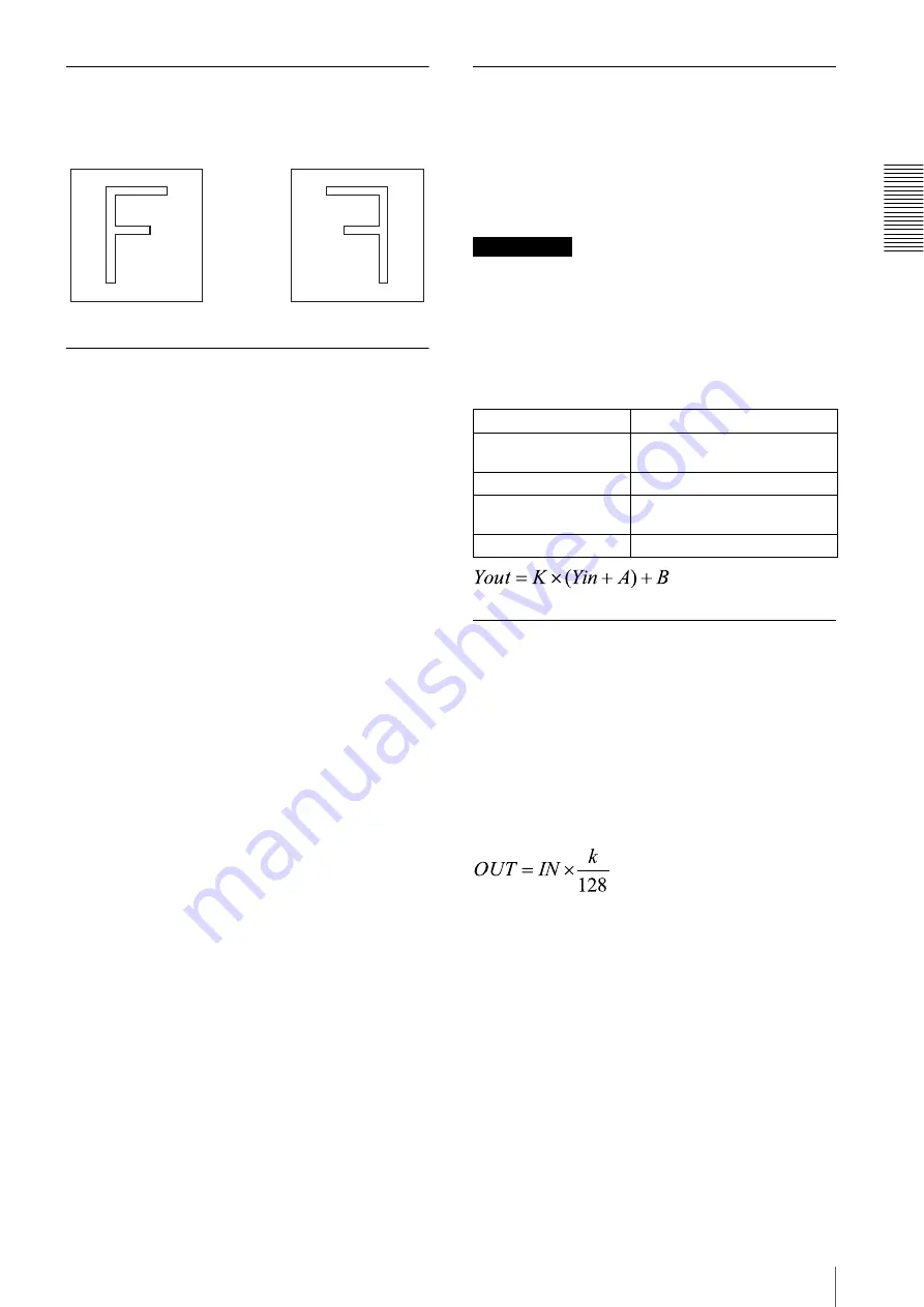
Flip-flop
[XCL-5005]
Configure this setting with FLIP-FLOP. It allows you to
output a mirror image.
6.3.
Digital clamp
[XCL-5005CR]
[XCL-5005]
Configure this setting with DCLAMP. You can add from
–255 to +255 steps to each of the images of the left and
right areas individually. Fine adjustment of either the left
or right level allows you to make the boundary in the
center of the window caused by the difference of the left
and right levels indistinguishable. This module is also
equipped with an automatic correction function
(automatic clamp control: AUTO-DCLAMP) that
detects the difference between the right and left levels
and then makes the boundary invisible. When the
automatic correction function is ON (AUTO-
DCLAMP=1), right and left digital clamp control
cannot be used. The automatic correction function is set
to ON at the time of shipment. The automatic correction
function provides two settings to allow you to fine-tune
the effectiveness.
6.3.1.
Clamp setting value
If you set the AUTO-DCLAMP parameter, you can
adjust the effectiveness of automatic clamp control.
Increasing the value makes automatic clamp control less
effective. Decreasing the value makes automatic clamp
control more effective, but the likelihood of level
variations in the left window increase. The optimal value
differs depending on the subject and exposure, so adjust
this setting according to the conditions.
6.3.2.
Correlation factor
Configure this setting with ADC-COEF. Increasing the
ADC-COEF value makes automatic clamp control more
effective. If a subject of variable density exists near the
left or right boundary of the window, the effectiveness of
automatic clamp control may be very great, so set a low
ADC-COEF value to stabilize the image.
6.4.
Digital gain
[XCL-5005]
Configure this setting with DGAIN, and the level with
DGAIN-STEP. Set the variable between ×1 to ×2
(+6 dB) and set the factor in 128 steps,
and Yout = Yin × factor.
Use this, for example, when the image is dark with
regards to AFE gain only.
Reference
The digital gain changes the whole display level, so
controlling just the digital gain will also alter the black
level at the same time. However, the black level can be
retained by subtracting the value in advance in the
previous step of the digital clamp, and then adding the
value in a subsequent step for the digital pedestal. At that
time, the output of the digital gain is as follows.
6.5.
Pixel gain
[XCL-5005CR]
Configure this setting with PIXEL-GAIN. You can set
the gain steps by color with RGAIN, GGAIN, and
BGAIN.
6.5.1.
Definition equation
You can set the gain individually for each of R, G, and B
pixels of the Bayer array. If the factor is k step, the
relation of the output level OUT to the input level IN is
expressed by the following equation.
The setting range of the factor is k = 0 to 2047
(Approximately 16 times, +24 dB). When k=128, IN is
multiplied by 1 (through). When k=0, the output is zero.
When the color temperature setting of the white balance
is manual, you can set the pixel gain individually for the
left side and right side of the center of the window.
FLIP-FLOP=0
FLIP-FLOP=1
Input value
Yin
Digital clamp subtraction
amount
A (–255 to +255)
Digital gain factor
K
Digital pedestal addition
amount
B
Output value
Yout


