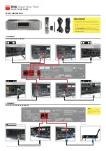
background image

WM-EX20

US Model

Canadian Model

AEP Model

UK Model

E Model

Australian Model

Tourist Model

SERVICE MANUAL

CASSETTE PLAYER

MICROFILM

SPECIFICATIONS

Model Name Using Similar Mechanism

NEW

Tape Transport Mechanism Type

MT-WMEX20-162

Manufactured under license from Dolby Laboratories
Licensing Corporation.
“DOLBY” and the double-D symbol 

a

 are trademarks

of Dolby Laboratories Licensing Corporation.

Tape section

Frequency response
(Dolby NR off)

Playback: 30 – 18,000 Hz

Output

Headphones (REMOTE 

2

 jack)

Load impedance 8 – 300 

General

Power requirements

1.5 V
One rechargeable battery or
one R6 (size AA) battery

Dimensions (w/h/d)

Approx. 78.7 

×

 108.6 

×

 18.7 mm

(3

1

/

8


×

 4

3

/

8


×


3

/

4  

inches), incl.

projecting parts and controls

Mass

Approx. 180 g (6.4 oz)
Approx. 240 g (8.5 oz) (incl.
  rechargeable battery and a cassette)

Supplied accessories

Battery case (1)
Stereo earphones with remote control (1)
Battery charger (1)

US, CND model : BC-7DC
AEP, FR model : BC-7DY
E, JE model : BC-7HT
UK model : BC-7S
AUS model : BC-7SG
KR model : BC-9HR

Rechargeable battery (1)

US, CND, AEP, UK, FR, AUS model :
NC-6WM, 1.2V, 600mAh, Ni-Cd
KR, E, JE model:
NH-14WM, 1.2V, 1400mAh, Ni-MH

Rechargeable battery carrying case (1)
Carrying pouch (1)
E, JE, model:

AC plug adaptor (1)

Design and specifications are subject to change without notice

• Abbreviation

CND : Canadian model
FR

: French model

AUS : Australian model
KR

: Korea model

JE

: Tourist model

Ver 1.0  1999. 08

Summary of Contents for Walkman WM-EX20

Page 1: ...R6 size AA battery Dimensions w h d Approx 78 7 108 6 18 7 mm 31 8 43 8 3 4 inches incl projecting parts and controls Mass Approx 180 g 6 4 oz Approx 240 g 8 5 oz incl rechargeable battery and a cassette Supplied accessories Battery case 1 Stereo earphones with remote control 1 Battery charger 1 US CND model BC 7DC AEP FR model BC 7DY E JE model BC 7HT UK model BC 7S AUS model BC 7SG KR model BC 9...

Page 2: ...Pin Function Discription 23 7 EXPLODED VIEWS 7 1 Cabinet Block Main Board 25 7 2 Mechanism Deck Block 26 8 ELECTRICAL PARTS LIST 27 SAFETY RELATED COMPONENT WARNING COMPONENTS IDENTIFIED BY MARK OR DOTTED LINEWITH MARK ON THE SCHEMATIC DIAGRAMS AND IN THE PARTS LIST ARE CRITICAL TO SAFE OPERATION REPLACE THESE COMPONENTS WITH SONY PARTS WHOSE PART NUMBERS APPEAR AS SHOWN IN THIS MANUAL OR IN SUPPL...

Page 3: ... 10 Hz at 1 3 Vp p to both PH IN T land TP37 and PH IN S land TP36 with jumper wire 4 Connect DC 1 3V from external regulated power supply to and terminals of the battery 2 PRE SET status The set must be in this state before the PLAY FF and REW modes can be entered 1 Make sure that the slider F R is in the center position and that the F R switch S702 is in the center position Make sure that the re...

Page 4: ...lywheel R insert flywheel N gear reel T side gear reel S side idler gear A T side idler gear A S side idler gear B gear Y gear NR FWD REV clutch assy F motor pulley gear FR reverse pulley insert flywheel R insert flywheel N gear reel T side idler gear A T side gear Y clutch assy F motor pulley gear FR gear reel S side reverse pulley insert flywheel R insert flywheel N idler gear A S side gear Y cl...

Page 5: ...N R Assy Magnetic Head HP701 Note Follow the disassembly procedure in the numerical order given The equipment can be removed using the following procedure 3 1 LID ASSY CASSETTE 3 2 CASE 1 Two screws M1 4 2 2 Lid assy cassette 3 2 Screw M1 4 2 2 4 Mechanism deck block 3 Two screws M1 4 2 2 4 Screw M1 4 1 6 5 2 Two screws M1 4 2 2 Case 1 Lid battery case ...

Page 6: ...ock assy 2 1 Release the two claws from the two holes in the direction allow Claw Hole Hole Claw 3 Screw M1 4 1 4 5 Screw M1 4 6 SUB board 2 Screw M1 4 qd MAIN board 1 Screw 4 Unsolder the 6 places qa Unsolder the motor 9 Unsolder the plunger 0 Unsolder the flexible board qs Claw 7 Screw M1 4 8 Switch leaf ...

Page 7: ... F KAI 3 5 BELT F KAI MOTOR M601 3 6 HOLDER ASSY 4 Screw M1 4 2 Shaft 6 Shaft 1 Two screws M1 4 1 4 3 Lock lever B 0 Remove the holder assy in the direction of the arrow 8 Remove soldering from Head flexible board 5 Lock lever S 9 Head flexible board 7 Bracket casette assy ...

Page 8: ... Claw Claw 2 Remove the pinch lever N assy in the direction of the arrow Note Be careful of the claw 1 Remove the pinch lever R assy in the direction of the arrow Note Be careful of the claw 1 Remove the magnetic head HP701 in the direction of the arrow ...

Page 9: ...EVIVE CONTROL Q303 HI UP CONTROL Q301 RIPPLE FILTER RIPPLE FILTER Q305 VOL MAX SWITCH Q307 DOLBY SWITCH Q312 REMOTE SWITCH Q708 VOL MIN SWITCH Q308 310 METAL SWITCH Q313 1 2 T REEL SENS PH701 MOTOR SW Q601 1 TAPE IN 2 ATS 12 10 41 39 40 42 43 44 46 S REEL SENS PH702 1 2 SPEED SWITCH Q602 INV Q705 706 MOTOR START SWITCH Q603 RV601 TAPE SPEED 21 30 29 28 S704 P SIG IN 1 50 P SIG IN 2 51 POWER CTL 23...

Page 10: ...01 PLUNGER V U W TV TW C TU L CH L CH FLEXIBLE BOARD R CH R CH HP701 PLAYBACK REV FWD EXCEPT FR MODEL FR MODEL DC IN 1 5V DRY BATTERY SIZE AA IEC DESIGNATION R6 1PCS 1 5V BATTERY CASE BATTERY CASE AEP UK FR MODEL DRY BATTERY SIZE AA IEC DESIGNATION R6 1PCS 1 5V US CND E JE KR AUS MODEL RECHAGEABLE BATTERY NH 14WM 1 2V 1400mA E JE KR MOSEL NH 6WM 1 2V 600mA US CND AEP UK FR AUS MODEL 1 2 A B C D E ...

Page 11: ... to ground under no signal detuned conditions no mark PLAY Voltages are taken with aVOM Input impedance 10 MΩ Voltage variations may be noted due to normal produc tion tolerances Waveforms are taken with a oscilloscope Voltage variations may be noted due to normal produc tion tolerances Circled numbers refer to waveforms Signal path E PB Abbreviation CND Canadian model AUS Australian model JE Tour...

Page 12: ... waveforms are dc with respect to ground under no signal detuned conditions no mark PLAY Voltages are taken with aVOM Input impedance 10 MΩ Voltage variations may be noted due to normal produc tion tolerances Waveforms are taken with a oscilloscope Voltage variations may be noted due to normal produc tion tolerances Circled numbers refer to waveforms Abbreviation CND Canadian model AUS Australian ...

Page 13: ... GM SUN BCH BLOCK SAME ACH 14 13 12 11 10 9 8 1 2 3 4 5 6 7 GND IREF VREF INB OUT B DC B DET B Vcc SW VEXT IN A OUT A DC A DET A IC601 LB1994M DECODER CTRL BLOCK POWER D DT PULSE BUFFER COMPARATOR BUFFER VI COMPARATOR SOFT CLIP CURRENT AMP P SIG PW SW 4 5 6 1 2 9 7 8 14 15 16 17 18 19 20 21 22 24 23 25 26 27 30 29 28 36 35 34 33 32 31 WS MC U IN 3 VCC V IN W IN CTRL1 CTRL2 DIR VS US U OUT NC V OUT...

Page 14: ... circuit control signal output L ON Not used Open Music with without detection AMS signal output H with L without Plunger control signal output H ON Rotational detection intermittent signal output H ON Not used Open Rotational detection intermittent signal output H ON Audio circuit and DDC control signal output L STOP H NORMAL Surround circuit control signal output L ON Ground Motor control signal...

Page 15: ... A MAIN BOARD COMPLETE EXCEPT FR 5 A 3061 997 A MAIN BOARD COMPLETE FR 6 3 038 624 01 LID BATTERY CASE 7 3 366 892 11 SCREW M1 4 1 4 8 X 3377 726 1 TERMINAL BOARD ASSY M 9 A 3052 056 A ORNAMENT OPEN BLOCK ASSY 10 3 038 627 01 SHEET CASE ADHESIVE 11 4 963 883 51 SCREW M1 4 PRECISION PAN 12 3 029 220 01 SPRING TENSION 13 3 365 630 41 SCREW M1 4 14 X 3377 717 1 BRACKET ASSY M 15 3 038 054 01 LEVER B ...

Page 16: ... KAI 68 3 007 433 01 SHEET N REFLECTION 69 3 029 283 01 GEAR IDLER A 70 3 029 765 01 SCREW M1 4 TOOTHED LOCK 71 3 029 268 11 FLYWHEEL R INSERT 72 3 029 883 01 RETAINER F1 MOTOR 73 3 029 273 01 GEAR FR 74 3 010 273 02 GEAR REEL 75 3 029 288 01 PULLEY REVERSE 76 3 010 954 01 SPRING BT COMPRESSION 77 3 010 274 02 TABLE REEL 78 3 029 289 01 WASHER 79 3 029 276 01 WASHER STOPPER R 80 3 007 428 01 WASHE...

Page 17: ...M CHIP 4 7uF 20 4V C302 1 113 600 11 TANTAL CHIP 2 2uF 20 6 3V C303 1 135 316 11 TANTAL CHIP 22uF 20 2 5V C304 1 115 156 11 CERAMIC CHIP 1uF 10V C305 1 164 360 11 CERAMIC CHIP 0 1uF 16V C307 1 135 149 21 TANTALUM CHIP 2 2uF 20 10V C308 1 164 505 11 CERAMIC CHIP 2 2uF 16V C309 1 125 837 91 CERAMIC CHIP 1uF 10 6 3V C310 1 165 112 11 CERAMIC CHIP 0 33uF 16V C311 1 165 128 11 CERAMIC CHIP 0 22uF 16V C...

Page 18: ... 5 1 16W R112 1 216 823 11 METAL CHIP 1 5K 5 1 16W R113 1 216 857 11 METAL CHIP 1M 5 1 16W R114 1 216 841 11 METAL CHIP 47K 5 1 16W R115 1 216 831 11 METAL CHIP 6 8K 5 1 16W R116 1 216 835 11 METAL CHIP 15K 5 1 16W R150 1 216 811 11 METAL CHIP 150 5 1 16W FR R201 1 216 845 11 METAL CHIP 100K 5 1 16W R202 1 216 831 11 METAL CHIP 6 8K 5 1 16W R203 1 216 831 11 METAL CHIP 6 8K 5 1 16W R204 1 216 835 ...

Page 19: ...05 11 SWITCH SLIDE VOLUME S701 1 762 516 11 SWITCH PUSH 1 KEY A B S702 1 771 475 21 SWITCH SLIDE F R VIBRATOR X701 1 767 289 11 VIBRATOR CERAMIC 4MHz 1 674 823 11 SUB BOARD SWITCH S703 1 771 053 21 SWITCH KEY BOARD OPERATION MISCELLANEOUS S704 1 762 553 11 SWITCH LEAF TAPE IN ATS M601 1 763 165 21 MOTOR CAPSTAN REEL MOTOR WITH PULLY HP701 1 500 623 11 HEAD MAGNETIC PLAYBACK PM701 1 454 674 32 SOLE...

Page 20: ... 30 WM EX20 Sony Corporation Personal Audio Company 99H1689 1 Printed in Japan 1999 8 Published by General Engineering Dept 9 927 157 11 ...

Reviews: