ICF-CD832
26
26
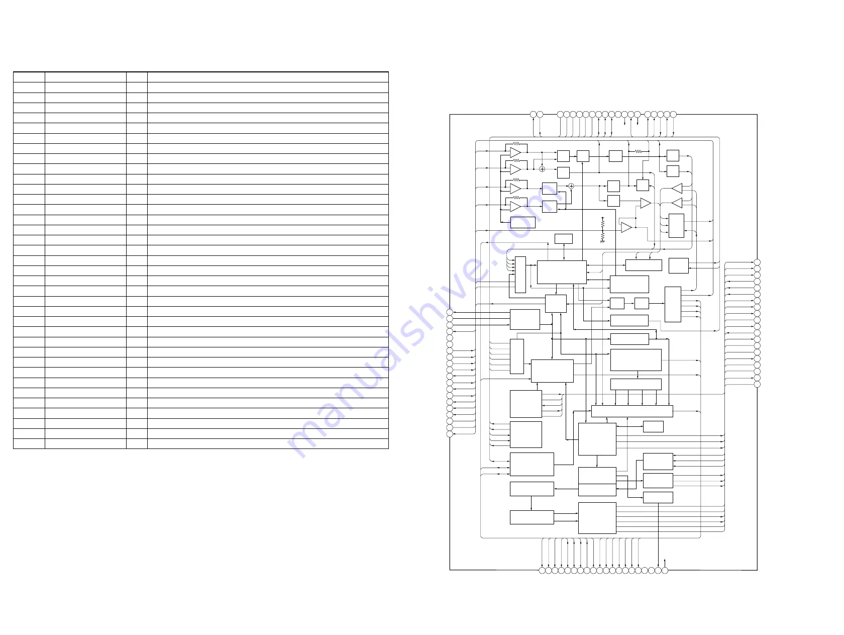
IC701 LC78646E-E (CD Board)
5-14. IC BLOCK DIAGRAMS
60
59
58
57
56
55
54
53
52
1
2
3
4
5
6
7
8
9
10
11
12
13
14
15
16
17
18
19
20
21 22 23 24 25 26 27 28 29 30 31 32 33 34 35 36 37 38
SLCO
SLCIST
EFMIN
RF
FDO
SPDO
SLDO
GPDAC
FDO
SPDO
SLDO
GPDAC
CONT4
CONT5
SBCK/CONT6
SBCK/FG
DEFECT
CONT4
CONT5
SBCK/CONT6
SBCK/FG
DEFECT
V/P
V/P
FSEQ
MONI1
MONI2
MONI3
MONI4
MONI5
V/P
FSEQ
MONI1
MONI2
MONI3
MONI4
MONI5
VSS
VDD(3.3V)
69 68 67 66
65 64 63 62 61
VSS
VDD5
DRF
RES
WRQ
DO
DI
CL
CE
79
78 77 76 75 74 73 72 71
LDS
80
LDD
FR
VVDD
PCKIST
VVSS
PDO2
PDO1
CONT1
CONT2
70
CONT3
WRQ
DO
DI
CL
CE
FR
VVDD
PCKIST
VVSS
SBCK/FG
PDO2
PDO1
CONT1-3
SBCK/CONT6
CONT4,5
DRF
WRQ
DO
DI
CL
CE
LDS
LDD
LDS
LDD
FR
VVDD
PCKIST
VVSS
PDO2
PDO1
CONT1
CONT2
CONT3
RFVDD
RFVSS
FIN1
FIN2
TIN1
TIN2
VREF
FIN1
FIN2
TIN1
TIN2
REFI
REFI
DEFECT
FE
TEC
TE
RFMON
JITTC
ADAVDD
ADAVSS
TDO
SLCO
SLCIST
EFMIN
RF
FIN1
FIN2
TIN1
TIN2
VREF
REFI
FE
TEC
TE
RFMON
JITTC
JITTC
ADAVDD
ADAVSS
ADAVDD
ADAVSS
TDO
DATA
DATACK
LRSY
ASDFIN
ASDACK
ASLRCK
DATA
DATACK
LRSY
RVDD
RVSS
RCHO
LCHO
LVSS
LVDD
ASDFIN
ASDACK
ASLRCK
16MOUT
EFLG
C2F
FSX/16MIN
EFLG
C2F
FSX/16MIN
XVSS
XIN
XOUT
XVDD
16MOUT
XVSS
XIN
XOUT
XVDD
RVDD
RCHO
RVSS
LVSS
LCHO
LVDD
DATA
DATACK
LRSY
ASDFIN
ASDACK
ASLRCK
16MOUT
EFLG
C2F
FSX/16MIN
XVSS
XIN
XOUT
XVDD
RVDD
RCHO
RVSS
LVSS
LCHO
LVDD
39 40
DOUT
TEST
51
50
49
48
47
46
45
44
43
42
41
+
–
MIX
PH
BH
MONI
CONT
EQ
+
–
+
–
+
–
+
–
+
–
+
–
LPF
TBAL
TBAL
RAM
TDO
TRACK JUMP
SW
D/A
APC
SUBCODE DECODE CRC
GENERAL PURPOSE
PORTS
8FS
DIGITAL FILTER
1BIT DAC
LPF
ERROR
CORRECTION
AUDIO CD
MONITOR SIGNAL SELECTOR
EXTERNAL
AUDIO IN
AUTO ADJUST
FRAME SYNC
DETECT,PROTECT,INSERT,
EFM DECODE
A/D
CLOCK
GENERATOR
COMMAND
INTERFACE
SERVO PROCESSOR
LEVEL SET
+
–
S/H
SW
DRF
DRF
ATTENUATION
DEEMPHASIS
INTERPOLATION
MUTE
RUPTURE DEFECT
SLICE LEVEL
CONTROL
CLV,CAV
CONTROL
SERIAL
OUT
AUDIO OUT
RAM
JITTER
DETECT
PLL
VCEC
FE
TE
TEC
RF
RFMON
VREF
SPDO
SLDO
GPDAC
FSEQ
MONI1-5
FDO
LPF
LPF
AGC
5-13. IC PIN DESCRIPTION
• IC401 uPD789477GC-A28-8BT (SYSTEM CONTROL)
Pin No.
Pin Name
I/O
Pin Description
1 to 29
NC
—
Note used (Open)
30 to 37
SEG7 to SEG0
O
LED segment driver signal output
38
AVDD
—
Power supply pin (+3.3 V)
39
FSEQ
I
CD frame sync input
40
CD OPEN
I
CD open detection signal input
41
VERSION
I
Distination select signal input
42, 43
KEY1, KEY0
I
Key data input
44 to 46
SW2 to SW0
I
Switch data input
47
AVSS
—
Ground
48
NC
—
Not used (Open)
49
AC IN
I
AC power failure detection signal input
50
WRQ
I
CD write request data input
51
50/60HZ
I
LED display sync signal input
52
BUZZER
O
Beep sound output
53
CD DATA IN
I
CD serial data input
54
DATA
I/O
CD serial data input/ouput
55
CLK
O
CD serial clock signal output
56
LAT
O
CD latch signal output
57
DRF
I
CD DRF signal input
58
XRST
O
CD reset signal output
59
A MUT
O
Audio mute control signal output
60
POWER ON
O
Power AMP standby control signal output
61
BRIGHTNESS
O
LED brightness control signal output
62 to 68
SEG14 to SEG8
O
LED segment driver signal output
69
IC
—
Connecting to Ground
70
XT1
—
Sub system clock (32.768 kHz)
71
XT2
—
Sub system clock (32.768 kHz)
72
VDD0
—
Power supply pin (+3.3 V)
73
VSS0
—
Ground
74
X1
—
Main system clock (4.19 MHz)
75
X2
—
Main system clock (4.19 MHz)
76
RESET
—
System reset signal input
77
RADIO ON
O
Radio power supply control signal output
78
CD ON
O
CD power supply control signal output
79
CD/RADIO
O
CD/RADIO indicator drive signal output
80
NAP LED
O
NAP indicator drive signal output


