background image

51

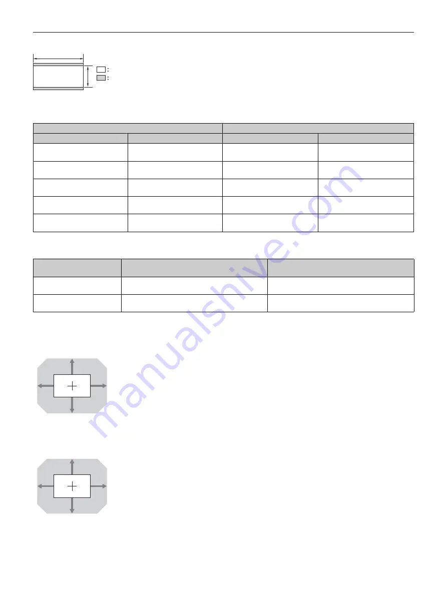
When projecting in 2.35:1 format

Projection distance

Unit: m (inches)

Projection distance formula

D: Projected image size (Diagonal)

Unit: m (inches)

Lens shift range

VPLL-Z7008

VPLL-Z7013

Projection image size

Projection distance L

Diagonal

Width × Height

VPLL-Z7008

VPLL-Z7013

80" (2.03 m)

1.87 × 0.80 

(74 × 31)

1.49 – 1.89

(59 – 74)

2.33 – 5.10

(92 – 200)

100" (2.54 m)

2.34 × 0.99 

(92 × 39)

1.88 – 2.39

(74 – 94)

2.93 – 6.39

(116 – 251)

120" (3.05 m)

2.80 × 1.19 

(110 × 47)

2.26 – 2.88

(89 – 113)

3.53 – 7.69

(139 – 302)

150" (3.81 m)

3.51 × 1.49 

(138 × 59)

2.85 – 3.61

(112 – 142)

4.43 – 9.63

(175 – 379)

200" (5.08 m)

4.67 × 1.99 

(184 × 78)

3.82 – 4.84

(151 – 190)

5.93 – 12.86

(234 – 506)

Lens

Projection distance L 

(minimal length)

Projection distance L 

(maximal length)

VPLL-Z7008

L = 0.019441 × D – 0.0733

(L = 0.765407 × D – 2.8875)

L = 0.024567 × D – 0.0664

(L = 0.967219 × D – 2.6152)

VPLL-Z7013

L = 0.030024 × D – 0.0800

(L = 1.182064 × D – 3.1491)

L = 0.064723 × D – 0.0756

(L = 2.548138 × D – 2.9775)

2.35

1

Video display area

Projection area

62%

62%

18%

18%

VS + = VS – = 62 – 3.444 × (HS + or HS –) [%]
HS + = HS – = 18 – 0.290 × (VS + or VS –) [%]

100%

100%

31%

31%

VS + = VS – = 100 – 3.226 × (HS + or HS –) [%]
HS + = HS – = 31 – 0.310 × (VS + or VS –) [%]

Summary of Contents for VPL-GTZ270

Page 1: ...rojector Operating Instructions Before operating the unit please read this manual and supplied Safety Regulations thoroughly and retain it for future reference VPL GTZ270 4 584 926 13 1 2016 Sony Corporation ...

Page 2: ...Operation through the Menus 18 Picture Menu 20 Advanced Picture Menu 24 Screen Menu 25 Setup Menu 27 Function Menu 29 Items Locked by Settings Lock 31 Installation Menu 32 Information Menu 35 About the Preset Memory 35 Using Network Features Displaying the Control Window of the Unit with a Web Browser 36 Operating the Control Window 37 Switching the Page 37 Setting the Access Limitation 37 Confirm...

Page 3: ... the signals to control the projector When connecting to the IR IN connector the remote control detector does not work with the remote control IR OUT Outputs the control signals received at the projector to the connected devices When operating the projector with the remote control the connected devices can also be operated i TRIGGER 1 TRIGGER 2 connector page 32 j Connector light switch Turns on o...

Page 4: ...ge 8 Others s Lens not supplied page 43 t Ventilation holes intake If you look through the projection lens while the unit is projecting the light may damage your eyes Take special caution when using the unit around children Rear Bottom a Remote control detector page 8 b Ventilation holes exhaust c Feet adjustable page 10 When using the unit in the upside down position you can remove the feet and a...

Page 5: ...e Press again to restore the image POSITION button Stores and recalls the lens settings page 16 MOTIONFLOW button Reproduces fast moving images smoothly page 21 CONTRAST ENHANCER button Corrects the image automatically to optimize the contrast according to a scene page 21 REALITY CREATION button Adjusts the detail and noise processing of images page 20 g ID MODE switch Sets the ID mode of the remo...

Page 6: ...mote Control Caution about handling the remote control Handle the remote control with care Do not drop or step on it or spill liquid of any kind onto it Do not place the remote control in a location near a heat source a place subject to direct sunlight or a damp room Connecting the AC Power Cord 1 Plug the AC power cord into the AC IN socket then attach the plug holder to the AC power cord 2 Slide...

Page 7: ... stripes pattern may rarely appear on the screen depending on the distance between the screen and the unit or the zooming magnifications This is not a malfunction of the unit Selecting the Menu Language The factory setting for the language for displaying menus messages etc is English To change the on screen language proceed as follows 1 After connecting the AC power cord to the unit plug the AC po...

Page 8: ...ocus Lens Zoom and Lens Shift Depending on the installation location of the unit you may not be able to control it with the remote control In this case point the remote control at the remote control detector of the unit or the screen 1 Adjust the focus Press the FOCUS button to display the Lens Focus adjustment window test pattern Then adjust the focus of the picture by pressing the M m buttons Ti...

Page 9: ...g the picture position do not touch the lens unit otherwise your fingers may be pinched by the moving parts To adjust the horizontal position Press The picture projected on the screen moves right or left from the center of the lens Top view To adjust the vertical position Press M m The picture projected on the screen moves up or down from the center of the lens Side view The range to move the pict...

Page 10: ...stable to keep the unit level If the unit is tilted up or down the projected image may be trapezoidal Be careful not to catch your finger when turning the feet adjustable Lens adjustment window test pattern Notes Projected Picture Feet adjustable Turn to adjust 1 78 1 16 9 2 35 1 1 85 1 1 33 1 4 3 The dashed lines show the screen sizes of each aspect ratio ...

Page 11: ...Use a High Speed or Premium High Speed HDMI cable With a standard HDMI cable images of 1080p DeepColor 3D video and 4K video may not be displayed properly When you want to display a picture in a more detailed HDMI format use the Premium High Speed type When connecting an HDMI cable to the unit make sure the V mark on the upper part of the HDMI input of the unit and the v mark on the connector of t...

Page 12: ...isplayPort input 1 and DisplayPort input 2 of the unit respectively If no picture is projected with the workstation connected to the unit with DisplayPort cables check the settings of the workstation or graphic boards Connecting to a workstation V Split display connection Note Right side of the unit DisplayPort output DisplayPort cables not supplied Video signal flow Workstation ...

Page 13: ...t cable is not correct check the settings of the connected equipment If you set your computer such as a notebook type to output the signal to both computer s display and this equipment the picture of the equipment may not appear properly Set your computer to output the signal to only the external monitor For details refer to the computer s operating instructions supplied with your computer For set...

Page 14: ...ctor starts shutdown and turns off 2 Unplug the AC power cord from the wall outlet Never disconnect the AC power cord while the unit is turned on Projecting High Resolution Images V Split display Signals transferred after an image is split at 4096 2160 or 3840 2160 resolution are projected 1 Connect DisplayPort output 1 and DisplayPort output 2 of the workstation to DisplayPort input 1 and Display...

Page 15: ...ation range page 15 There are differences in perception of 3D video images among individuals When the temperature of the usage environment is low the 3D effect may be diminished Adjusting Setting the 3D functions You can adjust set the 3D functions with the 3D Settings of the Function menu For details see 3D Settings page 29 1 Turn on the 3D glasses and register them on the unit For details on how...

Page 16: ... 2 35 1 screen After you have selected and confirmed the lens position the lens starts to move Do not touch or place anything near the lens otherwise it may cause injury or a malfunction If you press any button on the remote control or the unit while the lens is moving the lens stops In this case select the lens position again or adjust the lens manually The Picture Position function is not guaran...

Page 17: ...pect setting Select the aspect mode taking into account that changing the aspect ratio of the original picture will provide a different look from that of the original image Note that if the unit is used for profit or for public viewing modifying the original picture by switching the aspect may constitute an infringement of the rights of authors or producers which are legally protected Original ima...

Page 18: ...llowed by an arrow B the next menu window with setting items appears 1 Press MENU The menu window appears 2 Press M m to select a menu item and press or ENTER The items that can be set or adjusted with the selected menu appear The item presently selected is shown in white 3 Press M m to select an item you want to set or adjust and press or ENTER The setting items are displayed in a pop up menu in ...

Page 19: ...djusted Select Reset from the Picture menu When the screen display appears select Yes using and press ENTER All of the following settings are reset to its factory preset value Reality Creation Cinema Black Pro Motionflow Contrast Brightness Color Hue Color Temp Sharpness and Expert Setting on the Picture menu To reset the items that have been adjusted Select an item in the menu screen and display ...

Page 20: ...y suited for watching movies in a bright environment Bright TV Picture quality suited for watching TV programs sports concerts and other video images in a bright environment User 1 User 2 User 3 You can adjust the picture quality to suit your taste and save the setting The factory default setting is the same as Reference Tip Any adjustments to picture quality settings are saved for each input Rese...

Page 21: ...ts in a distorted picture When selecting Impulse the picture becomes dark Also it may flicker Depending on the picture content you may not see the effect visually even if you have changed the settings Only Off or Impulse is available when a signal with a resolution of 4096 2160 is input Contrast CONTRAST Adjusts the contrast Higher values increase the sharpness in images while lower values decreas...

Page 22: ...ff The smooth gradation function is not applied Tip This item is not available for 3D signals Film Mode According to the film source you have selected make a setting for playback Auto Suitable for reproducing the original picture movement Normally set this to Auto Off Plays back the picture in progressive format without detecting video signals automatically Tip This item is compatible with a 1080i...

Page 23: ...BT 709 color space The color space is equivalent to sRGB BT 2020 An approximated ITU R BT 2020 color space which has a wider range of color reproduction than BT 709 Use this setting when playing back HDR content DCI A color space based on the DCI specification page 42 Adobe RGB An approximated Adobe RGB color space which has a wider range of color reproduction than sRGB and suited for displaying a...

Page 24: ...wer has been on for more than 30 minutes It takes a few minutes for Pre Check or Adjust to complete When Pre Check or Adjust starts the screen position may shift as the lens returns to its factory default position After completion the screen returns to its previous position automatically If the environment such as the brightness of the room changes while performing Pre Check or Adjust measurement ...

Page 25: ...arts to move Do not touch the lens and the area around the lens otherwise it may cause injury or a malfunction If you press any button on the remote control or the unit while the lens is moving the lens stops In this case select the lens position again or adjust the lens manually When you use a 2 35 1 or a 16 9 subtended angle with the Picture Position function make sure that the installation posi...

Page 26: ...ip Depending on the aspect ratio setting right left blanking may not be available Image Shift On You can adjust the image position H The image moves to the right as the value increases and moves to the left as decreases V The image moves up as the value increases and moves down as decreases Off You can turn off the image shift function Tip When displaying one image with two projectors installed si...

Page 27: ... the product reliability of its components and the fan noise may become louder Periodic LD Calibration Performs the calibration automatically after a certain period of use At that time the calibration starts when the 1 button of the unit or the 1 button of the remote controller is pressed and after the calibration finishes the power turns off On Performs the calibration automatically Off Does not ...

Page 28: ...d Set Network Management to Off for normal use If you set to On the power consumption increases Power Saving Sets the Power Saving mode Standby If no signal is input for 10 minutes power is turned off automatically and the projector goes into standby mode Off Disables the Power Saving function All Reset All settings by the main unit and adjusted data by the connected devices are initialized to the...

Page 29: ... among individuals Side by Side Select this to display 3D images as two similar images side by side Over Under Select this to display 3D images as two similar images one above the other Tips 2D 3D Display Sel cannot be set to 3D for some video sources For available 3D signals see Compatible 3D Signals page 45 The simulated 3D feature may have limited effect depending on the projection image size 1...

Page 30: ...rmat Set Enhanced Format only when the corresponding devices are used It may take time to display a picture after switching the video signal formats Stream Format Selects the signal format for DisplayPort Single Select this format for the SST Single Stream Transmission compatible signal of DisplayPort Dual Select this format for the MST Multi Stream Transmission compatible signal Test Pattern Disp...

Page 31: ...amma Correction Color Correction Clear White x v Color HDR Color Space Input Lag Reduction Advanced Picture menu Auto Calibration Setup menu Periodic LD Calibration Setup menu Status Language Menu Position Constant Brightness High Altitude Mode Remote Start Network Management Power Saving Function menu Dynamic Range Test Pattern Installation menu Image Flip Lens Control Trigger Select IR Receiver ...

Page 32: ...wer Outputs 12 V signals from the TRIGGER 1 TRIGGER 2 connectors when the unit is on The TRIGGER 1 TRIGGER 2 connectors do not output any signals when the unit is in standby 2 35 1 Zoom Works with the Aspect setting s 2 35 1 Zoom page 25 and outputs a 12 V signal from the TRIGGER 1 or TRIGGER 2 connector 3D Outputs a 12 V signal from the TRIGGER 1 or TRIGGER 2 connector when the 3D signal is input...

Page 33: ...ns for the vertical position V Position then press ENTER Set the amount to adjust with the buttons for the horizontal direction H and with the M m buttons for the vertical direction V You can select the position to adjust again by pressing ENTER Reset Returns to the factory settings Off The optimized data has been preset Depending on the adjustments made above colors may become uneven or the resol...

Page 34: ...cense Unique Device ID Displays the ID number of the unit Tip For details on features activated by Activate Licenses refer to the following web site https www ecspert sony biz Supported Web browsers are as follows Windows OS Internet Explorer 10 11 Microsoft Edge Windows 10 Google Chrome Mac OS Safari Setting items Description Note ...

Page 35: ...rmation menu Depending on the computer input signal parts of projection image may be hidden or displayed incorrectly Items Description Model Name Displays the model name Serial No Displays the serial number Signal type Displays the resolution of the video which you are watching When input signals with 3D information are input the type of input signals and the 3D format are displayed When the input...

Page 36: ...he menu displays only English If the browser of your computer is set to Use a proxy server when you have access to the unit from your computer click the check mark to set accessing without using a proxy server AMX DDDP is not compatible with IPv6 These network functions are available when the unit is turned on Displaying the Control Window of the Unit with a Web Browser 1 Connect the LAN cable 2 S...

Page 37: ...sword The name of the administrator is preset to root The password can be changed in the Password page in the Setup page When you change the password input a new password after deleting the password that was set The password of the administrator and user should be 8 to 16 characters that includes both alphabet and numeric characters Alphabet is case sensitive The default password Projector cannot ...

Page 38: ...isplayed in 3D Watch the 3D video images using the 3D glasses and set 2D 3D Display Sel to 3D 15 29 Bright or dark area of the video appears too bright or too dark This symptom may occur when a signal level other than those of HDMI standard is input Switch the output level of the connected equipment or switch the Dynamic Range on the Function menu of the unit 30 The picture is too dark Adjust Cont...

Page 39: ...ications of the connected AV selector AV amplifier external equipment If the 3D signal is not input confirm the specifications and or settings of the AV selector AV amplifier external equipment When the viewing position is too far from the unit the 3D glasses may not be able to display the images properly 15 The projection image size is not appropriate Set the zooming magnification to low or watch...

Page 40: ... power after a while If the symptom persists consult qualified Sony personnel Six times The unit detects a drop impact If there is abnormality on the unit consult with qualified Sony personnel If there are no abnormalities on the unit disconnect the AC power cord and check that the ON STANDBY indicator turns off then connect the AC power cord and turn the unit on Eight times The lens is not secure...

Page 41: ... When using the unit at high altitude set High Altitude Mode to On When temperature inside the unit remains high High Altitude Mode is switched to On in 1 minute then the fan speed increases 27 Power Saving Mode is set Projector will automatically enter Standby Mode in 1 minute Power Saving is set to Standby If no signal is input the power turns off after 1 minute and the projector goes into stand...

Page 42: ...one of sRGB that is used with the current television system About the Simulated 3D Feature Use the simulated 3D function taking into account that the picture will provide a different look from the original images because this function converts the video images Note that if the unit is used for profit or for public viewing displaying 2D video images as 3D video images by converting to the simulated...

Page 43: ...TRIGGER connectors 2 mini jack DC 12 V Max 100 mA Sync connectors IN 1 OUT 1 Outside dimensions w h d 550 mm 228 mm 750 mm 21 21 32 inches 8 31 32 inches 29 17 32 inches Mass Approx 40 0 kg 88 lb 1 7 oz excluding the lens Power requirements AC 220 V to 240 V 6 A 50 60 Hz for Europe and China AC 100 V to 240 V 12 A to 6 A 50 60 Hz for countries other than Europe and China Power consumption 1 2 kw m...

Page 44: ...ing 720 60p 1280 720 60p 90 000 60 000 z 19 720 50p Frame packing 720 50p 1280 720 50p 75 000 50 000 z 20 1080 24p Frame packing 1080 24p 1920 1080 24p 53 946 23 976 z 26 640 480 VGA 31 469 59 940 H Neg V Neg z 32 800 600 SVGA 37 879 60 317 H Pos V Pos z 37 1024 768 XGA 48 363 60 004 H Neg V Neg z 45 1280 960 QVGA 60 000 60 000 H Pos V Pos z 47 1280 1024 SXGA 63 974 60 013 H Pos V Pos z 55 1280 76...

Page 45: ...t be selected are not displayed in the menu 94 3840 2160 25p 3840 2160 25p 3840 2160 56 250 25 000 z 95 3840 2160 30p 3840 2160 30p 3840 2160 67 433 29 970 z 3 z 96 4096 2160 24p 4096 2160 24p 4096 2160 54 000 24 000 z 3 z Preset memory no Preset signal resolution fH kHz fV Hz Sync DisplayPort HDMI Input Signals and Adjustment Setting Items Item Preset memory number 5 to 8 10 to 14 18 to 20 71 72 ...

Page 46: ...oom z z z z 2 35 1 Zoom z z z z Normal z z z z z z Stretch z Acceptable signals 1920 1080 1280 720 3D format Side by Side Over Under Frame packing Simulated 3D Preset memory number page 44 7 8 10 to 14 10 to 14 18 to 20 71 72 7 8 10 to 14 1 85 1 Zoom z z z z 2 35 1 Zoom z z z z Normal z z z z Stretch Storage Conditions of Adjustment Setting Items Item Storage conditions Calib Preset For each input...

Page 47: ...d Calib Preset NR MPEG NR Smooth Gradation Film Mode Gamma Correction Color Correction Clear White x v Color HDR Color Space BT 709 Custom Red For each Color Space Green Blue Cyan Red Magenta Green Input Lag Reduction For each input connector and Calib Preset Item Storage conditions Aspect For each Picture Position Blanking Item Storage conditions ...

Page 48: ...cross at right angles is aligned with the center of the projected image and full width or full height of the projected image is regarded as 100 VS Vertical lens shift range up VS Vertical lens shift range down HS Horizontal lens shift range right HS Horizontal lens shift range left Projection distance L Projected image Front of the lens Lens shift range Projected image Center of the lens 50 50 Cen...

Page 49: ... 2 81 6 14 111 241 120 3 05 m 2 70 1 42 106 56 2 17 2 76 86 108 3 39 7 38 134 290 150 3 81 m 3 37 1 78 133 70 2 74 3 47 108 136 4 25 9 25 168 364 200 5 08 m 4 49 2 37 177 93 3 67 4 65 145 183 5 70 12 36 225 486 Lens Projection distance L minimal length Projection distance L maximal length VPLL Z7008 L 0 018689 D 0 0733 L 0 735786 D 2 8875 L 0 023617 D 0 0664 L 0 929788 D 2 6152 VPLL Z7013 L 0 0288...

Page 50: ...1 90 2 41 75 95 2 96 6 46 117 254 120 3 05 m 2 66 1 49 105 59 2 29 2 91 90 114 3 56 7 77 141 305 150 3 81 m 3 32 1 87 131 74 2 88 3 65 114 143 4 47 9 73 176 383 200 5 08 m 4 43 2 49 174 98 3 86 4 89 152 192 5 99 13 00 236 511 Lens Projection distance L minimal length Projection distance L maximal length VPLL Z7008 L 0 019643 D 0 0733 L 0 773332 D 2 8875 L 0 024822 D 0 0664 L 0 977234 D 2 6152 VPLL...

Page 51: ... 80 1 19 110 47 2 26 2 88 89 113 3 53 7 69 139 302 150 3 81 m 3 51 1 49 138 59 2 85 3 61 112 142 4 43 9 63 175 379 200 5 08 m 4 67 1 99 184 78 3 82 4 84 151 190 5 93 12 86 234 506 Lens Projection distance L minimal length Projection distance L maximal length VPLL Z7008 L 0 019441 D 0 0733 L 0 765407 D 2 8875 L 0 024567 D 0 0664 L 0 967219 D 2 6152 VPLL Z7013 L 0 030024 D 0 0800 L 1 182064 D 3 1491...

Page 52: ...550 21 21 32 65 2 9 16 L The distance between the front of the lens center and the front of the cabinet VPLL Z7008 159 0 mm 6 1 4 inches Tele to 185 2 mm 7 9 32 inches Wide VPLL Z7013 130 2 mm 5 1 8 inches L 131 5 5 32 VPLL Z7013 134 5 9 32 VPLL Z7008 197 7 3 4 692 7 27 9 32 28 6 1 1 8 492 7 19 13 32 28 6 1 1 8 ...

Page 53: ...tting items 45 Intake Air Temp 35 IR Receiver 32 L LAN connector 36 Language 27 Laser Light Setting 21 Lens adjustment window 10 Lens Control 32 License Management 34 Light Timer 35 Location of controls Front 3 Rear Bottom 4 M Menu Advanced Picture 24 Function 29 Information 35 Installation 32 Operation 18 Picture 20 Screen 25 Setup 27 Menu Position 27 Messages Caution 41 Warning 41 Motionflow 21 ...

Page 54: ...Sony Corporation ...

Reviews: