background image

Adjusting the Printer Picture Quality

57

Saving and Loading Adjustment 
Values

Once picture quality adjustment is complete, you can 
follow the procedure below to save the adjustment 
values so that they can be loaded and used later.

To save adjustment values

Once adjustment is complete, save the adjustment 
values as follows:

1

In the COLOR ADJUST COLOR [>>] screen or 
B/W [>>] screen of the printer, press 

B

 on the 

control button.

2

Press 

V

 on the control button repeatedly until the 

SAVE SETTING screen appears.

3

Press 

b

 or 

B

 on the control button to select the 

memory-cell number (1, 2, or 3).

4

Press the EXEC button.
The adjustment values are saved in the memory-cell 
number selected in step 

3

.

To load adjustment values

You can load adjustment values saved in memory as 
follows.

1

In the COLOR ADJUST COLOR [>>] screen or 
B/W [>>] screen of the printer, press 

B

 on the 

control button.

2

Press 

V

 on the control button repeatedly until the 

LOAD SETTING screen appears.

3

Press 

b

 or 

B

 on the control button to select the 

memory-cell number (1, 2, or 3).

4

Press the EXEC button.
The adjustment values saved in the memory-cell 
number selected in step 

3

 are loaded.

To exit COLOR ADJUST

Once operations such as adjustments, saving adjustment 
values, and loading adjustment values are complete, 
press the MENU button. The READY screen reappears.

Note

If the READY screen is not retrieved, CHECK 
PRINTER appears on the LCD of the camera when 
printing is to be performed, and printing cannot be 
performed. When you have finished making 
adjustments, be sure to press the MENU button to 
retrieve the READY screen.

Explanation of Picture Quality 
Adjustment Parameters

Picture quality variations when the R, G, 
and B parameters are changed

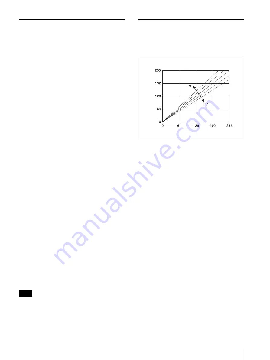
CYN-RED adjustment (R parameter)

You can adjust the cyan and red color components. The 
default is 0.
Pressing 

B

 on the control button of the printer changes 

the value in the plus direction to 1, 2 … 7, making the 
red component value in the picture increase in the linear 
direction that the brightness increases as shown in figure 
1. This adds more red as if a red light has been cast. 
However, the maximum effective brightness value is 
255. When the value becomes larger than 255, saturation 
occurs. When this occurs, the saturated white area 
remains white even if the value is increased further in the 
plus direction.
Pressing 

b

 on the control button changes the value in the 

minus direction to –1, –2 … –7, making the red 
component value in the picture decrease in the linear 
direction that the brightness decreases as shown in the 
figure. Decreasing the brightness makes the red color 
darker and reduces the redness. The complementary 
color cyan (light blue) is added. In this case, the white 
area becomes bluish.

Light

Variation

Level

Dark

Light

Subject

Figure 1

Summary of Contents for UPX-C100

Page 1: ...2 886 280 13 1 Digital Printing System 2006 Sony Corporation UPX C100 Operating Instructions ______________________________________ GB ...

Page 2: ...equipment and receiver Connect the equipment into an outlet on a circuit different from that to which the receiver is connected Consult the dealer or experienced radio TV technician for help You are cautioned that any changes or modifications not expressly approved in this manual could void your authority to operate this equipment All interface cables used to connect peripherals must be shielded i...

Page 3: ...uments For the customers in the USA and Canada RECYCLING NICKEL METAL HYDRIDE BATTERIES Nickel Metal Hydride batteries are recyclable You can help preserve our environment by returning your used rechargeable batteries to the collection and recycling location nearest you For more information regarding recycling of rechargeable batteries call toll free 1 800 822 8837 or visit http www rbrc org Cauti...

Page 4: ...e Resolution IMAGE RESOLUTION 42 Setting the Auto Erase Mode AUTO ERASE 43 Adjusting the White Balance WHITE BALANCE 44 Viewing Information on Captured Images PICTURE INFO 44 Setting the Frame FRAME 45 Setting the Print Size PRINT SIZE LIST 50 Selecting the Units for Size Display SIZE UNIT 51 Setting the Date and Time DATE TIME 52 Selecting the Language Display LANGUAGE 53 Setting Camera Sounds CA...

Page 5: ...supported UPC X46 series UPC X45 series and UPC X34 series The optional UPA DX100TR paper tray and 10UPC X45 Series Self laminating Color Printing Pack however may not be available in some countries and regions For detailed information contact your nearest Sony dealer System Configuration By connecting the camera to a printer by USB cable you can send images to the printer for printing Note Camera...

Page 6: ...1 7 8 1 1 2 12 45 45 mm 1 13 16 1 13 16 11 45 35 mm 1 13 16 1 7 16 13 43 33 mm 1 3 4 1 5 16 14 38 32 mm 1 1 2 1 5 16 15 34 28 mm 1 3 8 1 1 8 16 23 23 mm 29 32 29 32 8 54 54 mm 2 1 4 2 1 4 18 60 40 mm 2 3 8 1 5 8 D2 2 pictures 2 prints each 19 47 37 mm 1 7 8 1 1 2 D3 3 pictures 2 prints each 20 45 35 mm 1 13 16 1 7 16 D2 2 pictures 4 prints each 17 80 60 mm 3 1 4 2 3 8 D2 2 pictures 1 print each 22...

Page 7: ...System Overview 7 Guide print These guides are useful when adjusting the image quality of the printer Guide Print DLGm Guide Print RGB ...

Page 8: ...0 50 mm 2 7 8 2 7 60 40 mm 2 3 8 1 5 8 9 50 48 5 mm 2 1 15 16 8 54 54 mm 2 1 4 2 1 4 12 45 45 mm 1 13 16 1 13 16 15 34 28 mm 1 3 8 1 1 8 16 23 23 mm 29 32 29 32 18 60 40 mm 2 3 8 1 5 8 D2 2 pictures 2 prints each 19 47 37 mm 1 7 8 1 1 2 D3 3 pictures 2 prints each 20 45 35 mm 1 13 16 1 7 16 D2 2 pictures 3 prints each 17 80 60 mm 3 1 4 2 3 8 D2 2 pictures 1 print each 21 Special 1 80 60 mm 47 37 m...

Page 9: ...7 8 1 1 2 12 45 45 mm 1 13 16 1 13 16 8 54 54 mm 2 1 4 2 1 4 9 50 48 5 mm 2 1 15 16 11 45 35 mm 1 13 16 1 7 16 13 43 33 mm 1 3 4 1 5 16 14 38 32 mm 1 1 2 1 5 16 3 95 70 mm 3 3 4 2 7 8 4 80 60 mm 3 1 4 2 3 8 5 70 53 mm 2 7 8 2 1 8 6 70 50 mm 2 7 8 2 20 45 35 mm 1 13 16 1 7 16 D2 2 pictures 2 prints each 21 Special 1 70 53 mm 47 37 mm 2 7 8 2 1 8 1 7 8 1 1 2 22 Special 2 47 37 mm 43 33 mm 1 7 8 1 1 ...

Page 10: ...lfway activates the autofocus function and pressing it all the way releases the shutter The captured image is compressed and saved in JPEG format This button is active only when the mode dial is set to D Camera grip Allows you to hold the camera steadily while shooting pictures If the cap on the camera grip comes off Insert the protruding portions of the cap into the grooves E 1 On Standby button ...

Page 11: ...position Up to 3 zoom is available T Telephoto zoom W Wide angle zoom When the mode dial is set to Zooms in on a playback image D Print Resolution button 23 42 Print When the mode dial is set to or during auto review display press this button to print the image displayed on the LCD Press the button once to make the layout preview screen appear and press the button again to send the image data to t...

Page 12: ...mode dial is set to Use b or B to select a playback image to display on the LCD or V to change the frame When navigating menus Use these buttons to select and set menu items G ENTER button Press this button to confirm a selection or operation H MENU GO BACK button 20 26 30 Press this button to display menus You can also press this button to exit a menu or the layout preview screen I Standby lamp 6...

Page 13: ...cted while navigating menus and after exchanging the ribbon cartridge F Control button 24 56 When navigating menus use this to select and set menu items G Lamps PRINT lamp Lights when printing is in progress and flashes when the printer is receiving image data lamp Lights when the paper or print cartridge runs out or the paper and print cartridge differ in size ALARM lamp Lights when an error such...

Page 14: ... cover 70 When a paper jam occurs remove this cover and remove the jammed paper B AC IN connector 20 Connect to a power outlet using the power cord C USB connector Connect to the printer connection cable on the camera using the USB cable 1 2 3 AC IN ...

Page 15: ...B cable 1 Size AA alkaline batteries 2 Cleaning cassette 1 CD ROM 1 Warranty card 1 Before Using this Unit 1 Quick Reference Guide 1 Preparations Preparing the Camera Insert alkaline batteries or connect to an AC power source To insert the batteries This system comes supplied with two size AA alkaline batteries Perform the following steps to insert them 1 Slide the battery compartment cover at the...

Page 16: ...er cord Note Make sure that the AC power adaptor is near the power outlet during use If the camera malfunctions immediately disconnect the AC power adaptor from the power outlet to cut off power supply To attach the tripod You can attach the camera to a tripod using the tripod screw hole located on the underside of the camera grip Note Tighten the screw for the tripod securely If the screw is loos...

Page 17: ... Printing an image twice on the same paper will not make the image darker and may damage the printer Avoid touching the printing surface of the print paper and the ink ribbon of the print cartridge and avoid storing print packs in locations subject to high temperatures and humidity excessive dust or direct sunlight Fingerprints or dust on the printing surface or ink ribbon may lower the print qual...

Page 18: ...h the ink ribbon or place the print cartridge in a dusty location Fingerprints or dust on the ink ribbon may lower the print quality Do not remove or insert print cartridges while printing is in progress Avoid storage in locations subject to high temperatures and humidity excessive dust or direct sunlight When removing a partially used print cartridge for storage store it in its original packaging...

Page 19: ...ore printing The printer may not be able to print on paper that has been written on When writing on an image after printing use an oil based ink pen Text from word processors cannot be printed on the print surface Do not attach stickers or tape on the print paper before printing Do not print on used print paper Printing an image twice on the same paper will not make the image darker and may damage...

Page 20: ...r STD ID For details on how to select an image resolution see Setting the Image Resolution IMAGE RESOLUTION on page 42 Shooting condition settings The shooting condition settings on the camera are factory set to allow shooting without manual configuration but you can change the shooting conditions as necessary using menus such as the one in Capture mode We recommend configuring the settings to mat...

Page 21: ...cture Taken From the Auto Review Display on page 22 If the focus mark turns red when you press the release button halfway the picture is not in focus or the automatic exposure control has failed Slowly press the release button halfway again To take the next picture press the release button or zoom lever to turn off the auto review display and then repeat steps 4 and 5 To delete the last picture ta...

Page 22: ...HUTTER PRINT an operating sound is heard when the release button is pressed halfway or pressed fully Note If slowly pressing the release button halfway does not refocus the image turn the camera off and then on again In addition the autofocus function may not work properly in the following situations The subject lacks enough contrast The subject includes an extremely bright object The background i...

Page 23: ...off the auto review display When the mode dial is set to the LCD returns to the playback image To print multiple pictures on a single sheet of paper By selecting print layout 17 18 19 or 20 you can print two or three different pictures on a single sheet of paper Two pictures are printed with print layout 17 18 or 20 and three pictures are printed with print layout 19 When the UPC X34 series is use...

Page 24: ...Memory COPY PRINT The data for the last picture that was printed is stored in the printer s memory You can reprint this picture Note If you press the 1 button on the printer and set it to standby mode so the lamp goes out the data stored in the printer s memory is deleted and you cannot reprint the picture 1 Press the MENU button 2 Press V on the control button to display COPY PRINT 3 Press B on t...

Page 25: ... the zoom lever toward the displayed image can be magnified from 1 5 to 6 times larger Each press of the zoom lever toward raises the zoom factor by 0 5 and each press toward lowers the zoom factor by 0 5 When the picture is magnified you can use the control buttons bvVB to move and adjust the area that appears on the LCD To return to the original display press the ENTER button or the button 1 2 N...

Page 26: ...tinue deleting pictures Repeat steps 2 to 5 above To delete individual pictures from the MENU screen 1 Set the mode dial to 2 Press the MENU GO BACK button The MENU screen appears 3 Select DELETE by pressing the v or V control button 4 Press the ENTER button The DELETE screen appears 5 Select a picture to delete by pressing the b or B control button 6 Select THIS IMAGE by pressing the v or V contr...

Page 27: ...Playback mode reappears To exit picture deletion Press the MENU GO BACK button Protecting a Picture PROTECT To avoid deleting a picture accidentally you can use the picture protection function To protect individual pictures 1 Set the mode dial to 2 Press the MENU GO BACK button The MENU screen appears 3 Select PROTECT by pressing the v or V control button 4 Press the ENTER button The PROTECT scree...

Page 28: ...MAGE OFF by pressing the v or V control button and then press the ENTER button To release all protected pictures Display the PROTECT screen select ALL OFF by pressing the v or V control button and then press the ENTER button The protection is released The mark at the top right of the LCD disappears and the THIS IMAGE ON button appears For details on displaying the PROTECT screen see To protect ind...

Page 29: ...ial to 2 Press the MENU GO BACK button The MENU screen for Capture mode appears To exit the menu and return to the previous screen Press the MENU GO BACK button Displaying the MENU Screen in Playback Mode 1 Set the mode dial to 2 Press the MENU GO BACK button The MENU screen for Playback mode appears Note When no pictures have been stored in memory the MENU screen for Playback mode does not appear...

Page 30: ...e custom settings remain in memory even if the camera is turned off they can always be recalled later when shooting 1 Before customizing the settings in the MENU select one of the five locations on the mode dial to store the custom setting 2 Customize the settings 3 Exit the MENU screen and return to the Capture mode display Then press the ENTER button Your customized settings are stored in the lo...

Page 31: ...1 ME Flash OFF APERTURE AUTO OPEN CLOSE SHUTTER AUTO 1 125 s 1 250 s 1 2 s to 1 250 s to 1 1000 s ISO SPEED AUTO ISO 80 ISO 100 ISO 140 ISO 200 ISO 280 ISO 400 IMAGE RESOLUTION FULL 2576 1932 HIGH 1280 960 STD 832 624 HIGH ID 1280 960 STD ID 832 624 AUTO ERASE OFF ON WHITE BALANCE AUTO 3000K 3500K 4000K 4500K 5000K 5500K 6000K 6500K 7000K OnePush NEW OnePush PREV SETUP For details see SETUP menu E...

Page 32: ...CANCEL OK VERSION Information of this DSC PRINT SIZE LIST RETURN 1 151 101 6 mm 2 2 120 90 mm 3 95 70 mm 4 80 60 mm 5 70 53 mm 6 70 50 mm 7 60 40 mm 8 54 54 mm 9 50 48 5 mm 10 47 37 mm 11 45 35 mm 12 45 45 mm 13 43 33 mm 14 38 32 mm 15 34 28 mm 16 23 23 mm 17 80 60 mm D2 18 60 40 mm D2 19 47 37 mm D3 20 45 35 mm D2 21 Special 1 22 Special 2 Guide Print RGB Guide Print DLGm PRINT SIZE LIST RETURN 1...

Page 33: ...to 7 DARK 7 to 7 LIGHT 7 to 7 SHARPNESS 0 to 7 GAMMA 7 to 7 SAVE SETTING 1 2 3 LOAD SETTING 1 2 3 COLOR ADJUST CYN RED 7 to 7 B W S MAG GRN 7 to 7 YEL BLU 7 to 7 DARK 7 to 7 LIGHT 7 to 7 SHARPNESS 0 to 7 GAMMA 7 to 7 SAVE SETTING 1 2 3 LOAD SETTING 1 2 3 PRINT SETTING PRINT OFFSET 2 1 0 1 2 COPY PRINT COPY PRINT 1 1 to 9 TOTAL PRINTS ...

Page 34: ...O SPEED Selects the ISO sensitivity AUTO at AE Mode Auto Adjust ISO 80 at ME Mode ISO 100 at ME Mode ISO 140 at ME Mode ISO 200 at ME Mode ISO 280 at ME Mode ISO 400 at ME Mode IMAGE RESOLUTION Selects the resolution for recording FULL 2576 1932 HIGH 1280 960 STD 832 624 HIGH ID 1280 960 STD ID 832 624 AUTO ERASE Sets the auto erase mode OFF When memory becomes full pictures can no longer be taken...

Page 35: ...g information for the displayed picture Exposure Mode Shutter Speed Aperture ISO Speed EV Compensation White Balance Date Time PROTECT Sets or cancels protection for the displayed picture or all pictures THIS IMAGE ON OFF ALL OFF ALL ON DELETE Deletes the displayed picture or all pictures stored in memory However any picture for which protection is set is not deleted THIS IMAGE ALL IMAGES SETUP Di...

Page 36: ... 54 mm 9 50 48 5 mm 10 47 37 mm 11 45 35 mm 12 45 45 mm 13 43 33 mm 14 38 32 mm 15 34 28 mm 16 23 23 mm 17 80 60 mm D2 18 60 40 mm D2 19 47 37 mm D3 20 45 35 mm D2 21 Special 1 22 Special 2 Guide Print RGB Guide Print DLGm Size Unit inch 1 6 4 2 4 3 4 3 5 8 3 3 3 4 2 7 8 4 3 1 4 2 3 8 5 2 7 8 2 1 8 6 2 7 8 2 7 2 3 8 1 5 8 8 2 1 4 2 1 4 9 2 1 15 16 10 1 7 8 1 1 2 11 1 13 16 1 7 16 12 1 13 16 1 13 1...

Page 37: ...tone of the image SAVE SETTING 1 2 3 Stores adjusted values in the internal memory LOAD SETTING 1 2 3 Loads adjusted values stored in memory COLOR ADJUST B W Adjusts the print quality for black white pictures PRINT SETTING Fine tunes the printing position for the UPC X46 series print paper PRINT OFFSET 2 1 0 1 2 The printing position can be adjusted in units of 0 5 mm 1 32 PRINT TEST Prints a colo...

Page 38: ...ep Shutter Control 2 0EV 1 7EV 1 3EV 1 0EV 0 7EV 0 3EV 0 0EV 0 3EV 0 7EV 1 0EV 1 3EV 1 7EV 2 0EV Flash ON Prephotometry Prelighting Flash OFF No Lighting Prephotometry No lighting RED EYE Auto with Preflash Prephotometry Red Eye Reduction Lighting Controlled Flash without pre flash Auto with Zoom and EV No Prephotometry No Prelighting Lighting Only when Shooting Fixed Open Fixed 1 250 Auto with Zo...

Page 39: ...trol button Flash Modes and Example Shooting Conditions The camera offers seven flash modes When setting up make sure the distance between the camera and the subject L is set so that apparent face size fits the selected frame guidelines at about 1 meter Minor adjustments to apparent face size can be made with the zoom For details on setting the frame see Setting the Frame FRAME on page 45 Auto fla...

Page 40: ...o take a test picture to check the results This mode is suitable for indoor ID portraits in which the built in flash is the main light source and a shadow clearing flash is connected to the camera by synchronization cord Forced flash manual exposure mode You can manually set aperture shutter speed and ISO sensitivity and select one of seven flash intensity levels 2 0 5EV for the built in flash bef...

Page 41: ...Capture mode reappears Setting the Shutter Speed SHUTTER You can only set the shutter speed when the EXPOSURE FLASH mode is set to or 1 Display the MENU screen in Capture mode For details on displaying the MENU screen see Displaying the MENU Screen in Capture Mode on page 29 2 Select SHUTTER by pressing the v or V control button 3 Press the ENTER button The SHUTTER screen appears 4 Select a shutte...

Page 42: ...n displaying the MENU screen see Displaying the MENU Screen in Capture Mode on page 29 2 Select IMAGE RESOLUTION by pressing the v or V control button 3 Press the ENTER button The IMAGE RESOLUTION screen appears 4 Select one of the following resolutions by pressing the v or V control button FULL 2576 1932 approximately 10 pictures can be taken HIGH 1280 960 approximately 40 pictures can be taken S...

Page 43: ...y is full 1 Display the MENU screen in Capture mode For details on displaying the MENU screen see Displaying the MENU Screen in Capture Mode on page 29 2 Select AUTO ERASE by pressing the v or V control button 3 Press the ENTER button The AUTO ERASE screen appears 4 Select OFF or ON by pressing the v or V control button OFF Shooting is disabled when the memory is full ON When the memory is full st...

Page 44: ...play a white object such as a piece of paper or cloth in the center of the LCD and then press the release button or the ENTER button The white balance is captured and adjusted for the current lighting conditions OnePush PREV Uses the previous white balance value captured with One Push NEW 5 Press the ENTER button The selected white balance setting is saved and the MENU screen for Capture mode reap...

Page 45: ...E 2 In this frame two chin lines are displayed When you select print size 8 54 54 mm 2 1 4 2 1 4 the distance between the head and chin lines is 25 5 mm 1 or 34 5 mm 1 3 8 FRAME 3 When you select print sizes 10 47 37 mm 1 7 8 1 1 2 or 11 45 35 mm 1 13 16 1 7 16 the distance between the head and chin lines is 28 mm 1 1 8 FRAME 4 When you select print sizes 10 47 37 mm 1 7 8 1 1 2 or 11 45 35 mm 1 1...

Page 46: ... Displaying the SETUP Screen on page 30 2 Select FRAME by pressing the v or V control button 3 Press the ENTER button The frame selection screen appears 4 Select FRAME 1 FRAME 2 FRAME 3 or FRAME 4 by pressing the v or V control button The guidelines for the selected frame appear on the LCD 5 Press the ENTER button The SETUP screen reappears 2 4 3 5 ...

Page 47: ...3 16 37 0 11 2 16 0 21 32 34 5 13 8 25 5 11 16 11 5 15 32 38 0 11 2 13 5 9 16 31 0 11 4 6 70 27 8 50 2 9 5 3 8 45 5 113 16 37 0 11 2 16 0 21 32 34 5 13 8 25 5 11 16 11 5 15 32 38 0 11 2 13 5 9 16 31 0 11 4 7 18 D2 60 23 8 40 15 8 7 0 9 32 40 5 15 8 33 0 15 16 13 0 17 32 30 5 11 4 23 0 29 32 9 0 3 8 34 0 13 8 11 0 7 16 27 0 11 8 8 54 21 4 54 21 4 1 5 1 16 45 5 113 16 37 0 11 2 7 5 5 16 34 5 13 8 25...

Page 48: ...s Dimensions for FRAME 5 prints The default values for LINE1 LINE2 and LINE3 are 41 157 and 182 respectively You can calculate the approximate values of c d and e for each print size by multiplying the LINE1 LINE2 and LINE3 values by the values in column F of the following table c the default value of c for the corresponding size number LINE1 41 F d LINE3 LINE1 F e LINE2 LINE1 F For example when 1...

Page 49: ...example when 10 is selected for the size number with WIDTH at 128 the dimension is as follows g 128 0 16 20 48 mm 13 16 Note The values in column G are rounded so calculation results will not be exact Use the calculation results as a reference and confirm the actual dimensions after printing Tolerance 3 9 50 2 48 5 115 16 2 5 1 8 40 5 15 8 33 0 15 16 0 29 10 19 D3 47 17 8 37 11 2 5 0 7 32 33 0 15 ...

Page 50: ...ils on selecting the size unit see Selecting the Units for Size Display SIZE UNIT on page 51 1 Display the SETUP screen For details on displaying the SETUP screen see Displaying the SETUP Screen on page 30 2 Select PRINT SIZE LIST by pressing the v or V control button 3 Press the ENTER button The PRINT SIZE LIST screen appears 4 Select a size to hide by pressing the v or V control button 5 Press t...

Page 51: ... that appear in the layout preview screen and PRINT SIZE LIST of the SETUP menu can be displayed in either millimeters or inches 1 Display the SETUP screen For details on displaying the SETUP screen see Displaying the SETUP Screen on page 30 2 Select SIZE UNIT by pressing the v or V control button 3 Press the ENTER button The SIZE UNIT screen appears 4 Select millimeters or inches by pressing the ...

Page 52: ... date and time 1 Select an item to set by pressing the b or B control button 2 Set the numeric value by pressing the v or V control button 6 When you have finished configuring all the settings press the ENTER button The specified date and time are set and the SETUP screen reappears To cancel date and time setting Press the MENU GO BACK button Notes If this setting is OFF when a picture is taken th...

Page 53: ...e ENTER button The SETUP screen reappears Setting Camera Sounds CAMERA SOUND You can select whether the camera makes sounds when it is operated 1 Display the SETUP screen For details on displaying the SETUP screen see Displaying the SETUP Screen on page 30 2 Select CAMERA SOUND by pressing the v or V control button 3 Press the ENTER button The CAMERA SOUND screen appears 4 Select a sound setting b...

Page 54: ...When the mode dial is set to the SETUP screen reappears When the mode dial is set to No image data appears Returning All Settings to Defaults RESET SETTING You can return all camera settings to their default factory settings 1 Display the SETUP screen For details on displaying the SETUP screen see Displaying the SETUP Screen on page 30 2 Select RESET SETTING by pressing the v or V control button 3...

Page 55: ...he Camera Menus You can keep menu screens from displaying even when the MENU GO BACK button is pressed during Capture or Playback mode This can prevent accidental changes to menu settings To lock the menus Press the MENU GO BACK button for at least five seconds The menu screen disappears and the lock icon appears This icon indicates that the menus are now locked and pressing the MENU GO BACK butto...

Page 56: ...ntent for each adjustment item is as follows CYN RED Pressing b gives the picture more cyan while pressing B makes it more reddish MAG GRN Pressing b gives the picture more magenta while pressing B makes it more greenish YEL BLU Pressing b gives the picture more yellow while pressing B makes it more bluish DARK Pressing B increases the darkness in the dark parts LIGHT Pressing B increases the brig...

Page 57: ... MENU button The READY screen reappears Note If the READY screen is not retrieved CHECK PRINTER appears on the LCD of the camera when printing is to be performed and printing cannot be performed When you have finished making adjustments be sure to press the MENU button to retrieve the READY screen Explanation of Picture Quality Adjustment Parameters Picture quality variations when the R G and B pa...

Page 58: ...if the value is increased further in the plus direction Pressing b on the control button changes the value in the minus direction to 1 2 7 making the blue component value in the picture decrease in the linear direction that the brightness decreases as shown in the figure Decreasing the brightness makes the blue color darker and reduces the blueness The complementary color yellow is added In this c...

Page 59: ... using the DARK and LIGHT items in the menu screen Increasing the DARK and LIGHT values in the plus direction increases the contrast and a high contrast image can be obtained The downside however is that increasing the contrast values in the plus direction diminishes the amount of information about white and black tones and as a result the white and black gradation becomes coarser Thus an appropri...

Page 60: ...e center The current state of each of the DARK LIGHT and GAMMA parameters is displayed for reference This is a picture showing the RED parameter decreased by 3 from the current state The subject appears a little darker than in the current picture and overall the picture appears slightly cyan This is a picture showing the GREEN parameter increased by 3 from the current state The white saturated par...

Page 61: ...are made up of the data of three colors R data G data and B data The color tone adjustment function can be used to change the balance of these three colors When the R parameter is changed the CYN RED cyan and red indication appears on the LCD Similarly the MAG GRN magenta and green indication appear on the LCD when the G parameter is changed and the YEL BLU yellow and blue indication appear on the...

Page 62: ...eases at the same time the darkness of the picture increases by the corresponding amount This setting differs from the setting in that a tinge of cyan is added to parts in which light components are saturated such as parts of pure reddish purple magenta red and yellow or their intermediate colors and bright white This occurs especially in cases where the background is white or the subject is weari...

Page 63: ...fset value selected in step 5 is confirmed and the PRINT SETTING screen reappears Print a picture and check that the picture is printed in the correct position on the print paper If further adjustment is needed repeat the above steps For details on printing a picture see Printing the Last Picture Taken From the Auto Review Display on page 22 To exit PRINT SETTING Press the MENU button to return to...

Page 64: ...CD of the camera the next time printing is performed and printing will fail Camera Status Indicators Standby Lamp Lit Green t The camera is operating normally Flashing Green t The AUTO ERASE mode is turned ON and the camera s built in memory is full When new pictures are taken images in memory are automatically deleted starting with the oldest Lit Orange t The AUTO ERASE mode is turned OFF and the...

Page 65: ...F to 104 F Locations subject to prolonged periods of direct sunlight or near heating appliances Locations with excessive humidity or dust Locations exposed to rain Locations exposed to severe vibration Near sources of strong magnetism Near sources of strong electromagnetic waves such as TV or radio transmitters Heat dissipation Do not cover the camera such as with a cloth Doing so will increase th...

Page 66: ...l benzine thinner or insecticide because doing so may damage the finish and erase the indications Specifications Camera General Power supply AA alkaline batteries AA nickel hydride batteries or AC power adaptor 5 0 V DC Input current 1 5 A max when using an AC power adaptor Operating temperature 5 C to 40 C 41 F to 104 F Storage temperature 20 C to 60 C 4 F to 140 F Operating humidity 20 to 80 no ...

Page 67: ...m capacity of paper tray UPC X46 series 25 sheets UPC X45 series 25 sheets UPC X34 series 30 sheets Paper eject method Front ejection above paper tray Input AC IN power inlet Maximum print size UPC X46 series 101 6 151 4 mm 4 6 no border UPC X45 series 97 8 120 0 mm 3 7 8 4 3 4 with border UPC X34 series 70 1 95 3 mm 2 7 8 3 7 8 with border Print pixels UPC X46 series 1664 2440 dots UPC X45 series...

Page 68: ... the batteries The standby lamp is lit orange or red and the camera does not operate tSee Standby Lamp under Camera Status Indicators on page 64 Symptom Cause Solution A picture is not taken when the release button is pressed The mode dial is not set to tSet the mode dial to Image data storage is in progress or the flash is charging the standby lamp is flashing orange tWait until the standby lamp ...

Page 69: ...is displayed in Playback mode tPress the MENU GO BACK button to return to the MENU screen for Playback mode Symptom Cause Solution The picture is blurred The picture is out of focus tCheck the distance between the lens and the subject and make sure the subject is within the focus range The camera was moved when the release button was pressed tHold the camera correctly and press the release button ...

Page 70: ... the operation display because the internal temperature of the printer is too high tIf the internal temperature of the printer becomes too high printing is temporarily disabled Wait until printing resumes automatically The print paper is jammed tRemove the jammed paper and try again See To remove jammed paper on page 70 Cannot remove the print cartridge tThe print cartridge cannot be removed while...

Page 71: ...are pointing in the same direction 3 Open the print cartridge cover and remove the print cartridge 4 Insert the supplied cleaning cassette and close the cover 5 Press the EXEC button A buzzer sounds and HEAD CLEANING PUSH EXEC appears 6 Press the EXEC button again The cleaning cassette and protective sheet clean the inside of the printer After cleaning is finished the protective sheet is automatic...

Page 72: ...ter tContact your nearest Sony dealer The menu is displayed in the operation display on the printer tEnd the menu operation and display the READY screen The printer is not connected correctly tCheck the cable connections turn the camera and printer off and then on again and then try again CHECK CONNECTION The camera is not connected to the printer properly or the printer is not turned on tCheck th...

Page 73: ...y discharged 65 Power Indicator AC power supply 65 Menu Lock 55 Protected Picture 27 Camera shake warning 21 Icon Description Page s Auto Flash Auto Exposure Mode 39 Forced Flash Auto Exposure Mode 39 No Flash Auto Exposure Mode 39 Red eye Reduction Flash Auto Exposure Mode 40 Auto Flash Manual Exposure Mode 40 Forced Flash Manual Exposure Mode 40 No Flash Manual Exposure Mode 40 Aperture APERTURE...

Page 74: ...36 50 Display Size Unit SIZE UNIT 36 51 Date and Time DATE TIME 36 52 Display Language LANGUAGE 36 53 Camera Sounds CAMERA SOUND 36 53 Format Memory FORMAT MEMORY 36 54 Return to Default Settings RESET SETTING 36 54 Firmware Version VERSION 36 55 Icon Description Page s 1 On Standby 13 Print Paper Print Cartridge Lamp 13 ...

Page 75: ...Compensation function Capture mode 22 Manual exposure 40 EXPOSURE FLASH 34 39 Exposure compensation value 21 Exposure control and flash mode 39 F Firmware version 55 Fixed frame guidelines 45 Flash 10 Flash mode exposure control and flash mode Changing the mode 39 Modes and environment examples 39 FORMAT MEMORY 36 54 FRAME 36 45 Frame 45 Selecting 50 Setting 45 G Guide print 7 9 59 Black white pri...

Page 76: ...es on a single sheet of paper 23 Printing pictures stored in the camera s built in memory 24 Reprinting pictures from the printer s memory 24 Printing time 62 67 PROTECT 27 35 Protecting pictures from deletion erasure 27 All pictures 28 One by one 27 Releasing protection 28 R Recommended recording resolutions 43 Recording capacity 66 Release button 10 Removing jammed paper 70 Reprinting from the p...

Page 77: ...Sony Corporation ...

Reviews: