background image

Op
er

at

ion

Before Printing

14

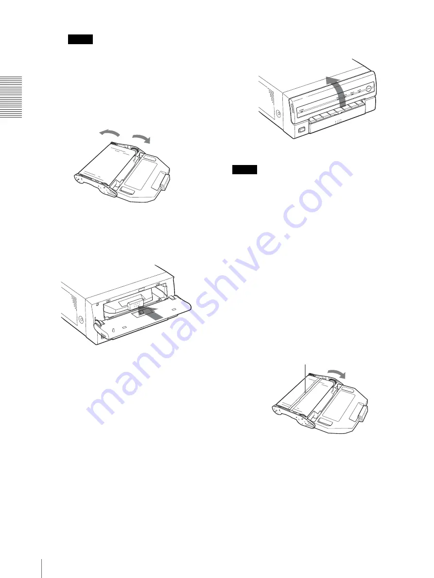
Note

If the ribbon is left slack, it may be damaged 
when the ink ribbon cartridge is inserted into 
the printer.

5

Insert the ink ribbon cartridge until it stops.

If the ink ribbon cartridge cannot be 
inserted

In such a case, close the ribbon door, and turn the 
power off, then back on again. Insert the ink ribbon 
cartridge again.

6

Close the ribbon door.

Notes

When handling the ink ribbon:

• Do not rewind the ink ribbon for reuse.
• When handling the ink ribbon, be careful not to touch 

the surface of the ink ribbon. Dust or finger prints are 
likely to cause unsatisfactory printing or malfunction 
of the head.

When storing ink ribbon:

• Avoid placing the ink ribbon in a location subject to:

– high temperatures
– high humidity
– excessive dust
– direct sunlight

• Store a partially used ink ribbon in its original 

packaging.

If your ink ribbon should tear

Repair the tear with transparent tape. There should be no 
problem with using the remaining portion of the ribbon.

Turn the gears in the direction of the 
arrows until any slack is eliminated 
and the magenta section of the ink 
ribbon appears.

Transparent tape

Turn the gray gear of the spool that takes up the 
ink ribbon in the direction of the arrow to remove 
any slack until the transparent tape cannot be 
seen.

Summary of Contents for UP-D55

Page 1: ...2 059 514 13 1 Digital Color Printer 2004 Sony Corporation UP D55 Instructions for Use ...

Page 2: ...ty to operate this equipment All interface cables used to connect peripherals must be shielded in order to comply with the limits for a digital device pursuant to Subpart B of Part 15 of FCC Rules For the customers in Canada This unit has been certified according to Standard CAN CSA C22 2 No 60601 1 For the customers in the U S A and Canada When you use this product connected to 240 V single phase...

Page 3: ...the UP D55 Warning If the UP D55 should be used adjacent to or stacked with other equipment it should be observed to verify normal operation in the configuration in which it will be used Guidance and manufacturer s declaration electromagnetic emissions The UP D55 is intended for use in the electromagnetic environment specified below The customer or the user of the UP D55 should assure that it is u...

Page 4: ...mode 2 kV common mode 1 kV differential mode 2 kV common mode Mains power quality should be that of a typical commercial or hospital environment Voltage dips short interruptions and voltage variations on power supply input lines IEC 61000 4 11 5 UT 95 dip in UT for 0 5 cycle 40 UT 60 dip in UT for 5 cycles 70 UT 30 dip in UT for 25 cycles 5 UT 95 dip in UT for 5 sec 5 UT 95 dip in UT for 0 5 cycle...

Page 5: ...transmitters as determined by an electromagnetic site survey a should be less than the compliance level in each frequency range b Interference may occur in the vicinity of equipment marked with following symbol NOTE 1 At 80 MHz and 800 MHz the higher frequency range applies NOTE 2 These guidelines may not apply in all situations Electromagnetic propagation is affected by absorption and reflection ...

Page 6: ...please refer to the addresses provided in the separate service or guarantee documents Recommended separation distances between portable and mobile RF communications equipment and the UP D55 The UP D55 is intended for use in an electromagnetic environment in which radiated RF disturbances are controlled The customer or the user of the UP D55 can help prevent electromagnetic interference by maintain...

Page 7: ...10 USB Port Connection 10 Installing the Printer Driver 10 Operation Before Printing 12 Loading an Ink Ribbon Cartridge 12 Inserting the Paper Tray 15 Printing 16 Miscellaneous Precaution 18 Safety 18 Installation 18 Before Transporting the Printer 18 Cleaning 18 Ink Ribbon and Paper 19 Specifications 19 Troubleshooting 20 Indicators on the Ribbon Door 21 If the Paper Jams 22 Index 24 ...

Page 8: ...OWER switch of the printer is set to ON B PRINT indicator 21 Lights while the printer is printing C ALARM indicator 21 Lights in orange in case of paper jamming or occurrence of any other problem D RIBBON indicator 21 Lights when a problem for ink ribbon occurs E PAPER indicator 21 Lights when a problem for paper occurs The printer allows you to check the printer operating condition according to t...

Page 9: ...ices for use in the medical environments on page 2 C USB cable clamp Used to secure the USB cable D USB connector 10 Connects to a computer or another USB peripheral device with a USB cable supplied E Switch Not used at present Supplied Accessories The printer is packed together with the following accessories Check that nothing is missing from your package Notes Retain the original carton and pack...

Page 10: ...r connection to a USB hub USB Port Connection Installing the Printer Driver Install the printer driver provided with the printer For detailed instructions on how to install the printer driver refer to the Readme txt file on the printer driver installer disc About USB Universal Serial Bus Specification Revision 2 0 The UP D55 complies with the USB 2 0 specification USB 2 0 is a newer standard than ...

Page 11: ... conform to USB 2 0 or all USB 2 0 extension boards extension cards cannot be guaranteed Note When the UP D55 is connected to the computer with the power turned on do not turn your computer to standby mode suspend status or in pause mode Doing so may cause a malfunction of the operation ...

Page 12: ...lder and to load the ink ribbon cartridge in the printer When you use the printer for the first time start the operation to load the ink ribbon cartridge from step 4 Notes When you use the printer for the first time the thermal head may be out of position Before attempting to load the ink ribbon cartridge turn on the power under the condition where the ribbon door is closed so that the thermal hea...

Page 13: ... the ink ribbon in the direction of the arrow remove the spool from the side with the gray gear Pushing the ink ribbon spool that sends the ink ribbon in the direction of the arrow remove the spool from the side with the white gear Gear cover To avoid dropping the ink ribbon make sure that you hold it firmly 2 Press the other side of the ink ribbon until you hear it click into place 1 Press the wh...

Page 14: ... Dust or finger prints are likely to cause unsatisfactory printing or malfunction of the head When storing ink ribbon Avoid placing the ink ribbon in a location subject to high temperatures high humidity excessive dust direct sunlight Store a partially used ink ribbon in its original packaging If your ink ribbon should tear Repair the tear with transparent tape There should be no problem with usin...

Page 15: ...he paper tray to remove it 2 Place the paper in the paper tray so that the printing surface faces up with the protection sheet on top Notes Do not add only the paper When the paper supply has been exhausted replace both the ink ribbon and paper at the same time If you add paper while printing this may cause the paper jam When handling the paper do not touch the printing surface Dust or finger prin...

Page 16: ...es 12 and 15 Ensure that the printer driver has been installed See page 10 1 Press the POWER switch to turn the printer on The POWER indicator lights PRINT ALARM RIBBON and PAPER indicators light at the same time then all of them go out Notes Turn the printer on first Do not turn the computer off and on while it is accessing a hard or floppy disk 2 Turn on the power of the computer 3 Execute the p...

Page 17: ... PAPER and or RIBBON indicator light For details see Indicators on the Ribbon Door on page 21 If the paper or ink ribbon runs out during printing The printer stops the printing operation Load the paper into the paper tray and the ink ribbon Printing of remaining copies is automatically started To stop the printing multiple copies of identical printouts Press the STOP button The printer finishes cu...

Page 18: ... left in a room with a heater that tends to produce large amounts of moisture condensation may form inside the printer In such cases the printer will probably not work properly and may even develop a fault if you persist in using it If condensation forms turn off the power and leave the printer to stand for at least one hour If the printing pack is subjected to wide or sudden changes in temperatur...

Page 19: ...and transport temperature 20 C to 60 C 4 F to 140 F Storage and transport humidity 20 to 90 no condensation allowed Storage and transport pressure 700 hPa to 1 060 hPa Dimensions Approx 280 125 398 mm w h d 11 1 8 5 15 3 4 inches Mass Approx 9 kg 19 lb 13 oz Printing system Sublimation heat transfer printing Printable pixels When printing the full image 2528 1920 dots Total gradation 256 levels ea...

Page 20: ...ER switch of the printer to ON Connections may not be correct tCheck connections and rectify if necessary See page 10 The printer does not print The problem is indicated by the indicators on the ribbon door tSee Indicators on the Ribbon Door on page 21 The printout color is very pale The paper is not loaded correctly tCheck which side of the paper is the printing side then load the paper again See...

Page 21: ...s paper The ink ribbon has torn tRepair the torn ink ribbon See page 14 PAPER Paper has been exhausted tLoad the paper See page 15 Also replace the ink ribbon The paper tray is not installed tInstall the paper tray See page 16 ALARM The ribbon door is open tClose the ribbon door surely Paper has jammed inside the printer tRemove any jammed paper from the printer See page 22 The maximum number of p...

Page 22: ...a jammed sheet slowly pull it straight out If you cannot remove the jammed paper even if you perform the operation in step 2 remove the jammed paper according to instructions described in the following If you can not remove the jammed paper yet 3 Load the paper into the paper tray correctly Notes Do not reuse the jammed paper Discard that paper Use only paper recommended in this manual 4 Re insert...

Page 23: ...r 7 Replace the back cover plate Note When you put it back be careful not to catch your fingers or any other object in the back cover plate 8 Secure the back cover plate using the screws removed in step 4 When using the printer again Confirm the following before using the printer again Confirm that connecting cables and the AC power cord are securely connected Reset the paper tray in the printer C...

Page 24: ...nnot remove 12 loading 12 removing 12 L Location and function of parts and controls front panel 8 rear panel 9 O Operation 12 P Paper notes on storing 16 Paper jams 22 Paper tray inserting 16 Precaution before transporting the printer 18 condensation 18 installation 18 safety 18 Printer driver installing 10 Printing 16 Printing pack available printing pack 19 S Specifications 19 System configurati...

Page 25: ...Sony Corporation ...

Reviews: