background image

15

GB

Hooking Up and Setting Up the Speaker System

Specifying the speaker parameters

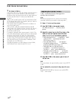
1

Press 

?

/

1

 to turn on the receiver.

2

Press SET UP.

3

Press MENU 

I

/

i

 to select the parameter you want

to adjust.

4

Press MENU +/– to select the setting you want.

The setting is stor

ed automatically

.

5

Repeat steps 3 and 4 until you have set all of the
parameters that follow.

z

Normal speaker and Micro Satellite speaker

Choose NORM. SP. if you’re using normal speakers and MICRO
SP. if you’re using Micro Satellite speakers. If you choose NORM.
SP., you can adjust the speaker size and the sub woofer selection
as mentioned below. However, if you choose MICRO SP., the
speaker size and the sub woofer selection has been configurated
as follows:

Speakers

Settings

Front

SMALL

Center

SMALL

Surround

SMALL

Sub Woofer

YES

You cannot change the configuration if you choose MICRO SP.

For STR-K402, the speaker size and sub woofer selection has been
preset to MICRO SP. according to the supplied speaker system. If
you change the speaker system, choose NORM. SP. to adjust the
speaker size and sub woofer selection.

The setting for Micro Satellite speaker (MICRO SP.) has been
programmed to optimize the sound balance. If you use Sony’s
Micro Satellite speakers, select MICRO SP. When you use Micro
Satellite speaker and the speaker size is set to LARGE, you may
not obtain the correct soundstage. The speaker may also be
damaged at high volume position.

For STR-DE475, the speaker size and sub woofer selection has
been preset to NORM. SP.

The following speaker size setup is applicable for NORM. SP.

45

°

90

°

20

°

A

A

B

C

C

45

°

90

°

20

°

A

A

B

C

C

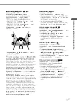
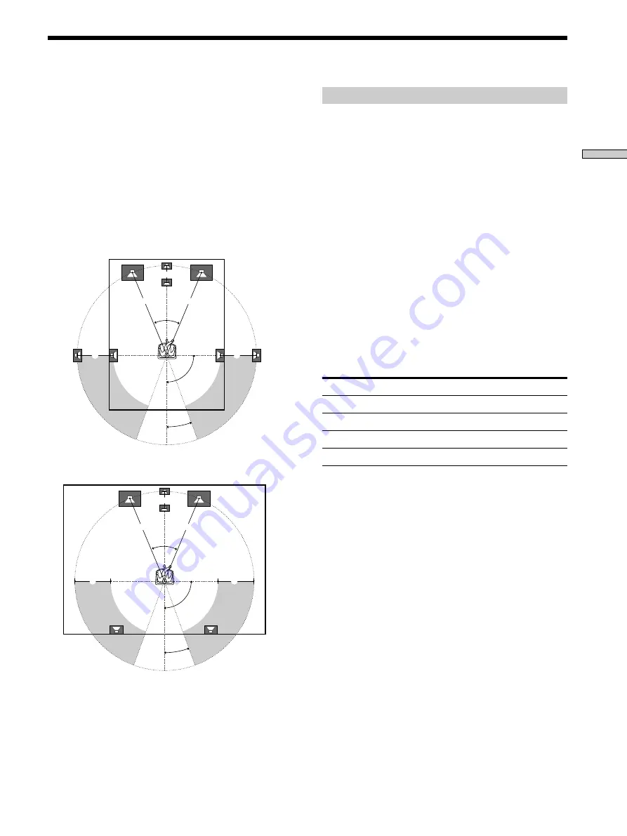
Multi Channel Surround Setup

For the best possible sur

round sound all speakers should

be the same distance fr

om the listening position (

A

).

(However , this unit lets you to place the center speaker up
to 5 feet (1.5 meters) closer (

B

) and the sur round speakers

up to 15 feet (4.5 meters) closer (

C

) to the listening

position.
The fr ont speakers can be placed fr

om 3 to 40 feet (1.0 to

12.0 meters) fr

om the listening position (

A

).)

You can place the sur

round speakers either behind you or

to the side, depending on the shape of your r

oom (etc.).

Note

Do not place the center speaker farther away from the listening
position than the front speakers.

When placing surround speakers to your side

When placing the surround speakers behind you

Summary of Contents for STR-K402 - Fm Stereo/fm-am Receiver

Page 1: ......

Page 2: ...l the cord One blade of the plug is wider than the other for the purpose of safety and will fit into the wall outlet only one way If you are unable to insert the plug fully into the outlet contact your dealer for customers in the United States and Canada only AC power cord must be changed only at the qualified service shop On placement Place the receiver in a location with adequate ventilation to ...

Page 3: ...74 5 974 380 5 978 762 and other world wide patents issued and pending DTS and DTS Digital Surround are registered trademarks of Digital Theater Systems Inc Copyright 1996 2000 Digital Theater Systems Inc All Rights Reserved TABLE OF CONTENTS Hooking Up the Components 4 Unpacking 4 Antenna Hookups 5 Audio Component Hookups 6 Video Component Hookups 7 Digital Component Hookups 8 MULTI CH IN Hookups...

Page 4: ...6 months When the remote no longer operates the receiver replace all batteries with new ones Notes Do not leave the remote in an extremely hot or humid place Do not use a new battery with an old one Do not expose the remote sensor to direct sunlight or lighting apparatuses Doing so may cause a malfunction If you don t use the remote for an extended period of time remove the batteries to avoid poss...

Page 5: ...d Terminals for connecting the antennas C o n n e c t t h e T o t h e AM loop antenna AM terminals FM wire antenna FM 75Ω COAXIAL terminal Antenna Hookups ANTENNA AM FM 75Ω COAXIAL Important If you connect the receiver to an outdoor antenna ground it against lightning To prevent a gas explosion do not connect the ground wire to a gas pipe Notes on antenna hookups To prevent noise pickup keep the A...

Page 6: ...DVD LD IN SURROUND R L R L CENTER VIDEO IN VIDEO IN VIDEO OUT VIDEO IN VIDEO OUT IMPEDANCE USE 8 16Ω IMPEDANCE USE 8 16Ω ANTENNA ANTENNA AM FM 75Ω COAXIAL TV SAT TV SAT MONITOR DVD LD DVD LD SUB WOOFER SUB WOOFER COAXIAL Jacks for connecting audio components C o n n e c t a T o t h e CD player CD jacks MD deck or Tape deck MD TAPE jacks Required cords Audio cords not supplied When connecting a cor...

Page 7: ...t your TV s audio output jacks to the TV SAT AUDIO IN jacks on the receiver and apply sound effects to the audio from the TV In this case do not connect the TV s video output jack to the TV SAT VIDEO IN jack on the receiver If you are connecting a separate TV tuner or satellite tuner connect both the audio and video output jacks to the receiver as shown above Jacks for connecting video components ...

Page 8: ...o the receiver s digital input jacks to bring the multi channel surround sound of a movie theater into your home To enjoy full effect of multi channel surround sound five speakers two front speakers two surround speakers and a center speaker and a sub woofer are required You can also connect an LD player with an RF OUT jack via an RF demodulator such as the Sony MOD RF1 not supplied Digital Compon...

Page 9: ...TI CH IN CENTER and SUB WOOFER jacks Black Black Video cord not supplied One for the DVD LD VIDEO IN jacks etc Yellow Yellow Note When using the connections described below adjust the level of your surround speakers and sub woofer from the DVD player or multichannel decoder Although this receiver incorporates a multi channel decoder it is also equipped with MULTI CH IN jacks These connections allo...

Page 10: ...AGE SELECTOR MULTI CH IN MULTI CH IN DIGITAL DIGITAL CD CD MD TAPE MD TAPE VIDEO VIDEO SPEAKERS SPEAKERS FRONT TV SAT IN OPTICAL DVD LD IN SURROUND R L R L CENTER VIDEO IN VIDEO IN VIDEO OUT VIDEO IN VIDEO OUT IMPEDANCE USE 8 16Ω IMPEDANCE USE 8 16Ω ANTENNA ANTENNA AM FM 75Ω COAXIAL TV SAT TV SAT MONITOR DVD LD DVD LD SUB WOOFER SUB WOOFER COAXIAL AC power cord To a wall outlet Other Hookups VOLTA...

Page 11: ... AM SET UP MENU MENU I i Hooking Up and Setting Up the Speaker System This chapter describes how to hook up your speaker system to the receiver how to position each speaker and how to set up your speakers to enjoy multi channel surround sound Brief descriptions of buttons and control used to set up the speaker system SETUPbutton Presstoenterthesetupmodewhen specifyingspeakertypesanddistances MENUI...

Page 12: ...ub woofer Surround speaker R Surround speaker L Notes on speaker system hookup T wistthestrippedendsofthespeakercor dsabout2 3 inch 10mm Besur etomatchthespeakercor dtothe appr opriateter minalonthecomponents to and to Ifthecor dsar er eversed thesoundwillbe distortedandwilllackbass Ifyouusespeakerswithlowmaximuminputrating adjustthevolumecar efullytoavoidexcessiveoutput onthespeakers Terminals fo...

Page 13: ...ipped cords are touching each other due to excessive removal of insulation After connecting all the components speakers and AC power cord output a test tone to check that all the speakers are connected correctly For details on outputting a test tone see page 18 Ifnosoundishear dfr omaspeakerwhileoutputtinga testtoneoratesttoneisoutputfr omaspeakerotherthan theonewhosenameiscur rentlydisplayedonthe...

Page 14: ...eandplacement page15 Speakerdistance page17 SelecttheMUL TICHINvideosignal page41 Whetherthedisplaytur nsof fornotwhenyoupr ess DIMMER page41 1 MULTI CHANNEL DECODING MASTER VOLUME DISPLAY MULTI CH IN INPUT MODE BASS MUTING A F D ENTER NAME VIDEO DVD LD TV SAT MD TAPE CD TUNER SET UP MENU LEVEL SURR SOUND CONTROL SOUND FIELD MODE 2CH DIMMER PHONES 1 TREBLE TUNING PRESET TUNING MEMORY SHIFT FM MODE...

Page 15: ... adjust the speaker size and sub woofer selection The setting for Micro Satellite speaker MICRO SP has been programmed to optimize the sound balance If you use Sony s Micro Satellite speakers select MICRO SP When you use Micro Satellite speaker and the speaker size is set to LARGE you may not obtain the correct soundstage The speaker may also be damaged at high volume position For STR DE475 the sp...

Page 16: ...oundfields x Front speaker size L R Initialsetting LARGE Ifyouconnectlar gespeakersthatwillef fectively repr oducebassfr equencies select LARGE Nor mally select LARGE Ifthesoundisdistor ted oryoufeelalackofsur round effectswhenusingmultichannelsur roundsound select SMALL toactivatethebassr edir ectioncir cuitr y andoutputthefr ontchannelbassfr equenciesfr omthe subwoofer Whenthefr ontspeakerissett...

Page 17: ...pr operimplementationofthe DigitalCinemaSoundsur roundmodesinthe VIRTUAL soundfields Refertotheillustrationbelow Select HGT LOW ifthelocationofyoursur round speakerscor respondstosection A Select HGT HIGH ifthelocationofyoursur round speakerscor respondstosection B Thissettingonlyaf fectsthesur roundmodesinthe VIRTUAL soundfields Theseparametersar enotavailablewhen Sur round speakersize issetto NO...

Page 18: ... the same time Rotate MASTER VOLUME on the receiver or press MASTER VOL on the remote Multi Channel Surround Setup z About speaker distances This receiver allows you to input the speaker position in terms of distance However it is not possible to set the center speaker farther away than the front speakers Also the center speaker can not be set more that 5 feet 1 5 meters closer than the front spea...

Page 19: ...tomatically we recommend you follow the procedure previously described in this section and adjust the speaker levels from your listening position using the remote control z When setting the volume levels for each speaker Let s assume that you have matched the sound levels of all the speakers using the test tone Although this lays the foundation for high quality surround sound it may be necessary t...

Page 20: ...dphonestothePHONESjack toverifythatsoundisoutputfr omtheheadphones see w PHONESjack onpage23 Ifonlyonechannelisoutputfr omtheheadphones thecomponentmaynotbeconnectedtothe receivercor rectly Checkthatallthecor dsar efully inser tedintothejacksonbothther eceiverandthe component Ifbothchannelsar eoutputfr omtheheadphones thefr ontspeakermaynotbeconnectedtothe receivercor rectly Checktheconnectionofth...

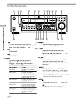
Page 21: ... name appears only when you have assigned one to the component or preset station see page 39 Index name does not appear when only blank spaces have been entered or it is the same as the function button Frequency appears only when the tuner is selected 3 D I M M E R b u t t o n Pressr epeatedlytoadjustthebrightnessofthedisplay Whenyouwanttotur nof fthedisplay setinthe DIM RANGE parameterintheSETUPm...

Page 22: ...ance Specify the front center and surround speaker distances page 17 Dimmer range Specify the display to turn off when you press the DIMMER button several times page 47 MULTI CH IN Specify the video input to be video input used with the audio signals from the MULTI CH IN jacks page 47 6 M U L T I C H A N N E L D E C O D I N G i n d i c a t o r Thisindicatorlightsupwhentheunitisdecoding signalsr ec...

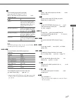
Page 23: ...ayer or LD player turn on the TV and set the TV s video input to match the component you selected qd M A S T E R V O L U M E c o n t r o l Aftertur ningonthecomponentyouselected r otateto adjustthevolume q fM U T I N G b u t t o n Presstomutethesound MUTINGappearsonthe displaywhenthesoundismuted qg S O U N D F I E L D UsetheSOUNDFIELDbuttonstoenjoysur round sound Fordetails see EnjoyingSur roundSo...

Page 24: ...emodesalsopr ovidesoundef fectscommonlyfound inmovietheaters Thevirtualsoundmodescontaincompellingapplications oftheSonyDigitalCinemaSounddigitalsignal processingtechnology Theyshiftthesoundawayfr om theactualspeakerlocationstosimulatethepr esenceof several virtual speakers Themusic etc soundmodesar edesignedforusewith standar daudiosour cesandTVbr oadcasts Theyadd reverberationtothesour cesignalt...

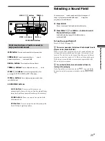
Page 25: ...gital discs are labeled with the logo and Dolby Surround encoded programs are labeled with the A logo Brief descriptions of buttons used to enjoy surround sound LEVELbutton Presstocustomizethelevelparameters SURRbutton Presstocustomizethesur round parametersinthecur rentsoundfield BASS buttons Presstoadjustthetone bass TREBLE buttons Presstoadjustthetone tr eble MENU buttons Usetoselectparametersa...

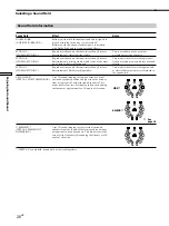
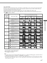
Page 26: ...fects Reproduces the sound characteristics of Sony Pictures Entertainment s classic editing studio Reproduces the sound characteristics of Sony Pictures Entertainment s mixing studio which is one of the most up to date facilities in Hollywood Reproduces the sound characteristics of Sony Pictures Entertainment s BGM recording studio Uses 3D sound imaging to create an array of virtual surround speak...

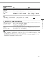
Page 27: ...ass signal Reproduces the acoustics of a rectangular concert hall Reproduces the acoustics of a jazz club Reproduces the acoustics of a 300 seat live house Obtains maximum audio impact from video game software Automatically detects the type of audio signal being input Dolby Digital Dolby Pro Logic or standard two channel stereo and performs the proper decoding if necessary This mode presents the s...

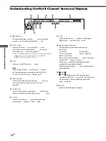
Page 28: ...seindicatorslightupwhenusingther eceiverto tuneinradiostations etc Seepages34 37fortuner operations 5 D RANGE Lightsupwhendynamicrangecompr essionisactive Seepage32toadjustthedynamicrangecompr ession 6 COAX Lightsupwhenthesour cesignalisadigitalsignal beinginputthr oughtheCOAXter minal 7 OPT Lightsupwhenthesour cesignalisadigitalsignal beinginputthr oughtheOPTter minal 8 Playbackchannelindicators ...

Page 29: ...t 1 0 2 0 3 0 2 1 3 1 2 2 3 2 2 0 DOLBY DIGITAL 1 0 DTS 1 0 DOLBY PRO LOGIC PCM XX kHz DIGITAL C C DOLBY DIGITAL 2 0 DTS 2 0 DOLBY DIGITAL 3 0 DTS 3 0 DOLBY DIGITAL 2 1 DTS 2 1 DOLBY DIGITAL 3 1 DTS 3 1 DOLBY DIGITAL 2 2 DTS 2 2 DOLBY DIGITAL 3 2 DTS 3 2 DOLBY DIGITAL 2 0 DIGITAL C dts C DIGITAL C dts C DIGITAL C dts C L C R L C R DIGITAL L C R L C R DIGITAL L C R L C R DIGITAL L C R L C R L R L R...

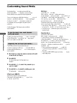
Page 30: ...t 4 Press MENU to select the setting you want Thesettingisstor edautomatically Effect level EFFECT Initialsetting dependsonsoundfieldmode Thisparameterletsyouadjustthe pr esence ofthe currentsur roundef fect Wall type Initialsetting W ALLMID Whensoundisr eflectedof fsoftmaterial suchasa curtain thehighfr equencyelementsar er educed Ahar d wallishighlyr eflectiveanddoesnotsignificantlyaf fect thefr...

Page 31: ...ng SURR0dB Letsyouadjustlevelofthesur round leftandright speakers Thelevelcanbeadjustedin1dBstepsfr om 10dBto 6dB Thesesettingscanalsobeadjusteddir ectlyusingthe suppliedr emote See Adjustingthespeakervolume page18 Center level Initialsetting CTR 0dB Letsyouadjustthelevelofthecenterspeaker Thelevelcanbeadjustedin1dBstepsfr om 10dBto 6dB Sub woofer level Initialsetting S W 0dB Letsyouadjustthelevel...

Page 32: ...dard compression but because many sources have only light compression you may not notice much difference when using COMP 0 1 0 9 Therefore we recommend using the COMP MAX setting This greatly compresses the dynamic range and allows you to view movies late at night at low volumes Unlike analog limiters the levels are predetermined and it provides a very natural compression Adjusting the bass treble...

Page 33: ...MA STUDIO B r r r r r r r CINEMA STUDIO C r r r r r r r V MULTI DIMENSION r r r r r r V SEMI M DIMENSION r r r r HALL r r r r r r r r r JAZZ CLUB r r r r r r r r r LIVE HOUSE r r r r r r r r r GAME r r r r r r r r r MULTI CH IN r r r r r D RANGE BASS TREBLE COMP 2CH r r A F D r r NORMAL SURROUND r r CINEMA STUDIO A r r CINEMA STUDIO B r r CINEMA STUDIO C r r V MULTI DIMENSION r r V SEMI M DIMENSIO...

Page 34: ...Ifyoudon tknowthefr equencyofthestationyouwant youcanletther eceiverscanallavailablestationsinyour area seepage36 Preset Tuning AfteryouhavetunedinstationsusingDir ectT uningor AutomaticT uning youcanpr esetthemtother eceiver seepage37 Thenyoucantuneinanyofthestations directlybyenteringits2 charactercode seepage37 Up to30FMorAMstationscanbepr eset Ther eceiverwill alsoscanallthestationsthatyouhave...

Page 35: ...hisbuttontoenterafr equencydir ectly usingthenumericbuttons Numericbuttons Presstoenteranumericvaluewhen inputtingthefr equencydir ectly presettingradiostations ortuningtopr esetstations MULTI CHANNEL DECODING MASTER VOLUME DISPLAY MULTI CH IN INPUT MODE BASS MUTING A F D ENTER NAME VIDEO DVD LD TV SAT MD TAPE CD TUNER SET UP MENU LEVEL SURR SOUND CONTROL SOUND FIELD MODE 2CH DIMMER PHONES 1 TREBL...

Page 36: ...ve other stations z If you try to enter a frequency not covered by the tuning interval The entered value is automatically rounded up or down This tuning scale for direct tuning differs depending on the area code as shown in the following table For details on area codes see page 3 Area code FM tuning scale AM tuning scale U CA 50 kHz 10 kHz can be changed to 9 kHz E2 E3 TW 50 kHz 9 kHz can be chang...

Page 37: ...EMORY again to store the station If MEMOR Y goesoutbefor eyoucanstor ethe station star tagainfr omStep3 7 Repeat Steps 2 to 6 to preset another station To change a preset number to another station DoSteps1to6topr esetthenewstationtothenumber Note If the AC power cord is disconnected for about one week all the preset stations will be cleared from the receiver s memory and you will have to preset th...

Page 38: ...UNER NAME MENU I i MENU SET UP ENTER Other Operations Brief descriptions of buttons that appear in this chapter NAMEbutton Presstonamepr esetstationsorpr ogram sour ces MENU buttons Usetoselectcharacterswhen namingpr esetstationsorpr ogramsour ces MENU buttons Usetomovethecursorwhen namingpr esetstationsorpr ogramsour ces TUNERbutton Presstoselectthetuner SETUPbutton Presstoenterthesetupmode ENTER...

Page 39: ...eck then start playback on the playback component Naming Preset Stations and Program Sources Youcanenteraname indexname ofupto8characters forpr esetstationsandpr ogramsour ces Thesenames for example VHS appearinther eceiver sdisplaywhena stationorpr ogramsour ceisselected Notethatnomor ethanonenamecanbeenter edforeach presetstationorpr ogramsour ce Thisfunctionisusefulfordistinguishingcomponentsof...

Page 40: ...tead of the audio from the original medium To resume audio recording from the original medium select the video source again Notes You cannot record a digital audio signal using a component connected to the analog MD TAPE OUT or VIDEO OUT jacks Sound adjustments do not affect the signal output from the MD TAPE OUT or VIDEO OUT jacks When MULTI CH IN is selected audio signals are not output from MD ...

Page 41: ...Dbydefault 1 Press SET UP 2 Press MENU to select MULTI CH IN VISUAL 3 Press MENU to select the video input you want Set the display to turn off Thisparameterletsyouspecifywhetherornotthedisplay tur nsof fwhenyoupr esstheDIMMERbuttonseveral times When WIDE isselected youcansetthedisplay totur nof f butwhen NARROW isselected youcannot setthedisplaytotur nof f Thedefaultsettingissetto NARROW 1 Press ...

Page 42: ... t cir cuitpr oblemand turnonthepoweragain The left and right sounds are unbalanced or reversed Checkthatthespeakersandcomponentsar e connectedcor rectlyandsecur ely Adjustfr ontbalanceparameterintheLEVEL menu Severe hum or noise is heard Checkthatthespeakersandcomponentsar e connectedsecur ely Checkthattheconnectingcor dsar eawayfr oma transfor merormotor andatleast10feet 3meters awayfr omaTVseto...

Page 43: ...seepages36and45 Nostationshavebeenpr esetorthepr esetstations havebeenclear ed whentuningbyscanningpr eset stations Pr esetthestations seepage37 PressDISPLA Ysothatthefr equencyappearsin thedisplay The surround effect cannot be obtained Makesur ethesoundfieldfunctionison pr ess SOUND FIELD MODE PCM kHz appears on the display Thesamplingfr equencyismor ethan48kHz Changetheinputplayersettingto48kHz ...

Page 44: ...de U CA Rated Power Output at Stereo mode 8ohms40Hz 20kHz THD0 09 80W 80W Reference Power Output 8ohms1kHz THD0 7 Front 1 80W ch Center 1 80W Surround1 80 W ch Models of area code CN Rated Power Output at Stereo mode 8ohmsat1kHz THD0 7 75W 75W at220VAC 50Hz 80W 80W at230VAC 50Hz Reference Power Output 8ohmsat1kHz THD10 at230V AC 50Hz Front 1 90W ch Center 1 90W Surround1 90 W ch Models of other ar...

Page 45: ... reset the scale to 10 kHz or 9 kHz repeat the procedure Video section Inputs Video 1Vp p75ohms Outputs Video 1Vp p75ohms General System T unersection PLLquartz locked digitalsynthesizer system Preamplifiersection Low noiseNFtype equalizer Poweramplifier section Pure complementar y SEPP Power requirements Modelsofar eacodeU CA 120VAC 60Hz Modelsofar eacode CN 220 230VAC 50 60 Hz Modelsofar eacodeA...

Page 46: ...dspeakersanda centerspeaker Thesur roundspeakers outputmonauralsound Dolby Digital Thissoundformatformovietheaters ismor eadvancedthanDolbyPr o LogicSur round Inthisfor mat the surroundspeakersoutputster eo soundwithanexpandedfr equency rangeandasubwooferchannelfor deepbassisindependentlypr ovided Thisformatisalsocalled 5 1 becausethesubwooferchannelis countedas0 1channel sinceit functionsonlywhen...

Page 47: ...s LFE MIX LEVEL OFF or 20 dB to 0 dB in 1 dB steps LEVEL button SURR LEVEL between 10 dB to 6 dB in 1 dB steps 31 L R FRONT LARGE or SMALL 15 C CENTER LARGE SMALL or NO SL SR SURR LARGE SMALL or NO SL SR SURR PL XXX PL SIDE or PL BEHD SL SR SURR HGT XXX HGT LOW or HGT HIGH S W SUB WOOFER S W YES or S W NO L R FRONT XX X ft m between 3 feet 1 0 meters and 40 feet 12 0 meters in 1 foot 0 1 meter ste...

Page 48: ... MD deck over 10 Tape deck LD player VCD player Remote Button Operations Function ENTER TV VCR SAT After selecting a channel Tape deck disc or track using the LD player numeric buttons press VCD player to enter the value MD deck DAT deck SHIFT Receiver Press repeatedly to select a memory page for presetting radio stations or tuning to preset stations TV Selects the channel entry mode either one or...

Page 49: ...utes the sound from the receiver TEST TONE Receiver Press to output test tone MAIN MENU Receiver Press this button repeatedly to select one of the two cursor modes LEVEL and SURROUND Remote Button Operations Function MASTER VOL Receiver Adjusts the master volume of the receiver MENU Receiver Selects a menu item MENU Receiver Makes adjustment or change the setting MENU DVD Displays DVD menu F f G g...

Page 50: ... buttons Numeric buttons P p DISC 9 0 10 0 7 8 9 4 5 6 1 2 3 ENTER CD SACD TUNER VIDEO AUX MD TAPE VIDEO 2 PHONO VIDEO 1 VIDEO 3 SYSTEM STANDBY FUNCTION SHIFT POSITION DISPLAY MODE JUMP A F D MUTING 2CH OFF WIDE P IN P SWAP D SKIP CH PRESET SUB CH ANT TV VTR TV VIDEO MULTI CH 2 CH DIRECT SOUND FIELD MAIN MENU MENU MASTER VOL TEST TONE D TUNING RETURN MENU ENTER TITLE f F G g SLEEP AV 1 1 DVD LD TV...

Page 51: ...ts 8 speaker system 12 video components 7 I J K Indexing See Naming L M Labeling See Naming N O Naming preset stations 39 program sources 39 P Q Parameter 31 33 Preset stations how to preset 37 how to tune 37 Preset tuning 37 R Receiving broadcasts automatically 36 directly 36 preset stations 37 Recording on an audio tape or MD 39 on a video tape 40 S Scanning preset stations See Preset tuning rad...

Reviews: