background image

Viewing Settings and Indications in the Viewfinder

62

Chap

ter
 3

  Ba
s

ic

 Ad

jus
tme
nt

s

 an
d Set

tings

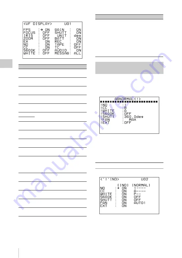
An ABNORMAL< ! > screen like the one shown 
below appears if you press the CANCEL/
STATUS button when the basic status indications 
are displayed in the viewfinder. 

This screen allows you to check for items that are 
set to non-standard settings.
You can select the items to display and define 
non-standard settings on the <‘!’ IND> page of 
the Camera >USER (OPERATION) menu.

Setting the ABNORMAL<!> indications 

For each item, select ON in the [IND] column if 
you want that item to appear in the 
ABNORMAL<‘!’> screen.
Specify the standard setting in the [NORMAL] 
column.

Item

Setting

FPS

Set to ON to obtain the frame rate 
indication 

1

.

FOCUS

Set to ON to display the focus position 
indication 

5

.

IRIS

Set to ON to display the F value 
indication 

qf

.

ZOOM

Set to ON to display the zoom position 
indication 

6

.

EX

Set to ON to display the lens extender 
indication 

2

.

ND

Set to ON to display the optical filter 
indications 

9

.

CC

5600K

Set to ON to display the 5600 
indication 

8

.

WHITE

Set to ON to display the white balance 
memory indication 

7

.

GAIN

Set to ON to display the gain value 
indication 

q;

.

SHUTT

Set to ON to display the shutter 
indication 

qa

.

UNIT

Select the unit for the shutter 
indication.

deg:

 Shutter angle (default)

sec:

 Shutter speed (sec)

BATT

Set to ON to display the battery 
indication 

4

.

REC

Set to ON to display the recording 
mode indication 

3

.

TAPE

Set to ON to display the tape 
remaining indication 

qd

.

TC

Set to ON to display the timecode 
indication 

qj

.

AUDIO

Set to ON to display the audio level 
meters 

qs

.

<VF DISPLAY> page

MESSAG

Select the type of messages to be 
displayed in the message area 

qh

.

ALL: 

Display all messages

AT:

 Display auto setup information 

and higher

WRN:

 Display warning messages and 

higher

OFF: 

Display warning messages of 

the highest level only

Viewing the ABNORMAL <!> 
Display

Item

Setting

<‘!’ IND> page

Summary of Contents for SRW-9000

Page 1: ...9000 SY 4 160 062 04 1 Printed in Japan 2011 01 32 2009 HD CAMCORDER SRW 9000 HD SDI EXPANSION BOARD HKSR 9001 PICTURE CACHE BOARD HKSR 9002 FILTER SERVO UNIT HKSR 9004 OPERATION MANUAL English 1st Edition Revised 3 HD CAMCORDER SRW 9000 4160062040 ...

Page 2: ...ould void your authority to operate this equipment All interface cables used to connect peripherals must be shielded in order to comply with the limits for a digital device pursuant to Subpart B of Part 15 of FCC Rules This device complies with Part 15 of the FCC Rules Operation is subject to the following two conditions 1 this device may not cause harmful interference and 2 this device must accep...

Page 3: ...ion erklærer herved at følgende udstyr SRW 9000 HD Camcorder overholder de væsentlige krav og øvrige relevante krav i direktiv 1999 5 EF For yderligere information gå ind på følgende hjemmeside http www compliance sony de Sony Corporation vakuuttaa täten että SRW 9000 HD Camcorder tyyppinen laite on direktiivin 1999 5 EY oleellisten vaatimusten ja sitä koskevien direktiivin muiden ehtojen mukainen...

Page 4: ...onfier l entretien de l appareil qu à un personnel qualifié Une pression acoustique excessive en provenance des écouteurs ou du casque peut provoquer une baisse de l acuité auditive Pour utiliser ce produit en toute sécurité évitez l écoute prolongée à des pressions sonores excessives Pour les clients au Canada Cet appareil numérique de la classe B est conforme à la norme NMB 003 du Canada Pour le...

Page 5: ...den verursachen Um dieses Produkt sicher zu verwenden vermeiden Sie längeres Hören bei sehr hohen Schalldruckpegeln Für Kunden in Europa Dieses Produkt besitzt die CE Kennzeichnung und erfüllt die EMV Richtlinie der EG Kommission Angewandte Normen EN55103 1 Elektromagnetische Verträglichkeit Störaussendung EN55103 2 Elektromagnetische Verträglichkeit Störfestigkeit Für die folgenden elektromagneti...

Page 6: ...apter 2 Preparations Connecting a Power Supply 28 Using a Battery Pack 28 Using AC Power 29 Turning on the Power 29 Checking the Power and Voltage 29 Mounting the Lens 30 Attaching the Viewfinder 32 Connecting Audio Input 33 Using a Microphone 33 Connecting Line Input Audio Equipment 33 Connecting an Audio Multiplexer MUX to the AUX IN Connector When Using the HKSR 9001 34 Mounting on a Tripod 35 ...

Page 7: ...h 51 Adjusting the Brightness of the Subdisplay 52 Selecting Gamma Tables 52 Selecting Pages to Display in the Subdisplay 52 Adjusting the Black Balance 54 Adjusting the White Balance in Custom Mode 55 Setting the Camera Outputs 56 Selecting Video Output Signals for the Connectors 56 Setting the Monitor Picture 57 Outputting Color Bars 59 Viewing Settings and Indications in the Viewfinder 60 Viewi...

Page 8: ...g Cassettes 80 Preventing Accidental Erasure 81 Recording 81 Setting System Signal Format 81 Making Audio Signal Settings 83 Setting Recording Audio Levels 84 Making Timecode and User Bits Settings 85 Shooting 87 Continuous Recording 88 Playback Checking the Recording 89 Preparing for Playback 89 Checking the Last Three Seconds of the Recording Recording Review 91 Checking the Recording on a Color...

Page 9: ...ngs Camera Menu Configuration 111 Basic Camera Menu Operations 113 Displaying Setting Pages 114 Setting Menu Items 115 Camera Menu List 117 OPERATION Menu 117 PAINT Menu 128 MAINTENANCE Menu 138 FILE Menu 146 DIAGNOSIS Menu 151 Editing the USER Menu 152 Creating New Pages 152 Returning the USER Menu to the Factory Defaults 155 VTR Menu Operations 155 Displaying VTR Menus 155 Changing Menu Settings...

Page 10: ...B750 181 Connection 181 Operating the Camera Menu 181 Monitoring the Camera Image 182 Warning System 183 Warning Error Messages 185 Warning and Error Messages Related to the Camera Module 185 Error Messages Related to the VTR Module 186 Warning Messages Related to the VTR Module 187 Precautions 190 About a Memory Stick 191 Maintenance and Inspections 192 Head Cleaning 192 Condensation 192 Note Abo...

Page 11: ...ate support The unit supports a variety of 1080 formats for the production of high end content such as movies commercials and broadcast programming 1080 1920 progressive formats 23 98PsF 24PsF 25PsF 29 97PsF 50P 59 94P 1080 1920 interlaced formats 50i 59 94i RGB 4 4 4 shooting and recording Because of its high compatibility with computer graphics and digital compositing systems the RGB 4 4 4 forma...

Page 12: ...unction 1 SR Motion is a trademark of Sony Corporation Timer Rec When the optional HKSR 9002 Picture Cache Board is installed a Timer Rec function is available on this unit This allows you to utilize the memory in the option board to shoot images at a specified interval This enables time lapse recording and recording over long periods Cache Rec When the optional HKSR 9002 Picture Cache Board is in...

Page 13: ... are using the optional HDVF C30WR HD Electronic Viewfinder For more information about attaching connecting and using additional equipment and accessories see Chapter 2 Preparations page 28 as well as the operation manuals for the connected equipment Viewfinder Viewfinder related equipment Example System Configuration Name Model name HD Electronic Viewfinder HDVF 20A C30WR Name purpose Magnificati...

Page 14: ... name UHF Synthesized Tuner Unit WRR 861 Microphone ECM 678 674 Microphone Holder CAC 12 HDSDI 4 Channel Analog Audio Embedder Disembedder HD10AMA AJA Video Name Model name AC Adaptor AC DN2B DN10 Name Model name Tripod Attachment VCT 14 Bridge Plate BP 8 ARRIFLEX Name Model name HD SDI Expansion Board HKSR 9001 Picture Cache Board HKSR 9002 Filter Servo Unit HKSR 9004 Name purpose Magnification P...

Page 15: ...see Adjusting the White Balance in Custom Mode page 55 d LENS connector 12 pin If you mount an optional lens with a cable connect the cable to this connector You can control the functions of the lens through this connector Note Do not connect a device whose maximum rated current is 1 A or higher to the LENS connector e Lens mount cap Cover the lens mount with this cap when a lens is not attached T...

Page 16: ...he AP 1 Assistant Panel Optional page 38 e Power ON OFF 1 switch and indicator Push the switch to the ON side to power the unit on the indicator lights Push it to the OFF side to power the unit off the indicator goes out f EARPHONES jack and LEVEL knob Use the jack to attach earphones or stereo headphones equipped with a stereo miniplug for use in monitoring audio during recording and playback Adj...

Page 17: ...h the switch downward to the AUTO BLK BAL side to start the auto black balance adjustment You can use the Camera menu to assign a function to the 4 position upper position This position is set to OFF disabled when the unit is shipped from the factory For details see Assigning Functions to Assignable Buttons Switch page 51 e RUN button and indicator Starts and stops recording The indicator lights d...

Page 18: ...els settings made in the subdisplay and viewfinder or returns the display to a previous state When the Camera menu is not displayed you can press this button to display information about the status of the unit in the subdisplay and viewfinder See Viewing Settings and Indications in the Viewfinder page 60 for details about the status information that appears c Subdisplay Displays the Camera menu an...

Page 19: ... Camera menu see page 56 g DC OUT DC power output connector 4 pin male Supplies 12 V DC power You can connect the power cord of the WRR 861 UHF Synthesized Tuner Unit to this connector h DC IN 11 17V DC power input connector 4 pin Connect the DC power cord of an AC DN2B DN10 AC Adaptor For details see Connecting a Power Supply page 28 i AUDIO IN audio input CH 1 CH 2 connectors XLR type 3 pin fema...

Page 20: ... 1 Assistant Panel or the CAC 12 Microphone Holder For details see Attaching the AP 1 Assistant Panel Optional page 38 or Using a Microphone page 33 d Cable holder attachment screws Attach the supplied cable holder to hold the cable of the control panel or the optional AP 1 Assistant Panel e Accessory attachment screw holes You can attach accessories to the two screw holes 3 8 1 1 4 1 f EJECT butt...

Page 21: ... OFF During recording only the STOP button and PAUSE button are enabled All buttons are enabled when the unit is not in recording mode When the KEY INHI item in the SYSTEM Setup menu is set to MAP the operation buttons follow the settings of the LOCAL KEYMAP item d LIGHT switch The backlight comes on when this is set to ON e ADJUST knob Use to adjust audio levels etc f SELECT ENTER dial When a men...

Page 22: ...es for about 10 seconds and then stops When SYSTEM Setup SERVO EOS MODE is set to LONG the 10 second search time limit described above does not apply Once playback starts the search continues until the recording end point is found For details see Continuous recording in other cases page 88 Pressed with recording paused Plays back the most recently recorded material and then returns to recording pa...

Page 23: ... recent search was interrupted Executes reverse direction searches With each press the search speed changes in the order 2 t 5 t 8 t 2 normal speed If a search is interrupted by another operation the next search is performed at the speed in effect at the time of the interruption Note When you are using the unit at the 880 Mbps recording rate 8 normal speed search is disabled For details on recordi...

Page 24: ...ns 4 to 7 are replaced by the display shown in section 9 This manual refers to the screen shown below as the HOME screen PAUSE button and indicator Pauses tape transport The indicator flashes during pause To resume tape transport press the button again Cues up a time data position specified with FUNC REC buttons or SYSTEM Setup EDIT IN POINT in the VTR menu and stops The specified time data Mark I...

Page 25: ...r SYSTEM Setup EDIT IN POINT in the VTR menu it is displayed in the format IN xx xx xx xx beneath right side the time data for the current tape position When no Mark In data has been set IN appears When TC Setup OTHERS MAIN LTC Delay and or TC Setup OTHERS MAIN VITC Delay in the VTR menu are set to something other than NO Delay IN DLY appears beneath to the left side the time data of the current p...

Page 26: ... SR Motion With HKSR 9002 Installed page 97 for more information about the SR Motion function j HDSDI output When the optional HKSR 9001 is installed displays the signal formats of monitor output MON and the output of the HD SDI OUT A B connectors OUT The display switches when you press the HOME button with the FUNC button held down See What Are Dual Link and 3G page 195 for more information about...

Page 27: ...Locations and Functions of Parts 27 Chapter 1 Overview AP 1 cable while operating the subdisplay If a symbol is shown on the subdisplay register the setting before disconnecting or connecting the cable ...

Page 28: ...peration manual The battery pack may not be recharged fully if you charge it immediately after use while it is still warm Remove the battery pack if the unit will be out of use for an extended period WARNING Batteries shall not be exposed to excessive heat such as sunshine fire or the like To attach the battery pack 1 Press the battery pack against the back of the unit aligning the line on the sid...

Page 29: ...the power goes off To check the type of power being used A battery mark appears in the lower left of the control panel display when power is being supplied from the battery attachment section A power plug mark appears when an AC adaptor is selected as the power supply Note that this mark does not reflect the actual type of power being used but reflects the settings of the following VTR menu items ...

Page 30: ...ewing Settings and Indications in the Viewfinder page 60 For details on the warning tone see Warning System page 183 Use an optional lens that conforms to the B4 2 3 lens mount For details on handling the lens refer to the operation manual for the lens 1 Push the lens mount lever up and remove the lens mount cap from the lens mount 2 Align the center pin on the lens with the notch in the lens moun...

Page 31: ...he flange focal length 1 is necessary in the following situations When you attach a lens for the first time When you exchange lenses When during zooming the focus is not sharp in both telephoto and wide angle mode 1 Flange focal length The distance between the lens mount attachment plane and the imaging plan Note The positions of the controls for adjusting the flange focal length vary somewhat fro...

Page 32: ...ttach it at a lower position use the 2 5 mm wrench to loosen the three screws that secure the viewfinder plate remove the viewfinder plate and attach the viewfinder directly 2 Fit the viewfinder to the viewfinder shoe and slide the viewfinder horizontally The viewfinder stopper slides down automatically 3 Set the viewfinder to the most convenient position tighten the viewfinder positioning ring 1 ...

Page 33: ...phone to the microphone holder refer to the operation manual for the microphone Notes If the input level on this unit is not at an appropriate setting for the microphone sensitivity loud sounds may be distorted and the signal to noise ratio may be affected The AUDIO IN CH 1 and CH 2 connectors are female XLR connectors 3 pin to enable them to provide a phantom 48 V power supply If the microphone c...

Page 34: ...up FORMAT INPUT SEL in the VTR menu is set to AUX Input it is not possible to multiplex audio signals into HDSDI signals because there is a phase difference between HDSDI outputs and AUX IN inputs To input audio signals multiplex them into external HDSDI signals see the next section Multiplexing audio signals into external HDSDI signals Multiplexing into external HDSDI signals Set REFERENCE on the...

Page 35: ...l over Check that the size of the selected hole matches that of the screw of the tripod If they do not match the unit cannot be attached to the tripod securely To use the optional VCT 14 Tripod Attachment Remove the riser plate and use the supplied six screws to attach the supplied V shoe plate in the position indicated in the figure HDSDI input HDSDI output Audio input a 75 Ω coaxial cable a HDSD...

Page 36: ... top panel of the unit To detach the control panel Hold down the lock release button and detach the control panel by sliding it out To use the extension cable 1 Insert the belt bracket into hole A or B of the cable holder supplied 2 Detach the control panel 3 Remove the two cable holder attachment screws 4 Attach the cable holder using the attachment screws removed in step 2 Attaching the Control ...

Page 37: ...of the AP 1 Assistant Panel When you are using the optional AP 1 Assistant Panel you can attach a cable holder to the AP 1 attachment hook base and use the cable holder to store the cable of the control panel See Attaching the AP 1 Assistant Panel Optional page 38 for more information about attaching the AP 1 Holder attachment screws Cable holder 1 Release the buckle of the holder 2 bundle the cab...

Page 38: ...er attachment screws and use the screws to attach the hook base 2 Screw the cable holder into the hook base See To use the extension cable page 36 for more information about how to use the cable holder 3 Hang the reverse side of the AP 1 on the hook base 4 Connect the cable of the AP 1 to the CTRL CAM connector gather up the excess length of the cable and store it in the cable holder Attaching the...

Page 39: ...layed at the upper right corner of the screen 3 Turn the MENU SEL ENTER dial to move the cursor to TOP and press the MENU SEL ENTER dial The TOP MENU screen appears 4 Turn the MENU SEL ENTER dial to move the cursor to MAINTENANCE and press the dial The CONTENTS page of the MAINTENANCE menu appears The following display examples show Custom mode menus They include some items that do not appear in C...

Page 40: ... be read from or written to Memory Stick media is the operator file in the USER menu and the only file data that can be reset to factory defaults is the data in that file The only operation that can be carried out with lens files is loading a lens file by specifying its number The reference file items are fixed to the default values set at the factory even if you have changed the values in Custom ...

Page 41: ...erations Right side of the unit display menu operations section Note When you turn the dial stop it at a position where you feel a click If you force the dial to stop at a non click position the operating stability of the dial on the AP 1 side may be affected Basic Settings with the Subdisplay Basic Operations in the Subdisplay VF MENU DISPLAY button confirm a setting PAGE button advance to the ne...

Page 42: ...sing the SET button moves the cursor to the next item 2 Move the cursor to the item to be set then change the setting by turning the MENU SEL ENTER dial Note Camera menu operations on the viewfinder screen cannot be performed while the subdisplay is in data modification mode To confirm a change Do one of the following Press the PAGE button Exit data modification mode by pressing the MENU SEL ENTER...

Page 43: ... as follows 1 Move the cursor to the left of SC 1 in the figure When the unit switches to data modification mode in the shutter settings page the cursor automatically appears to the left of SC 2 Turn the MENU SEL ENTER dial to display the shutter value that you want to use at 2 in the figure The shutter values change step by step as the MENU SEL ENTER dial is turned To select a shutter value by co...

Page 44: ...age of the Camera USER OPERATION menu For details on how to operate the Camera menu see Basic Camera Menu Operations page 113 You can also use the SHUTTER page of the Camera USER PAINT menu to change a registered shutter step value See Detailed Shutter Settings page 69 for more information about the SHUTTER page STEP 1 8 On each line the deg column displays a registered shutter angle The sec colum...

Page 45: ...starting FPS value and 3 ending FPS value Press assignable button 2 To execute the ramp function Press assignable button 3 The FPS number of frames shot changes according to the settings described above During execution appears to the right of the current FPS value 1 in the figure The indication disappears when execution end and the 2 starting FPS value and 3 ending FPS value values are switched N...

Page 46: ...al to display the number of the format that you want to change on the second line Note Empty numbers numbers without registered formats do not appear If you want to register a format under an empty number use the SUBDISPLAY 1 page of the Camera USER OPERATION menu see page 111 2 Move the cursor to the left of M and turn the MENU SEL ENTER dial The selectable formats are displayed in sequence as yo...

Page 47: ...ge The setting items and values in Cine mode and Custom mode are different In Cine mode Gain setting page 1 You can select the gain value from among the following 6 dB 3 dB 0 dB 3 dB 6 dB 9 dB and 12 dB the factory default is 0 dB The corresponding ISO sensitivity is displayed in parentheses 2 Displays either a dynamic range or a latitude see ISO sensitivity and dynamic range indications page 48 O...

Page 48: ...ending on the selected gamma Dynamic ranges are displayed as percentage values They show the high luminance limit for the case where grayscale white output is 100 700 mV with ITU R709 gamma standard gamma and the input level as 100 Latitude values are displayed with E showing the latitude on the high luminance side as an f stop value using a gray scale chart with an 18 reflection rate as the key l...

Page 49: ...eck the operating status of the VTR module in the subdisplay When the unit is in recording pause mode you can also use this page to switch the power supply to the VTR module between power saving SAVE mode and standby STBY mode The first line shows the operating status of the VTR module REC PAUSE REC F FWD REW PLAY STOP etc The second line shows the VTR module power supply mode SAVE STBY when it is...

Page 50: ...e the superimposition of character data onto the camera picture for selected output destinations Character data page Superimposition of character data can be turned ON or OFF for each of the following destinations individually UBG 00 00 00 00 User bit data of the timecode generator CTL 0 00 00 00 Data of the CTL counter T R 00 00 00 00 Timecode cannot be read with the LTC reader U R 00 00 00 00 Us...

Page 51: ...ed to assignable switch 4 Note Even if AWB is assigned to assignable switch 4 AWB does not function in Cine mode Assigning Functions to Assignable Buttons Switch Switch Function 1 OFF no function 2 OFF no function 3 OFF no function 4 OFF no function 5 STOP 6 PLAY 7 REW 8 F FWD N OFF no function a C OFF no function b Menu indication Function REC REVIEW With REC REVIEW set to NORM the last part of t...

Page 52: ...ls Subdisplay brightness adjustment page The higher the value the brighter the display You can select the gamma curves on the gamma table selection page Gamma table selection page Select the gamma table STANDARD HYPER SPECIAL or USER on the first line and the gamma curve on the second line For details on the available gamma curves see Selecting the Gamma page 71 Use the setup mode of the subdispla...

Page 53: ...RAMP appears only when the optional HKSR 9002 is installed GAIN L M H Gain switch values L M H page LENS FILE Lens file selection page VTR STATUS VTR status page TC TAPE REM Timecode tape remaining page VOLT FAN Voltage check Fan mode page CHAR MIX Character data page ASSIGN SW1 SW2 Assignable buttons 1 and 2 setting page ASSIGN SW3 SW4 Assignable button 3 and switch 4 setting page ASSIGN SW5 SW6 ...

Page 54: ...djustment process succeeds the message ABB OK appears Notes During black balance adjustment the gain switching circuit will work automatically and the viewfinder screen will flicker several times This is not a malfunction When the optional HKSR 9004 is installed during black balance adjustment an ND filter switches to CAP automatically and the camcorder s image sensor is blocked If automatic black...

Page 55: ...ris opening or set the shutter to ON With a manually adjusted lens Set the opening to an appropriate value With a lens that has automatic iris control Set the lens automatic manual iris control switch to automatic Or set the video level to an appropriate value using the shutter setting 5 Perform automatic white balance adjustment The message AWB EXECUTING appears on the viewfinder screen If the ad...

Page 56: ...en release it For details on assigning a function to the switch see Assigning Functions toAssignable Buttons Switch page 51 To use a remote control unit When the RM B750 or RM B150 Remote Control Unit is connected to the REMOTE connector press the AWB button You can select the types of video signals to be output to the HD SDI MON1 HD SDI MON2 TEST OUT and REMOTE connectors Use the MONITOR OUTPUT p...

Page 57: ...Notes The monitor LUT function is enabled when you are using S LOG A Some of the paint settings black gamma knee detail matrix etc for the main line are not applied to monitor LUT To monitor the playback picture You can monitor the on a playback picture can be confirmed with an external monitor or on the viewfinder screen 1 1 When MLUT PBMIX is set to MLUT or OFF the same gamma as that applied to ...

Page 58: ... set to WIPE you can select how pictures are to be wiped Setting Function AUTO Normally the camera picture is output When the unit enters playback mode PLAY FF REW or REC REVIEW the playback picture is automatically selected default CAM The camera picture is always output Setting How to display MIX The playback picture and camera image are overlapped default WIPE The screen is horizontally or vert...

Page 59: ... from among 17 types SD BAR You can select the formats of the color bar signals to the TEST OUT and REMOTE connectors from among five types PB POSITION RIGHT With HOR the playback picture is displayed on the right and the camera image on the left default when HOR is selected LEFT With HOR the playback picture is displayed on the left and the camera image on the right BOTTOM With VERT the playback ...

Page 60: ...ON2 connectors Note This information is not displayed when the unit is in menu operation mode Exit menu operation mode to view the information The following status indications can be superimposed on the camera picture They appear when you press the VF MENU DISPLAY button The display conditions can be specified on the VF DISPLAY page of the Camera USER OPERATION menu a Frame rate The current frame ...

Page 61: ...ently selected two filters The number 1 2 3 4 or 5 indicates the ND filter and the letter A B C or D is for the CC filter The letter E appears when the 1 2ND filter is selected j Gain value Displays the video gain value dB of the video amplifier k Shutter Displays the shutter setting as a shutter angle or speed For a shutter angle is displayed at the left The type of the display angle deg or speed...

Page 62: ... zoom position indication 6 EX Set to ON to display the lens extender indication 2 ND Set to ON to display the optical filter indications 9 CC 5600K Set to ON to display the 5600 indication 8 WHITE Set to ON to display the white balance memory indication 7 GAIN Set to ON to display the gain value indication q SHUTT Set to ON to display the shutter indication qa UNIT Select the unit for the shutter...

Page 63: ...ings b Gain switch values Displays the values assigned to the L M H positions of the gain switch SYSTEM screen a Format Displays the current video format For details on the formats see Detailed Video Format Settings page 75 b Monitor output settings Displays the current settings of the monitor outputs c Genlock status Displays the reference signal setting and the status of the input signal FILTER ...

Page 64: ... you to adjust the brightness 0 to 50 of the character and marker indications Specifying the markers to be displayed The MARKER SETTING page allows you to select the markers that you want to display The selected markers will appear on an output if marker display for that output has been activated on the CHAR MARK MIX page All the markers have been set to OFF at the factory Specifying and Displayin...

Page 65: ...he range 80 90 92 5 or 95 EFFECTIVE Set to ON to display the effective pixel area ASPECT Set to ON to display the aspect marker and specify the aspect 2 40 1 2 35 1 1 85 1 1 66 1 16 9 15 9 14 9 13 9 4 3 VAR H VAR V VARIABLE If you select VAR H or VAR V for ASPECT set the H or V value VAR H 12 to 1920 VAR V 12 to 1080 SAFETY Set to ON to display the safety zone for the selected aspect marker and sp...

Page 66: ...tion VF a Turn the zebra pattern in the viewfinder on and off MONITOR a Turn the zebra pattern on the monitors connected to the HD SDI MON1 or HD SDI MON2 connector on and off HD Y a Turn the zebra pattern on the monitor on and off VBS a Turn the zebra pattern on a device connected via the REMOTE connector on and off ZEBRA TYPE Select the zebra type to be displayed 1 2 or 1 2 ZEBRA1 LEVEL Adjust t...

Page 67: ...to be displayed POS1 H V Set the H horizontal position 958 to 956 and the V vertical position 538 to 536 of the center SIZE W H Set the width from the center to right or left side 16 to 1920 and the height from the center to top or bottom 16 to 1080 of the cursor Checking the Power Supply Voltage Item Indication BATT TYPE Selects the type of battery to check NEAR END Displays the NEAR END value of...

Page 68: ...ions see Assigning Functions to Assignable Buttons Switch page 51 The setting pages for buttons 2 3 5 to 8 N and C have the same layout as that for button 1 On each page move the cursor to the function to be assigned and press the MENU SEL ENTER dial Setting the operation mode of the MENU SEL ENTER dial You can reverse the operations that occur when the MENU SEL ENTER dial is turned in the clockwi...

Page 69: ... activate the electronic shutter set this to ON The deg field displays the currently selected shutter angle and the sec field displays the speed in seconds converted according to the current frame rate STEP Step mode To select a step shutter value move the cursor to this line Turn the MENU SEL ENTER dial to display registered shutter values in the deg and in sec fields CONTINUOUS Continuous mode T...

Page 70: ...shutter angle Notes In angle compensation mode the frame rate cannot be changed to a low value when the angle approaches 0 and the frame rate cannot be changed to a high value when the angle approaches 360 In angle compensation mode the shutter is automatically switched to ON GAIN gain compensation mode When the frame rate is changed the video level is held constant by automatically adjusting the ...

Page 71: ...ER PAINT menu to turn gamma correction on and off and to select gamma curves You can also select the gamma on the gamma table selection page see page 52 of the subdisplay Standard gamma provides video gamma curves intended mainly for the creation of broadcast content It is used in combination with the Knee function which adjusts the dynamic range of high luminance areas When STANDARD is selected o...

Page 72: ...possible with SDI outputs only 100 may be available depending on the environment of the production system In such conditions select 100 as the white limit Midtone You can select two values for the brightness of intermediate gradation areas around skin tones Selecting a curve for bright intermediate gradation may slightly inhibit reproducibility of the high luminance To select HyperGamma 1 Select H...

Page 73: ...of negative film By working with this digital negative you can make a smooth transition from film production to digital cinema production You can use the same ISO sensitivity ratings light meters and shooting style as always and enjoy a latitude comparable to that of negative film For more information about S Log refer to the S Log Whitepaper Contact a Sony service representative for information a...

Page 74: ...ftware from Sony Corporation If you have not registered at eCSite access the following URL and register https www ecspert sony biz ecsite center registUserInfo action regulationsDirect For detailed information on how to install the software refer to the CvpFileEditor manual available from the above site The image inversion function allows you to cancel the image inversion phenomena that occurs whe...

Page 75: ...een saver should appear 1min to 1hour in the Screen Saver window Select Disable if you do not want to display a screen saver On this unit you can select the video formats listed in the following table You can check the currently selected format in the SYSTEM screen page 63 You can register eight of your most frequently used formats from the above list which allows you to select them on the subdisp...

Page 76: ...nd press the MENU SEL ENTER dial The format changes and the new format appears on the CURRENT line Notes If you select an invalid format combination e g 60P and 4 4 4 SET FORMAT appears in parentheses and the format cannot be changed The message UNSUPPORTED FORMAT appears for 3 seconds if the unit is unable to change the settings after the above operations Use FORMAT or OTHERS in the SYSTEM Setup ...

Page 77: ...is installed items 6 In the submenu window select SET 7 Confirm the format move the cursor to OK and then press the SELECT ENTER dial A message appears to inform you that the format has been selected and you return to the HOME screen To set with OTHERS 1 Press the menu selection button SYSTEM on the control panel The SYSTEM Setup menu appears 2 Turn the SELECT ENTER dial to move the cursor to OTHE...

Page 78: ... the formats shown in the following table are output to the video monitors connected to the HD SDI MON1 and HD SDI MON2 connectors For the case of SR Motion shooting see Target Frame Frequencies and Signal Formats page 99 To check the signals output to the video monitors With the FUNC button on the control panel held down press the HOME button The display at the bottom of the HOME screen changes t...

Page 79: ...ing the tape you can put the unit into standby off mode by doing the following This turns the drum drive off Press the FUNC STOP buttons on the control panel see page 22 Set SYSTEM Setup SERVO STBY OFF in the VTR menu to 1sec see page 166 With an assignable button switch to which the VTR SAVE function is assigned select SAVE see page 51 Eject the cassette When the HKSR 9001 is installed 1 Turn HD ...

Page 80: ...e for slack Pressing in the reels lightly turn them gently with your fingers in the directions shown below If the reels will not move there is no slack to adjust Unloading a cassette With the power supply on press the EJECT button to open the cassette insertion slot Then take out the cassette If you are not going to insert another cassette close the cassette insertion slot Even if the battery is e...

Page 81: ...udio signals Recording audio levels Timecode and user bits Use the VTR SYSTEM Setup menu to make settings related to system signal format To display SYSTEM Setup menu Press the menu selection button SYSTEM To set with FORMAT 1 Turn the SELECT ENTER dial to select FORMAT and then press the dial A submenu window appears Preventing Accidental Erasure Push the plug in To reuse the cassette return the ...

Page 82: ...CT ENTER dial The Format List screen appears A bar appears for formats that cannot be used A yellow or green check mark appears for formats that can be used The check mark is green for formats that can be used when the SELECT FPS function is enabled See Select FPS Function page 103 for more information about the Select FPS function 3 Move the cursor to the format you want to use To move the cursor...

Page 83: ...ess the SELECT ENTER dial 5 Repeat steps 1 and 2 to select other tracks and steps 3 and 4 to select other signals To select audio signals to monitor The PHONE SEL item allows you to select the audio signals to output to the EARPHONES jack for the individual channels 1 Turn the SELECT ENTER dial to select a channel 1 to 12 2 Press the SELECT ENTER dial The L R setting of the selected channel change...

Page 84: ...cale with steps of 0 25 dB centered around 2 Press the SELECT ENTER dial To set recording audio levels The AUDIO Setup REC LEVEL in the VTR menu allows you to set recording audio levels for the individual channels Note Recording levels cannot be set during playback 1 Turn the SELECT ENTER dial to select a channel 1 to 12 2 Press the SELECT ENTER dial The current recording level of the selected cha...

Page 85: ...ER dial To select timecode to record You can select the following types of timecode a Only when the HKSR 9001 is installed To select user bits to record You can select the following types of user bits Making Timecode and User Bits Settings Control panel TC button TC Setup menu screen SELECT ENTER dial Menu item Timecode TCG MODE REGENE SOURCE PRST An arbitrary initial timecode value can be preset ...

Page 86: ...es of all digits 5 Turn the SELECT ENTER dial to move the cursor to SET then press the dial If RUN MODE is set to F RUN the timecode starts advancing immediately To set all digits to 0 Reset the timecode value with the TIMER RESET menu item To synchronize the internal timecode generator to external timecode Use the following method to synchronize the timecode generators of multiple camcorder Set t...

Page 87: ...the specified location To set the real time to record proceed as follows 1 Turn the SELECT ENTER dial to select RT SET and press the dial The real time setting window appears 2 Turn the SELECT ENTER dial to move the cursor to the digit you want to change and press the dial 3 Turn the SELECT ENTER dial to change the value of the selected digit and press the dial 4 Repeat steps 2 and 3 until the des...

Page 88: ...you can easily perform continuous recording with a precision of 0 frames simply by pressing the RUN button on the main unit or the PAUSE button on the control panel In other cases before starting to record you need to manually cue up the tape to the point where you want to start continuous recording If you want to record timecode that is continuous with timecode already recorded on the tape set TC...

Page 89: ...tor the HD SDI MON2 connector the TEST OUT connector and the HD SDI OUT A B connectors when the HKSR 9001 is installed You can also view playback video during recording review rewind searches REW and fast forward searches F FWD To make audio monitor signal settings The VTR AUDIO Setup menu see page 160 allows you to make various settings related to audio monitor signals for playback The procedures...

Page 90: ...ack timecode 4 Press the SELECT ENTER dial To play back with tracking control Tracking control can be manually operated or automatically optimized To play back with manual tracking control use the following procedure 1 Insert the cassette to play back and press the PLAY button 2 In the VTR SYSTEM Setup menu select SERVO TRACKING and press the SELECT ENTER dial A setting window opens 3 Turn the SEL...

Page 91: ...te The recording review functions only works if the recording you have made is at least three seconds long Connect an HD color video monitor with an HDSDI input connector to the HD SDI MON1 connector or the HD SDI MON2 connector of the camcorder By pressing the PLAY button you can view the recorded picture of high quality The signals output from these connectors depend on menu settings For details...

Page 92: ... signals to the HD SDI MON1 and HD SDI MON2 connectors and output the camera picture to the viewfinder and the TEST OUT connector On the PB MON LUT page see page 111 of the OPERATION menu set MON to AUTO and set VF VBS to CAM HD monitor HD monitor SD monitor Videoinput analog HDSDI input ...

Page 93: ... to the Interval Rec function of previous models but enables time lapse recording and recording over longer periods The following two methods are available Manual Timer Rec Specifies the number of frames to record in a single take Each time that recording starts the specified number of frames are captured continuously Auto Timer Rec Specifies the number of frames to record in a single take and the...

Page 94: ... Note Do not stop recording until the amount of data in memory exceeds 20 When there is only a small amount of data in memory recording may stop without transferring the images to tape Note In the SYSTEM Setup menu set SELECT FPS to OFF 1 In the SYSTEM Setup menu set EDIT TIMER REC to AUTO 2 In the submenu window select Interval and then press the SELECT ENTER dial A setting window opens 3 Turn th...

Page 95: ...ata stored about 200 frames or about 100 frames in HQ mode before if the unit is in standby on mode and SR Motion is not being used Notes To maximize the Cache Rec effect it is recommended that the Cache Rec function be used in standby on mode and with SR Motion disabled Though the Cache Rec function can be used in standby off mode or together with SR Motion the unit may be unable to record video ...

Page 96: ...then press the PAUSE button to pause The unit starts to save video and audio data to memory Then press the PAUSE button again to resume recording The unit starts to transfer data from memory to the tape Maximizing the Cache Rec effect The Cache Rec function advances recording start timing by up to about 100 frames or about 200 frames for 422 or 444SQ when the frame rate is 30PsF or lower The numbe...

Page 97: ...me and the number of frames shot at shooting time In SR Motion shooting you can obtain slow or quick motion effects by recording with a system frequency or number of frames set to a value different from the target frame frequency If you record with the system frequency and the number of frames set to the same value as the target frame frequency normal speed video can be obtained Examples of how to...

Page 98: ...me to the same value as the timecode at playback time In SR Motion shooting it is possible to set the target frame frequency and the system frequency at recording time to different values For example if 60 frames are recorded with the target frame frequency set to 23 98 Hz and the system frequency set to 59 94 Hz then 60 frames per second are recorded but the timecode does not advance from 0 to 59...

Page 99: ...this unit flashes four times per second during data transfer Be sure not to power off this unit until the data transfer to the tape is complete Tape recording is not performed until the amount of data stored in the memory exceeds the specified value Input data is not recorded while the bar graph shows 0 Playback of tapes recorded with SR Motion When you play a tape that was recorded with SR Motion...

Page 100: ... 97 525 59 94i DEF or 59 60 59 94 1080 S59P 23PsF 4 2 2 29 97 525 59 94i 24 23 24 24 1080 S24PsF 24PsF 4 2 2 24 625 50i 25 25 1080 S25PsF 24PsF 4 2 2 25 625 50i 29 30 30 1080 S30PsF 24PsF 4 2 2 30 525 60i a 50 50 1080 S50P 24PsF 4 2 2 25 625 50i DEF or 59 60 60 1080 S60P 24PsF 4 2 2 30 525 60i a 25 25 25 1080 S25PsF 25PsF 4 2 2 25 625 50i 29 30 30 1080 S30PsF 25PsF 4 2 2 30 525 60i a DEF or 50 50 ...

Page 101: ...60 1080 S60P 25PsF 4 4 4 SQ 30 525 60i a 29 97 DEF or 29 30 29 97 1080 S29PsF 29PsF 4 4 4 SQ 29 97 525 59 59 60 59 94 1080 S59P 29PsF 4 4 4 SQ 29 97 525 59 4 4 4 HQ 23 98 23 24 When set to ON b 23 98 1080 S23PsF 23PsF 4 4 4 HQ 23 98 525 59 94i DEF or 29 30 29 97 1080 S29PsF 23PsF 4 4 4 HQ 29 97 525 59 94i 24 23 24 24 1080 S24PsF 24PsF 4 4 4 HQ 24 625 50i 25 25 1080 S25PsF 24PsF 4 4 4 HQ 25 625 50i...

Page 102: ...ncy is set to 50 Hz Input a 25 Hz signal as reference signal Since the number of frames can be set up to 50 FPS this selection is effective for further enhancing slow motion effects VBS output is 625 50i When 59 60 is selected The system frame frequency is set to 60 Hz Input a 30 Hz signal as reference signal Since the number of frames can be set up to 60 FPS this selection is effective for obtain...

Page 103: ... obtain the desired slow or quick motion effects using the Select FPS function it is necessary to set the appropriate number of frames to shoot If you shoot with the number of frames shot set to 50 FPS the camera module generates 50 frames 50 FPS while the data is transferred from the camera module to the VTR module at 60P As a result transferred data is padded with frames ineffective frames in wh...

Page 104: ...MAT page 76 in Selecting the System Signal Format 2 Set as shown below 3 In the submenu window select SET The format is switched and S59P 23PsF appears in the display for about 30 seconds Format S59P 23PsF SELECT FPS ON Number of frames shot 50 FPS Shooting at 50 FPS Data transfer at 60P Record only effective frames onto tape record with continuous 24F timecode Converted to 23 98PsF when SELECT FP...

Page 105: ... 1 to 60 FPS To confirm the new setting press the SELECT ENTER dial or leave it unrotated for three seconds The display returns to the original screen A screen like the one shown below appears if you hold down the FUNC button and press the SELECT ENTER dial again while the above screen is displayed This new screen remains even if three seconds pass with no operation While this screen is visible yo...

Page 106: ... To perform simple playback without checking motion effects Simple playback allows you to check recorded video in fewer steps than normal playback Simple playback does not use the specified target frame frequency so it does not allow you to check slow or quick motion effects 1 Set the number of frames to shoot FPS value 2 Start recording During recording change the FPS value as required 3 Stop rec...

Page 107: ...number of frames shot along a user specified curve Manual Varies the number of frames shot manually within preset upper and lower limits Off Varies the number of frames shot manually with no range limits 3 Make the settings required by the selected mode When Auto Linear Auto Inverse or Auto Even was selected see the next section To vary the number of frames shot automatically When Auto User was se...

Page 108: ... that appears when the Auto Even mode is selected 4 With the FUNC button held down press the SELECT ENTER dial The number of frames shot starts to change When the number of frames shot changes to that of the end point the values of the ramp start point and the ramp end point are exchanged To stop the number of frames shot changes With the FUNC button held down press the SELECT ENTER dial again Thi...

Page 109: ...ails on Memory Stick operations see Using a Memory Stick page 174 2 Open a new file in a text editor 3 Enter two or more number of frames shot values Enter each value on its own line 4 Save the file as a CSV file file extension csv in the Memory Stick located in MSSONY PRO VTR SRW9000 Note If you specify a folder other than the above folder the function does not work For example you could enter th...

Page 110: ...h the FUNC button held down press the SELECT ENTER dial twice A screen like the following appears in which you can check the settings 4 With the FUNC button held down press the SELECT ENTER dial 5 Turn the ADJUST knob or the SELECT ENTER dial to vary the number of frames shot To temporarily remove the upper and lower limits With the FUNC button held down press the SELECT ENTER dial again ...

Page 111: ...ngs Camera Menu Configuration Menu page title USER menu No Source menu Page No VF DISPLAY U01 OPERATION 01 IND U02 OPERATION 02 MARKER SETTING U03 OPERATION 04 VF HD Y DETAIL U04 OPERATION 05 ZEBRA U05 OPERATION 06 MONITOR OUTPUT U06 OPERATION 07 PB MON LUT U07 OPERATION 08 PB MIX SETTING U08 OPERATION 09 CHAR MARK MIX U09 OPERATION 03 SHUTTER ASSIGN U10 OPERATION 10 SUBDISPLAY 1 U11 OPERATION 11 ...

Page 112: ...s while using a waveform monitor to monitor the waveforms output from the unit For the pages and items of the PAINT menu see PAINT Menu page 128 MAINTENANCE menu This menu contains items for performing unit maintenance such as changing the system or setting infrequently used paint items For the pages and items of the MAINTENANCE menu see MAINTENANCE Menu page 138 FILE menu This menu is for perform...

Page 113: ...ton return to a page or enter data modification mode by pressing for one second MENU SEL ENTER dial a a Turning the dial changes a setting and pressing it confirms a setting ENTER button function HOME button c SELECT ENTER dial b BACK button d VIDEO button a a Pressing the button to select CAMERA MENU displays the Camera menu b Turning the dial changes a setting and pressing it confirms a setting ...

Page 114: ...U SEL ENTER dial This displays the TOP MENU screen which lists the available menus You can select a menus on this screen TOP MENU screen 1 Turn the MENU SEL ENTER dial to align the cursor with the desired menu 2 Press the MENU SEL ENTER dial The CONTENTS page or the most recently used page of the selected menu appears To return to the TOP MENU screen Press the CANCEL STATUS button or move the curs...

Page 115: ...g symbol 3 Turn the MENU SEL ENTER dial to change the setting value When the knob is turned quickly the values change quickly when turned slowly the values change slowly To reset a changed value Press the CANCEL STATUS button To interrupt settings Press the VF MENU DISPLAY button To restart the setting operation press the VF MENU DISPLAY button again 4 Press the MENU SEL ENTER dial The symbol chan...

Page 116: ... To return to step 1 without changing the character Select RET 3 Repeat steps 1 and 2 If you enter the permitted maximum number of characters up to the stop mark at the right end of the line the cursor moves to ESC on the line below the character list To register the string you have entered select END and press the MENU SEL ENTER dial To restore the previous string Select ESC and press the MENU SE...

Page 117: ...e MENU SEL ENTER dial Camera Menu List OPERATION Menu OPERATION menu Page title purpose No Item Default Settings Remarks VF DISPLAY Select the basic status indications page 60 01 U01 FPS ON ON OFF FOCUS OFF ON OFF IRIS OFF ON OFF ZOOM OFF ON OFF EX ON ON OFF ND ON ON OFF CC ON ON OFF 5600K OFF ON OFF WHITE OFF ON OFF GAIN ON ON OFF SHUTT ON ON OFF UNIT deg deg sec BATT ON ON OFF REC ON ON OFF TAPE...

Page 118: ...h the indication e g With the default setting of ND the indication is displayed when an ND filter other than 1 is selected NORMAL 1 1 2 3 4 5 combination allowed CC IND ON ON OFF NORMAL A A B C D E combination allowed WHITE IND ON ON OFF NORMAL P ON OFF 5600K IND ON ON OFF NORMAL OFF ON OFF SHUTT IND ON ON OFF NORMAL OFF ON OFF FAN IND ON ON OFF NORMAL AUTO1 AUTO1 AUTO2 MIN MAX G COMP appears only...

Page 119: ...F ON ON OFF Markers ON OFF MON ON ON OFF HD Y ON ON OFF VBS ON ON OFF CURSOR VF OFF ON OFF Cursor ON OFF MON OFF ON OFF HD Y OFF ON OFF ZEBRA VF OFF ON OFF Zebra ON OFF MON OFF ON OFF HD Y OFF ON OFF VBS OFF ON OFF CHAR MARK LEVEL 50 0 to 50 Adjust the brightness of the character marker indications VF GATE MARKER OFF ON OFF Zebra ON OFF for SKIN GATE and MULTI MATRIX GATE on the viewfinder OPERATI...

Page 120: ... OFF ON OFF For the safety marker in Aspect mode 90 0 80 0 90 0 92 5 95 0 MASK OFF ON OFF 12 0 to 15 Set the level to darken the areas outside the aspect marker CURSOR BOX BOX CROSS POSI H V 0 0 958 to 956 538 to 536 SIZE W H 960 540 16 to 1920 16 to 1080 VF HD Y DETAIL Adjust the detail on the viewfinder and the HD Y signal 05 U04 VF OFF ON OFF HD Y OFF ON OFF LEVEL 25 0 to 100 CRISP 0 99 to 99 Z...

Page 121: ...RC CAM CAM AUTO MIX display only MLUT OFF ON OFF display only PB MON LUT Set the gamma of the playback picture monitor picture The MLUT function is enabled when you are using S LOG A 08 U07 MLUT PBMIX MLUT MLUT PBMIX OFF MLUT SEL NOT SELECTED 709 800 HG8009G40 HG8009G33 709 180 User setting NOT SELECTED 709 ITU R709 HG HyperGamma User setting User MLUT name up to 12 characters read from a Memory S...

Page 122: ... column Shutter angle value settings sec column The converted speed values sec depending on the selected FPS value are displayed 1 216 0 360 0 to 4 3 2 180 0 360 0 to 4 3 3 172 8 360 0 to 4 3 4 150 0 360 0 to 4 3 5 144 0 360 0 to 4 3 6 90 0 360 0 to 4 3 7 45 0 360 0 to 4 3 8 22 5 360 0 to 4 3 ADD Execute by ENTER Add a shutter step value DEL Execute by ENTER Delete a shutter step value PRESET Exec...

Page 123: ...5P 444HQ _25P 444SQ S25P 444SQ S30P 444HQ S30P 444SQ S50P 444SQ S60P 444SQ _24P 422 S24P 422 _25P 422 S25P 422 S30P 422 S50P 422 S60P 422 _50I 444HQ _50I 444SQ _50I 422 _59 94I 444HQ _59 94I 444SQ _59 94I 422 _23 98P 444 12 S23 98P 444 12 _29 97P 444 12 S29 97P 444 12 _24P 444 12 S24P 444 12 _25P 444 12 S25P 444 12 S30P 444 12 _50I 444 12 _59 94I 444 12 Register the formats to be selected on the s...

Page 124: ...97P 422 Same as above 5 50P 422 Same as above 6 59 94P 422 Same as above 7 50I 422 Same as above 8 59 94I 422 Same as above SUBDISPLAY 2 Set the LOCK switch mode and select subdisplay pages 12 U12 LOCK SW MODE CAMERA FULL FULL RUN Set the mode of the LOCK switch in the display menu operations section RUN Enable the RUN button even when the LOCK switch is set to ON PANEL FULL FULL RUN Set the mode ...

Page 125: ... ND CC ON ON OFF GAIN WHITE 5600K ON ON OFF GAIN L M H ON ON OFF LENS FILE ON ON OFF VTR STATUS ON ON OFF TIME CODE TAPE REM ON ON OFF VOLTAGE FAN MODE ON ON OFF CHARACTER MIX ON ON OFF ASSIGNABLE SW1 SW2 ON ON OFF ASSIGNABLE SW3 SW4 ON ON OFF ASSIGNABLE SW5 SW6 ON ON OFF ASSIGNABLE SW7 SW8 ON ON OFF ASSIGNABLE SWN SWC ON ON OFF BRIGHT ON ON OFF GAMMA TABLE ON ON OFF OPERATION menu Page title purp...

Page 126: ...P OFF ND a CC a REC REVIEW PB VF VBS MLUT FAN MODE VTR SAVE BARS STOP REW PLAY F FWD GAIN WHITE BAL ASSIGN SW6 PLAY ASSIGN SW7 REW ASSIGN SW8 F FWD SW ASSIGN 2 Assign functions to assignable buttons 14 U14 ASSIGN SWN OFF ND a OFF ND a CC a REC REVIEW PB VF VBS MLUT FAN MODE VTR SAVE BARS STOP REW PLAY F FWD GAIN WHITE BAL ASSIGN SWC OFF CC a RE ROTATION STD STD RVS Specify the operation mode of th...

Page 127: ...C ADP AC ADP LITHIUM BP GL OTHERS1 OTHERS2 NEAR END 11 9 11 0 to 15 0 Display only Set in the MAINTENANCE menu END 11 0 11 0 to 12 0 Display only Set in the MAINTENANCE menu OPERATOR FILE Operations Operator file 17 U17 READ MStCAM Execute by ENTER Read the operator file from a Memory Stick WRITE CAMtMS Execute by ENTER Write the current settings of the operator file items to a Memory Stick PRESET...

Page 128: ...2 No Offset Lens file name Display only F1 7 F1 0 to F3 4 Display only CENTER MARKER Set and store the center marker position H POS Increasing the value moves it to the right V POS Increasing the value moves it downwards This item is not displayed in Cine mode H POS 0 96 to 95 V POS 0 54 to 53 STORE Execute by ENTER WHITE R G B ON ON OFF Turn WHITE R G B compensation by the lens file on or off LEN...

Page 129: ...N OFF WHT CLIP OFF ON OFF DETAIL OFF ON OFF LVL DEP OFF ON OFF SKIN DTL OFF ON OFF MATRIX OFF ON OFF 5600K OFF ON OFF VIDEO LEVEL Adjust the various video balance functions P02 WHITE R G B M 0 0 0 99 to 99 R G B and M master values can be independently set M cannot be set for WHITE or FLARE V MOD Adjust the vertical shading caused by the lens BLACK 0 0 0 0 99 to 99 FLARE 0 0 0 99 to 99 GAMMA 0 0 0...

Page 130: ...R is selected TABLE USER STANDARD HYPER GAMMA SPECIAL USER For details see Selecting the Gamma page 71 1 STANDARD 1 CAMCORDER 2 4 5 3 3 5 4 SMPTE 240M 5 ITU R709 6 5 0 7 5 0 709 HYPER GAMMA 1 HG3250G36 2 HG4600G30 3 HG3259G40 4 HG4609G33 5 HG8000G36 6 HG8000G30 7 HG8009G40 8 HG8009G33 SPECIAL 1 S LOG A USER 1 to 5 HG8009G33 GAMMA ON ON OFF Fixed to ON in Cine mode KNEE OFF ON OFF OFF OFF Fixed to ...

Page 131: ...ion for high luminance areas P06 K POINT R G B M 0 0 0 0 99 to 99 R G B and M master values can be set independently K POINT To adjust the point to apply the change K SLOPE To adjust the slope of compression Absolute values are displayed in ABS mode except for M master K SLOPE R G B M 0 0 0 0 99 to 99 KNEE OFF ON OFF KNEE MAX OFF ON OFF KNEE SAT 0 99 to 99 Adjust the color saturation of high lumin...

Page 132: ...8 DETAIL OFF ON OFF Fixed to OFF in Cine mode LEVEL 0 99 to 99 Absolute value is displayed in ABS mode LIMITER M 0 99 to 99 Adjust the level to clip the maximum value of the emphasis signal absolute values are displayed for WHT and BLK only in ABS mode WHT 0 99 to 99 BLK 0 99 to 99 CRISP 0 99 to 99 Adjust the level for noise suppression absolute values are displayed in ABS mode LVL DEP 0 99 to 99 ...

Page 133: ...S ON OFF Highlighted ABS Absolute mode SKIN DETAIL Emphasize the edges of specific color components P10 SKIN DTL OFF ON OFF Fixed to OFF in Cine mode SKIN GATE OFF OFF 1 2 3 1 2 3 Skin gate can be set to ON for the specified channel only With the ON setting a zebra pattern is displayed for the color component affected by the DETAIL function ABS Highlighted ABS Absolute mode CH SW 1 2 3 ON OFF OFF ...

Page 134: ...Adjust the color components independently by dividing into 16 axes P12 PHASE 0 0 23 45 68 90 113 135 158 180 203 225 248 270 293 315 338 Select an axis angle at PHASE for which the multimatrix adjustment is to be made and set HUE and SAT HUE and SAT can be adjusted independently for 16 axes B B B MG MG MG R R YL YL YL G G G CY CY B HUE 0 99 to 99 SAT 0 99 to 99 ALL CLEAR Execute by ENTER GATE OFF ...

Page 135: ...lue STEP Change the shutter value in Step mode CONTINUOUS Change the shutter value in Continuous mode STEP ASSIGN ADD Execute by ENTER Add a step shutter value DELETE Execute by ENTER Delete a step shutter value FRAME RATE appears only when the optional HKSR 9002 is installed S23 98PsF S24PsF 1 to 24 S25PsF 1 to 25 S29 97PsF S30PsF 1 to 30 S50PsF 1 to 50 S59 94PsF S60PsF 1 to 60 When the format is...

Page 136: ...PS DURATION 0 s 0 to 30 s Sets the ramp time seconds COMP MODE OFF OFF ANGLE GAIN Selects the video level compensation mode RAMP MODE OFF OFF LINEAR EXPONENTIAL Selects ramp mode FPS ramp curve DIR Execute with ENTER Switches the starting and ending FPS values RAMP Execute with ENTER Executes the ramp function disabled when RAMP MODE is set to OFF NOISE SUPPRESS Set the noise suppression function ...

Page 137: ...en the maximum is 100 Note Because this function has some effect on the frequency components of the video the edges of low luminance blocks may be weakened A preliminary test shooting is recommended SCENE FILE Storing and retrieving scene files data set by the PAINT menu P15 1 When storing a file in internal memory specify the number before executing STORE When reading only specify the number 2 3 ...

Page 138: ...umn are not displayed in Cine mode MAINTENANCE Menu MAINTENANCE menu Page title purpose No Item Default Settings Remarks BASE SETTING Set the basic operation mode M01 M01 SHOOT MODE CINE CINE CUSTOM AUTO SETUP Various auto balance adjustments M02 AUTO BLACK Execute by ENTER AUTO WHITE Execute by ENTER AUTO LEVEL Execute by ENTER AUTO WHITE SHADING Execute by ENTER Note Do not execute if a flat whi...

Page 139: ...B RGB To adjust the shading independently for R G and B RB To adjust R and B according to G BLACK SHADING Adjust the shading of black level M04 V SAW R G B M 0 0 0 0 99 to 99 R G and B values can be set independently M master value can also be set for BLACK V SAW H SAW To vertically or horizontally adjust the slope of shading compensation V PARA H PARA To vertically or horizontally adjust the irre...

Page 140: ...338 Select an axis angle at PHASE for which the OHB matrix adjustment is to be made and set HUE and SAT HUE and SAT can be adjusted independently for 16 axes B B B MG MG MG R R YL YL YL G G G CY CY B HUE 0 99 to 99 Clear the HUE and SAT values for all PHASE settings SAT 0 99 to 99 ALL CLEAR Execute by ENTER OHB MATRIX ON ON OFF Always ON in Cine mode MATRIX OFF ON OFF Always OFF in Cine mode MAINT...

Page 141: ...t the override to temporarily change the reference value for brightness of the automatic iris level in the range of 2 steps 99 Two steps to fully closed iris 99 Two steps to fully open iris The setting returns to 0 when the power is turned off IRIS LEVEL 0 99 to 99 4 steps APL RATIO 65 99 to 99 Adjust the response of the iris for high luminance subjects IRIS GAIN 0 99 to 99 Adjust the iris operati...

Page 142: ...s selected for SCAN SIGNAL 4 2 2 4 2 2 4 4 4 SQ 4 4 4 HQ 4 4 4 12 SELECT FPS appears only when the optional HKSR 9002 is installed OFF ON OFF SET FORMAT Execute by ENTER DOWN CONVERTER Set the aspect ratio for VBS output M08 M04 ASPECT LB SQ LB EC SQ Squeeze LB Letter Box EC Edge Crop POWER SAVE Select the output power save mode M09 M05 MONITOR OUT ACTIVE PWR SAVE ACTIVE Fixed to the default value...

Page 143: ...12 0 V DCIN TYPE AC ADP AC ADP LITHIUM BPGL OTHERS1 OTHERS2 NEAR END 11 9 AC 13 0 Li 13 1 BP GL 13 0 OTHERS1 2 11 0 to 15 0 V END 11 0 V 11 0 to 12 0 V GENLOCK Adjusting Genlock with status indications M11 M07 REFERENCE GENLOCK IN INTERNAL GENLOCK IN AUX IN STATUS OK NG NO SIGNAL Display only H PHASE 0 511 to 511 Adjust the H phase for genlock GL MODE MON MON SDI Select an output source for H phas...

Page 144: ...s maintained regardless of whether the unit is recording only for use under ordinary ambient temperature MAX The fans rotate at the maximum speed For details on fan operations see Checking the Power Voltage and Selecting the Fan Mode page 50 CAM BARS OFF ON OFF Turn the built in color bar generator on or off HD BAR VF MON BAR 16 9 100 BAR 16 9 100 BAR 16 9 75 SMPTE 16 9 BLACK BAR 4 3 100 BAR 4 3 7...

Page 145: ...installed by feeding the SRW 1 SRPC 1 with recording trigger OTHERS 2 Set various subsidiary functions M14 M10 DATE TYPE 5 M D Y 1 Y Mn D 2 Mn D 3 D M Y 4 D M 5 M D Y 6 M D Select the date display mode Y Year Mn Month numeric M Month abbr in English D Day F NO DISP CONTROL CONTROL RETURN Select the IRIS position indication CONTROL To display the value from the unit RETURN To display the value retu...

Page 146: ...OFF WHITE SETUP MODE a A LVL AWB A LVL A LVL Return the white value to 0 when STANDARD is executed AWB Return the white value to the AWB value when STANDARD is executed FPS LIMITER appears only when the optional HKSR 9002 is installed LIMIT LIMIT FREE LIMIT Set a limitation on the variable range of FPS values FREE Remove the limitation from the variable range of FPS values 32 SCENE FILE OFF 5 ON O...

Page 147: ...te Display only SCENE FILE F02 1 To store and load scene files paint data When storing a file in the internal memory specify the number after executing STORE When reading only specify the number 2 3 4 5 01 01 to 32 Specify the scene file number 01 to 32 when 32 SCENE FILE of OTHERS 2 of the MAINTENANCE menu is ON STORE Execute by ENTER STANDARD Execute by ENTER Read the standard paint data stored ...

Page 148: ...rrent settings of the reference file items as a reference file to a Memory Stick FILE ID Max 14 characters Enter a comment for the reference file to be written to a Memory Stick See Specifying a character string page 115 CAM CODE SRW 9000 Camera code Display only DATE Date Display only USER GAMMA F04 F02 USER GAMMA READ MSt CAM Execute by ENTER Load a user gamma table from a Memory Stick FILE ID M...

Page 149: ...from a Memory Stick max 32 files WRITE CAMtMS Execute by ENTER Write the current settings of the lens file items as a lens file to a Memory Stick FILE ID Max 14 characters Enter a comment for the lens file to be written to a Memory Stick See Specifying a character string page 115 CAM CODE SRW 9000 Camera code Display only DATE Date Display only OHB FILE F06 STORE FILE Execute by ENTER Store the of...

Page 150: ...m in the reference file to the factory set value For details see Resetting to the Factory Defaults page 179 OHB FILE a Execute by ENTER Jump to the OHB FILE subpage FILEPRESET OHB a Return all files except the OHB file to their factory defaults OHB FILE PRESET FILE PRESET 2 subpage WHITE SHADING ALL Execute by ENTER Return all the WHITE SHADING data in the OHB file to their factory defaults BLACK ...

Page 151: ...K NG PLD VERSION D02 TG Vx xxx Display only AD Vx xxx Display only PRE Vx xxx Display only POST Vx xxx Display only VDA Vx xxx Display only CPLD Vx xxx Display only AT Vx xxx Display only ROM VERSION D03 MAIN Vx xx M D Y Display only NET Vx xx M D Y Display only BOOT Vx xx M D Y Display only OPTION BOARD D04 HD SDI EXPANSION Display only When the optional HKSR 9001 is installed PICTURE CACHE Displ...

Page 152: ...ER dial to move the cursor to USER MENU CUSTOMIZE and then press the MENU SEL ENTER dial If this is the first time the USER MENU CUSTOMIZE menu has been displayed the CONTENTS page of the menu appears If the USER MENU CUSTOMIZE menu has been used before the most recently accessed page appears 3 If the CONTENTS page is appears turn the MENU SEL ENTER dial to move the cursor to any of USER 1 EDIT to...

Page 153: ...U SEL ENTER dial The previously displayed page appears again 3 Turn the MENU SEL ENTER dial to move the cursor to the position where you wish to move the item and then press the MENU SEL ENTER dial The item selected in step 1 moves to the position that you selected in step 3 In the above example AS1 is moved to the top and the other items are moved down one line To insert a blank line Proceed as f...

Page 154: ...move the cursor to ESC at the top right of the screen then press the MENU SEL ENTER dial The EDIT PAGE screen appears again To delete a page Proceed as follows 1 On the EDIT PAGE screen of the USER MENU CUSTOMIZE menu move the cursor to the page to be deleted and then press the MENU SEL ENTER dial The EDIT FUNCTION page appears 2 Select DELETE and then press the MENU SEL ENTER dial The previously ...

Page 155: ... 179 The VTR menu of this unit contains three setup menus TC Setup menu page 157 AUDIO Setup menu page 160 SYSTEM Setup menu page 162 To display menus Press the menu button TC AUDIO or SYSTEM corresponding to the menu that you want to display To return to the HOME screen Press the HOME button or repeatedly press the BACK button 1 Turn the SELECT ENTER dial to move the cursor to the target item Ret...

Page 156: ...ected item If the selected item is a command the command is executed 3 Turn the SELECT ENTER dial to select the desired setting in the submenu window if necessary A setting window opens 4 Turn or press the SELECT ENTER dial to select the desired setting To return to an upper level Press the BACK button Cursor Submenu window Setting window ...

Page 157: ...n it is locked to external timecode or to the values read by the internal timecode reader TIMER PRESET Selects the type of time data to preset to an arbitrary value TCG TC Timecode generated by the timecode generator TCG UBIT User bits generated by the timecode generator CTL CTL signal count TCR SEL Selects the type of timecode which you want the internal timecode reader to read during playback AU...

Page 158: ...29 97 Hz Selects the frame count mode DF Drop Frm Drop frame mode NDF Non Drop Frm Non drop frame mode Note These settings are valid when the TCG MODE item is set to PRST UBG SOURCE Selects the source timecode of user bits TCG TCG Source The same source as the source of the internal timecode generator INT Internal Timecode generated by the timecode generator Arbitrary user bits settings see page 8...

Page 159: ...bits for use in recording TCG TCG User bits are delayed by one frame in both VITC and LTC same as previous versions AUX IN AUX IN VITC user bits are not delayed LTC user bits are delayed by one frame LTC Delay Sets the phase difference between the timecode generator and timecode consisting of the LTC input from the TC IN or AUX IN connector with the addition of the camera picture delay 0 NO Delay ...

Page 160: ... TRACK3 Selects the signal to assign to track 3 Same settings as TRACK1 OFF TRACK4 Selects the signal to assign to track 4 Same settings as TRACK1 OFF TRACK5 Selects the signal to assign to track 5 Same settings as TRACK1 OFF TRACK6 Selects the signal to assign to track 6 Same settings as TRACK1 OFF TRACK7 Selects the signal to assign to track 7 Same settings as TRACK1 OFF TRACK8 Selects the signa...

Page 161: ...nel 9 of the SDI output Track1 to Track12 Track 9 CH10 Selects the track to assign to channel 10 of the SDI output Track1 to Track12 Track 10 CH11 Selects the track to assign to channel 11 of the SDI output Track1 to Track12 Track 11 CH12 Selects the track to assign to channel 12 of the SDI output Track1 to Track12 PHONE SEL Selects the audio signals output to the EARPHONES jack MIX MODE Selects t...

Page 162: ...rack7 Track8 Track9 Track10 Track11 Track12 BEEP PHONE Volume of beep tones output from the EARPHONES jack ALARM Specifies whether to generate alarm tones OFF Off Do not generate alarm tones HIGH High Generate loud alarm tones LOW Low Generate quieter alarm tones WARN Determines whether to generate warning tones OFF Off Do not generate warning tones HIGH High Generate loud warning tones LOW Low Ge...

Page 163: ...s 880 Mbps for 50P or 59 94P 444SQ 4 4 4 SQ 4 4 4 R G B SQ mode 440 Mbps 880 Mbps for 50P or 59 94P 444HQ 4 4 4 HQ 4 4 4 R G B HQ mode 880 Mbps bit length 10 444 12 4 4 4 HQ 12bit 4 4 4 R G B HQ mode 880 Mbps bit length 12 Note Tapes recorded with the 444HQ or 444 12 setting cannot be played back on the SRW 5000 5500 Also certain limitations apply to when tapes recorded in other 880 Mbps formats a...

Page 164: ... Note Powering off the unit returns the setting to OFF factory default AUDIO Selects the test signal generated by the internal audio signal generator OFF Off Generate no test signal 1KHz 1KHz Sine Generate a sine wave signal of 1 kHz NONE Silence Generate a silent signal LCD Display backlight settings LIGHT OFF Determines whether to turn the backlight off after a specified interval DIS Disable Do ...

Page 165: ...e the button ENA Enable Enable the button STOP STOP button function PLAY PLAY button function REC REC button function REW REW button function FFWD F FWD button function PAUSE PAUSE button function KEY INHI Button inhibit settings ALL ALL Lock all buttons MAP MAP Lock only buttons which have been disabled with KEYMAP settings Item Settings ...

Page 166: ...tons are pressed with tape transport stopped the unit rewinds for about five seconds and then plays for about 10 seconds If the recording end point is located in that section playback stops at that point and the unit enters recording pause mode If the recording end point is not located in that section playback continues for about 10 seconds and then stops The unit enters recording pause mode LONG ...

Page 167: ...details on the settings see Cache Rec page 95 OFF Off Do not use the Cache Rec function 25 Use 25 of the memory for the Cache Rec function 50 Use 50 of the memory for the Cache Rec function 75 Use 75 of the memory for the Cache Rec function 100 Use 100 of the memory for the Cache Rec function RAMP Specifies the Ramp operating function when SELECT FPS is set to ON For details on the settings see Us...

Page 168: ...om the start of the ramp to its end 0 to 30s 0s Load Curve When RAMP is set to USER displays a list of files saved to a Memory Stick Manu Spd1 When RAMP is set to MANU specifies the upper or lower limit of the number of frames shot 1FRM FPS Manu Spd2 When RAMP is set to MANU specifies the upper or lower limit of the number of frames shot 1FRM FPS This is the lower limit when the upper limit was se...

Page 169: ...adaptor Li ion Li ion Battery BP GL BP GL Battery BP GL95 OTH1 Other 1 OTH2 Other 2 Near END DCIN For the battery type selected with the previous item DCIN TYPE sets the threshold voltage to issue a near end almost exhausted warning 11 0 to 15 0 11 9 V END DCIN For the battery type selected with the previous item DCIN TYPE sets the threshold voltage to issue an end exhausted warning 11 0 to 12 0 1...

Page 170: ...of data for extender ON or OFF When you remount a lens after using another lens you can easily recall the appropriate compensation for that lens by loading the corresponding lens file For non serial lenses Select the lens file File No 1 to 32 corresponding to the mounted lens using the subdisplay or the LENS FILE page of the USER OPERATION menu For serial lenses When the lens is mounted the unit a...

Page 171: ... the scene files must also be modified Items stored The items that are stored in reference files are marked with in the R column of the table in List of Items Stored in Files page 172 User Gamma files You can create gamma curve data user gamma using the CvpFileEditor application and load it into this unit from a Memory Stick This makes it easier to reproduce the look that you want on this unit For...

Page 172: ...ored in Files Menu page No in Custom mode Item S R L O VIDEO LEVEL P02 WHITE R G B BLACK R G B M FLARE R G B V MOD R G B M FLARE ON OFF V MOD ON OFF GAMMA P03 LEVEL R G B M BLACK M COARSE TABLE GAMMA ON OFF BLACK GAMMA P04 LEVEL R G B M RANGE BLACK GAMMA ON OFF SATURATION P05 SATURATION SATURATION ON OFF LOW KEY SAT RANGE KNEE P06 K POINT R G B M K SLOPE R G B M KNEE ON OFF KNEE SAT KNEE SAT ON OF...

Page 173: ...N OFF MULTI MATRIX ON OFF MULTI MATRIX P12 HUE SAT SHUTTER P13 SHUTTER VAR NOISE SUPPRESS P15 NOISE SUP LEVEL WHITE SHADING M03 V SAW R G B V PARA R G B H SAW R G B H PARA R G B BLACK SHADING M04 V SAW R G B V PARA R G B H SAW R G B H PARA R G B BLK SET R G B MASTER GAIN OHB MATRIX M05 HUE SAT OHB MATRIX AUTO IRIS M06 AUTO IRIS WINDOW IRIS LEVEL APL RATIO IRIS GAIN Non menu items ND filter selecti...

Page 174: ...nd then try inserting it again Removing a Memory Stick Confirm that the access lamp is not lit in red then lightly push in the Memory Stick to release the lock Note If the access lamp is lit in red data is being read from or written to the Memory Stick At this time do not shake the product or subject it to shock Do not turn off the power to the product or remove the Memory Stick Doing so may damag...

Page 175: ... For details on how to enter a comment see Specifying a character string page 115 To retrieve on operator file stored on a Memory Stick The operator file stored in the Memory Stick can be read out into built in memory of the unit 1 Insert the Memory Stick into the Memory Stick slot of the unit 2 Move the cursor to READ MS t CAM and press the MENU SEL ENTER dial Unit settings change to reflect the ...

Page 176: ...with WHITE R B set to OFF To write the date or retrieve it from a Memory Stick Move the cursor to LENS MS READ WRITE and press the MENU SEL ENTER dial The following subpage appears To store Move the cursor to WRITE CAM t MS and then press the MENU SEL ENTER dial You can add a comment maximum length 14 characters to be saved with the lens file on the Memory Stick by specifying it on the FILE ID lin...

Page 177: ...f the unit 1 Insert the Memory Stick into the Memory Stick slot of the unit 2 Move the cursor to READ MS t CAM and press the MENU SEL ENTER dial Use the REFERENCE page of the FILE menu To retrieve the reference file standard settings stored in built in memory Move the cursor to STANDARD and press the MENU SEL ENTER dial To store a reference file to the built in memory Set the reference file items ...

Page 178: ...te STANDARD on the REFERENCE page of the FILE menu 2 Use the MAINTENANCE menu to set the items marked with in the O column of the table in List of Items Stored in Files page 172 to the state that you want to store 3 Display the OHB FILE page of the FILE menu move the cursor to STORE FILE and then press the MENU SEL ENTER dial Adjusting ND offset values The white balance may shift slightly when the...

Page 179: ...ues On the FILE PRESET page of the FILE menu switch to the OHB FILE subpage and then execute ND OFFSET By using the FILE PRESET 1 page and FILE PRESET 2 page of the FILE menu you can reset edited files and reconfigured USER menus to the factory default settings either by specified file type or all at once To reset data by file type To reset the data of the current operator file user gamma file use...

Page 180: ...NU SEL ENTER dial pressed Continue to hold the MENU SEL ENTER dial pressed after the cursor changes to a symbol After about three seconds the current setting of the corresponding item is reset to the initial setting and CLEARED appears If you keep the dial pressed for about seven seconds the setting of the corresponding item that is stored in the reference file is reset to the initial setting and ...

Page 181: ...SER OPERATION menu Settings on the RM B750 1 Press the MAINTENANCE VF MENU button to display the maintenance menu on the LCD touch panel 2 Press RM Config on the touch panel to display the RM configuration menu 3 Press Security to set the unit to Engineering Mode 4 Press SW Setting to change to the SW Setting display and set the VF Menu to Control Enable 5 Press Exit to cancel the menu mode If you...

Page 182: ...be monitored on the display of the RM B750 and on a monitor connected to the MONITOR connector of the RM B750 Settings on this unit Set RM VIDEO to VBS on the MONITOR OUTPUT page of the USER OPERATION menu Settings on the RM B750 Press the MONITOR button Monitoring the Camera Image ...

Page 183: ...ut of the table of warning messages The operation of the tally indicator is represented by graphic symbols as follows 1 flash s 4 flashes s The warning and alarm tones are represented by graphic symbols as follows 1 beep s 4 beeps s Continuous beep Warning indications tones Warning System Message Tally indicator Warning tone Alarm tone A B C D Problem Operation on the VTR module Action to take Mes...

Page 184: ...cator Warning tone Alarm tone 0050 NO REC RF a b Problem Operation on the VTR module Action to take Recording error occurred RF signals cannot be detected Video head clogging or failure in recording system Recording continues but the results may be invalid Clean the video heads If recording fails after head cleaning turn off the power and contact a Sony service representative Message Tally indicat...

Page 185: ...ety FAN MODE has been forcibly set to MAX OHB FAN NG The fan near the CCD has stopped MAIN FAN NG The fan in the main unit has stopped CAM OHB NG CCD unit error CAM AD BOARD NG AD board error CAM VDA BOARD NG VDA board error CAM VPR BOARD NG XXXX VPR board error VTR ERROR Error in the VTR module XXXX error code see page 186 TEMPERATURE CARE The temperature inside the unit is high TEMP WARNING FAN ...

Page 186: ... error code appears in the operation status and warnings section of the display when you move back as far as the HOME screen The error code remains visible until the cause of the error is eliminated Tape protection mode To protect the tape and the mechanical parts of the unit the servo control system automatically stops tape transport and the drum motor and enters tape protection mode when an erro...

Page 187: ... 75 It is necessary to check the cassette 0066 SLACK 70 Servo NVRAM communications error was detected 0067 SLACK 71 System control initialization command error was detected 0068 SLACK 20 Capstan drive voltage error was detected 0069 SLACK 21 Capstan FG error was detected 006B SLACK 23 Capstan rotation direction error was detected Code Message Description 006C SLACK 24 Capstan speed error was detec...

Page 188: ...rnings To view the other messages turn the SELECT ENTER dial on the control panel 0007 REC INHIBIT MODE The system cannot record because of a record inhibit menu setting Or the tape is not formatted for recording 0008 INVALID FMT CONV Format conversion is not possible with the current settings 0009 TEMPERATURE LOW The temperature inside the unit is lower than the specified values 000A RTC BATTERY ...

Page 189: ...ce video signal 0030 NO SDI INPUT When the optional HKSR 9001 is installed there is no valid input to the AUX IN connector Code Message Description 0031 SDI INPUT UNLOCK The phase of the signal input to the AUX IN connector does not correspond to the setting made on the GENLOCK page see page 143 of the Camera MAINTENANCE menu Check the setting and the input signal 0032 INVALID SDI DATA Data of the...

Page 190: ...ted into the lens of the camera Condensation See Condensation page 192 in Maintenance and Inspections Phenomena Specific to CCD Image Sensors The following phenomena that may appear in images are specific to CCD Charge Coupled Device image sensors 0060 LOST LOCK Capstan servo lock lost during playback or recording This message remains even after servo lock is restored You can erase it by pressing ...

Page 191: ... out beyond the labeling position Carry and store the Memory Stick in its case Do not touch the connector of the Memory Stick with anything including your finger or metallic objects Do not strike bend or drop the Memory Stick Do not disassemble or modify the Memory Stick Do not allow the Memory Stick to get wet Do not use or store the Memory Stick in a location that is Extremely hot such as in a c...

Page 192: ...UMID ERROR appears immediately after you power the system on Leave the system powered on and wait for the message to disappear Cassettes cannot be inserted while the message is visible Even if the VTR has no condensation moisture collected on tape may cause the tape to adhere to the drum which will damage the tape This unit can check whether the drum rotates at the proper speed when it is started ...

Page 193: ...080 4 2 2 Interlaced 25 440 Mbps Yes Yes Yes Yes PB 29 97 Yes Yes Yes Yes PB PsF 23 98 Yes Yes Yes Yes PB 24 Yes Yes Yes Yes PB 25 Yes Yes Yes Yes PB 29 97 Yes Yes Yes Yes PB Progressive 50 880 Mbps Yes Yes PB Spl Yes HKSR 5803HQ PB HKSR 5103 59 94 Yes Yes PB Spl Yes HKSR 5803HQ PB HKSR 5103 1080 4 4 4 RGB SQ Interlaced 25 440 Mbps Yes Yes Yes HKSR 5003 Yes HKSR 5803SQ or HQ PB HKSR 5103 29 97 Yes...

Page 194: ...SR 5103 29 97 Yes Yes No Yes HKSR 5803HQ PB HKSR 5103 PsF 23 98 Yes Yes No Yes HKSR 5803HQ PB HKSR 5103 24 Yes Yes No Yes HKSR 5803HQ PB HKSR 5103 25 Yes Yes No Yes HKSR 5803HQ PB HKSR 5103 29 97 Yes Yes No Yes HKSR 5803HQ PB HKSR 5103 Signal format Scanning system System frame frequency Recording Rate Video NET SRW 9000 440 880 Mbps SRW 1 SRPC 1 440 880 Mbps SRW 5000 5500 440 Mbps SRW 5800 440 88...

Page 195: ...nd half of the B and R components are output via the HD SDI OUT A connector The other half is output via the HD SDI OUT B connector HD SDI OUT A G 0 5 B 0 5 R HD SDI OUT B None 0 5 B 0 5 R Increase the number of frames Dual Link allows you to double the number of frames to 4 2 2 60P HD SDI OUT A Even lines Odd lines alternating on each frame HD SDI OUT B Odd lines Even lines alternating on each fr...

Page 196: ...001PsF 60 1 001i 50i 30 1 001PsF 25PsF 24PsF 24 1 001PsF 60 1 001i 50i 60 1 001P 50P Effective frame size 1920 1080 1920 1080 1920 1080 HD SDI OUT A Y channel Y G Y C channel CbCr 0 5B 0 5R CbCr HD SDI OUT B Y channel Y C channel 0 5B 0 5R CbCr SMPTE 292M 372M 372M 3G Single Link Format RGB 4 4 4 4 2 2 YCbCr 60P Frame rate 30 1 001 PsF 25PsF 24PsF 24 1 001PsF 60 1 001i 50i 60 1 001P 50P Effective ...

Page 197: ...et broadcasting TV broadcasting Other usage of this product may be required to obtain license from MPEGLA Please contact MPEG LA for any further information MPEG LA L L C 250 STEELE STREET SUITE 300 DENVER COLORADO 80206 http www mpegla com General Power requirements 11 to 17 V DC Power consumption Approx 57 W Main unit only during recording in 23 98PsF 4 2 2 and audio input and all outputs other ...

Page 198: ...360 0º to 4 3º Continuous Mode ECS Lens mount Special made rugged 2 3 inch type sony bayonet mount B4 Sensitivity 29 97PsF T10 ISO480 2000 lx 89 9 reflectance Gain selection 6 3 0 3 6 9 12 dB Smear level 135 dB typical S N ratio 55 dB typical Horizontal resolution 1000TV lines at center of screen 5 or higher modulation Audio Performance Reference input levels LINE 4 dBu MIC 34 dBv 46 dBv 58 dBv Fr...

Page 199: ... 1 V shoe plate attachment screws K4 8 6 Cable holder 1 Control panel cable L 1 Optional Accessories See Example System Configuration page 13 Design and specifications are subject to change without notice Notes Always make a test recording and verify that it was recorded successfully SONY WILL NOT BE LIABLE FOR DAMAGES OF ANY KIND INCLUDING BUT NOT LIMITED TO COMPENSATION OR REIMBURSEMENT ON ACCOU...

Page 200: ... AUX IN connector Also when timecode input to the TC IN or AUX IN connector is regenerated timecode generator compensation is performed In this case a delay of 0 5 frames is handled as 0 frames Systems on which compensation must be performed manually When you have connected this unit to an SRW 1 SRPC 1 and wish to record on the SRW 1 using a microphone connected to the AUDIO INPUT CH1 to CH4 conne...

Page 201: ...h 21 turning off after a specified interval 75 Battery 28 attachment shoe 19 level display 26 voltage indication 60 Battery pack 28 attaching 28 detaching 28 Black balance adjusting 54 switch 17 C Cable holder 36 attachment screws 20 CAC 12 33 attaching to the handle 33 attaching to the unit 33 Cache Rec 95 Camera menu basic operations 113 configuration 111 DIAGNOSIS menu 151 FILE menu 146 MAINTEN...

Page 202: ... 16 External device connector 19 F F FWD button indicator 23 Factory default settings 71 resetting 179 Fan selecting the mode 50 Files items stored 172 operations 174 resetting 179 Filter selector 15 status display 47 FILTER ASSIGN screen 63 Flange focal length 31 Focus position indication 61 Focus reference mark φ 16 18 Formats detailed settings 75 setting in the Camera menu 75 setting in the VTR...

Page 203: ...k 59 Monitor output 78 setting 57 Monitor picture applying monitor LUT 57 monitor LUT mark 59 setting 57 Multiplexing 34 O OHB files 171 storage 178 Operating status VTR module checking 49 during recording 60 Operation modes 40 Cine mode 40 Custom mode 40 switching 40 Operation status VTR module indications 25 Operator files 170 storage retrieval 175 Optical filters type indication 61 Output signa...

Page 204: ... diagnosis information indication 61 SET button 18 Shooting 87 Shutter detailed settings 69 indication 61 settings 42 Signal formats indication 26 setting 81 S LOG 73 Slow motion effects 97 SR Motion 97 Standard gamma 71 Status 60 display 25 selecting indications 61 STOP button 22 Subdisplay main unit 18 adjusting the brightness 52 basic operations 41 on off button 18 selecting pages to display 52...

Page 205: ...T 14 35 VF connector 15 VF MENU DISPLAY button 18 VIDEO button 21 Video formats 75 selecting 46 Video level compensating 44 Video signals selecting outputs 56 Viewfinder attaching 32 connector 15 detaching 32 detail adjustment 65 display setting 60 Viewfinder shoe 15 VTR menu AUDIO Setup menu 160 basic operations 155 selection buttons 20 SYSTEM Setup menu 162 TC Setup menu 157 W Warning indication...

Page 206: ...Index 206 Index ...

Page 207: ... for use by the purchasers of the equipment described in this manual Sony Corporation expressly prohibits the duplication of any portion of this manual or the use thereof for any purpose other than the operation or maintenance of the equipment described in this manual without the express written permission of Sony Corporation ...

Reviews: