background image

60

 Detailed Menu Description

  C
h

a

p

te

r 5 

 M
e

nu
 It

em

s

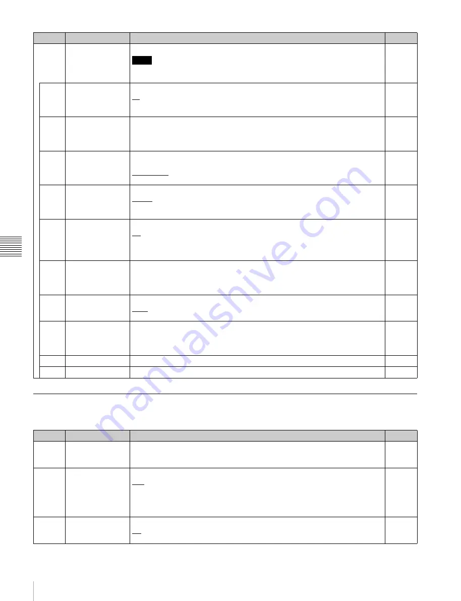
AUDIO Menu

The AUDIO menu allows you to adjust audio signals.

ALT/

[F10]

PORT 
CONFIG

Sets the input/output signals of the input/output ports.

Note

For details on how to switch the signal format of the output ports, see “Switching the 
Signal Format (HD/SD) of the Output Ports”
 in the Appendix.

I/O

[F1]


MULTIPLE

Sets double speed input.

x1:

 Input speed × 1

x2:

 Input speed × 2

When x2 is selected, no audio will be recorded on the audio track.

In

[F2]


SCAN

Sets the scanning method.

Interlace


PsF


Progresv


I/O (HD 
only)

[F3]


SIZE

Sets the resolution.

1280 : 720


1920 : 1080


2048 : 1080


I/O (HD 
only)

[F4]


SIGNAL

Sets the sampling rate of video signals.

YPbPr


RGB


XYZ


I/O (HD 
only)

[F5]


2D/3D

Sets 2D/3D operation.

2D


3D


When 3D is selected for an output port that is set to SD signal output, the video 
signals output from OUT1 and OUT2 will be the same as the monitor output.

I/O

[F6]


SDI

Sets the format of SDI signals.

HDSDI:

 1.5G SDI

3GSDI(A):

 3G SDI Level A

3GSDI(B):

 3G SDI Level B

I/O (HD 
only)

[F7]


DEPTH

Sets the bit length of input/output signals.

10bit


12bit


I/O (HD 
only)

[F8]


COMPRS

Sets the compression mode.

SR-Lite


SR-SQ


SR-HQ


In

[F9]

 SET

Applies 

the 

settings.

I/O

[F10]


EXIT

Redisplays the previous menu.

Button

Indication

Setting

Target

Button

Indication

Setting

Target

[F1]

 AUD 

IN

(ch1 to 16)

Selects the input signal for each audio channel. 

(see page 48)

SDI:

 Selects the signal input to the HD SDI INPUT A connector.

A/E:

 Selects the signal input to the DIGITAL AUDIO INPUT (AES/EBU) connector.

In

[F2]


METER

Switches the display range of the audio level meters between FULL and FINE.

Full:

 The audio level meter display is from –60 dB to 0 dB, or –40 dB to +20 dB. Use 

the ALT/

[F10]

 – 

[F1]

 (SCALE) menu item to set which range (peak level: 0 dB or 

+20 dB) to display.

Fine:

 The audio level meter display range is expanded, and the signal level is 

indicated by a scale with 0.25 dB steps.

I/O

[F7]


SHTL AUD

Sets whether to disable the audio signal output during shuttle playback.

PB:

 Turns muting off.

Muting:

 Turns muting on.

Out

Summary of Contents for SRR1000

Page 1: ...MEMORY STORAGE UNIT SR R1000 OPERATION MANUAL English 1st Edition Revised 1 ...

Page 2: ...en spilled or objects have fallen into the apparatus the apparatus has been exposed to rain or moisture does not operate normally or has been dropped To reduce the risk of fire or electric shock do not expose this apparatus to rain or moisture To avoid electrical shock do not open the cabinet Refer servicing to qualified personnel only THIS APPARATUS MUST BE EARTHED CAUTION Danger of explosion if ...

Page 3: ...comply with the limits for a Class A digital device pursuant to Part 15 of the FCC Rules These limits are designed to provide reasonable protection against harmful interference when the equipment is operated in a commercial environment This equipment generates uses and can radiate radio frequency energy and if not installed and used in accordance with the instruction manual may cause harmful inter...

Page 4: ...on d alimentation câble secteur à 3 fils fiche femelle fiche mâle avec des contacts de mise à la terre conformes à la réglementation de sécurité locale applicable 2 Utilisez un cordon d alimentation câble secteur à 3 fils fiche femelle fiche mâle avec des caractéristiques nominales tension ampérage appropriées Pour toute question sur l utilisation du cordon d alimentation fiche femelle fiche mâle ...

Page 5: ...olgen Sie den Anweisungen für diese Buchse WARNUNG 1 Verwenden Sie ein geprüftes Netzkabel 3 adriges Stromkabel einen geprüften Geräteanschluss einen geprüften Stecker mit Schutzkontakten entsprechend den Sicherheitsvorschriften die im betreffenden Land gelten 2 Verwenden Sie ein Netzkabel 3 adriges Stromkabel einen Geräteanschluss einen Stecker mit den geeigneten Anschlusswerten Volt Ampere Wenn ...

Page 6: ...en in Europa Australien und Neuseeland WARNUNG Dies ist eine Einrichtung welche die Funk Entstörung nach Klasse A besitzt Diese Einrichtung kann im Wohnbereich Funkstörungen verursachen in diesem Fall kann vom Betreiber verlangt werden angemessene Maßnahmen durchzuführen und dafür aufzukommen Hinweis zu fehlerhaften Pixeln auf der LCD Anzeige Die LCD Anzeige in diesem Geräts wird mit Hochpräzision...

Page 7: ...ry Storage Unit Connecting External Devices 26 Using the Unit as a Recorder 26 Using the Unit as a Player 26 Reference Signals 27 Reference Signals for Output Video Signals 27 Reference Signal Connections 28 Selecting the Reference Signal for Output 28 Time Code Settings 29 Selecting the Time Data 29 Setting the Time Code Generator 29 Setting the Time Data 29 Time Code Conversion 30 Superimposing ...

Page 8: ...lecting Audio Signals 48 Selecting the Audio Input Signals 48 Selecting the Audio Signals to Monitor 48 Adjusting the Audio Levels 49 Adjusting the Output Video Signal 50 Chapter 5 Menu Items Saving Settings 52 Detailed Menu Description 53 HOME Menu 53 TC Menu 55 VIDEO Menu 57 AUDIO Menu 60 SETUP Menu 62 Appendix FTP File Operations 65 Directory Structure 65 Preparations 65 Making FTP Connections ...

Page 9: ...s not End Normally 71 Error Messages 73 Warning Messages 75 ERROR LOG Menu 79 Switching the Signal Format HD SD of the Output Ports 79 Recording Formats 80 Playback Format Conversions 1 83 Playback Format Conversions 2 86 Specifications 87 MPEG 4 Visual Patent Portfolio License 89 Index 90 ...

Page 10: ...that consist of 2 In 2 Out 1 In 3 Out 3 In 1 Out 4 In 4 Out etc Dual stream support Each port on the unit supports dual stream video which allows each port to handle two streams of video signals This allows you to record and play back a pair of 3D stereoscopic signals or fill key signals with just a single port The unit can also handle RGB 4 4 4 3D video with a single port 4 channel simultaneous r...

Page 11: ... bits 48 kHz is supported FTP protocol is supported for video data transfer in MXF format via a network Equipped with two network ports that support Gigabit Ethernet Compatible with Sony VTR protocol Sony Disk protocol etc and switcher and controller operations are supported ...

Page 12: ...he control panel consists of the following sections A SRMemory slot section see page 13 B Menu control section see page 14 C Port control section see page 15 G Search control section see page 16 F Recording playback control section see page 15 E Editing control section see page 15 D Numeric buttons see page 15 ...

Page 13: ...ttings for files is being written Flashing purple light1 Files are being deleted or formatting is being performed from the maintenance menu Flashing red light1 Salvaging or formatting is being performed in response to an error Fast flashing red light1 A problem was detected while processing the SRMemory card Eject or salvage the card or perform the appropriate operation as instructed by the messag...

Page 14: ...a function displayed on the menu screen g ALT alternative button Changes the menu screen display h DIAG diagnostic button Displays the maintenance menu when pressed together with the SFT button i MEM button Currently cannot be used j Memory selection buttons M1 to M4 page 41 Select the SRMemory card to use Note on faulty pixels on the LCD panel The LCD panel fitted to this unit is manufactured wit...

Page 15: ...ress to finalize input data E Editing control section Currently cannot be used F Recording playback control section a PREV button Press to display the image of the first frame in the current file Press again to jump to the first frame in the previous file Press this button and the SFT button simultaneously to display the image of the first frame in the file at the top of the file list b NEXT butto...

Page 16: ...ess to enable noiseless playback in the range of 1 to 1 times normal playback speed The button lights when pressed Playback exceeding this speed range is not possible d Search dial Rotate clockwise for forward playback and counterclockwise for reverse playback Shuttle mode Enables playback at the speed corresponding to the position rotation angle of the search dial 100 to 100 times normal playback...

Page 17: ...y will output according to ALT F8 MONITOR SETTING in the VIDEO menu when the input signal is a 3D signal dual stream They will output in 3G when the input signal is 1 5G Dual Link 4 4 4 or 4 2 2 1080P Audio and TC are not superimposed A signal is not output for double speed input c TIME CODE IN connector Inputs a time code generated by an external device d TIME CODE OUT connector When the time cod...

Page 18: ...video signals for the four side by side screens are output The screens are arranged as follows port A top left port B top right port C bottom left port D bottom right The signal format is 4 2 2 1920 1080 and either 59i 50i 24PsF or 23 98PsF Audio is not output c TIME CODE OUT connector Outputs the playback time code d DIGITAL AUDIO OUTPUT AES EBU connector Output the audio signals in AES EBU forma...

Page 19: ... connector Follow the instructions for this port When you connect the network cable of the unit to peripheral device use a shielded type cable to prevent malfunction due to radiation noise C Analog output power supply section a AUDIO MONITOR OUTPUT connectors Outputs the audio monitor signal of input output ports selected with the PORT SELECT button b Main power switch Turns on off the main power ...

Page 20: ...y screen that shows only the selected port When the screen is four port display pressing the PORT SELECT button of the selected port switches to one port display When the screen is a one port display pressing the PORT SELECT button of the selected port redisplays the four port display Main Screen Four port display A Port information display section see page 21 a Menu display section B Status bar s...

Page 21: ... in the one port display screen A Port information display section Four port display b Audio level meters a Menu display section BStatus bar see page 22 APort information display section see page 21 d Video format e Playback recording mark f Remaining time display b SRMemory slot name a Port name c File name g Playback speed display bar h Preview display area i Time data type j LTC VITC k DF NDF l...

Page 22: ... Time Data page 29 j LTC VITC Indicates the time code type LTC or VITC k DF NDF Indicates the drop frame mode l F1 F2 Indicates the field number m Time code Indicates the time code based on the setting of the TC menu n Time code Second area Indicates the time code when the ALT F5 TC2 SEL buttons are set to anything other than Off in the TC menu This is only displayed in the one port display screen...

Page 23: ...sion g Remote control Indicates an input output port that can be manipulated by a remote controller Video Display The video display appears when the display button page 14 is pressed in the port display screen The original screen is redisplayed when the display button is pressed again When the main screen is switched to the video display from the four port display the screen is split into four and...

Page 24: ...yed when not recording or playing f Format information on video being recorded played See the description given in Main Screen page 20 for details on each display You can switch to the video displays of other ports and switch between the one port and four port displays when pressing the PORT SELECT button while the video display is displayed a Port name b SRMemory slot name c Recording playback ma...

Page 25: ...e following information File name Date created Duration Access status the port accessing a file f Detailed file information Displays detailed information on files selected in the file list The following information is displayed Start time code Duration Video format Audio format File list screen displayed when the output port is selected Files recorded in a video format differing to the output port...

Page 26: ...ected to ports A and C and output boards to ports B and D Using the Unit as a Recorder The following shows an example of connecting an HD digital player and other devices to the input ports in order to use the unit as a recorder Using the Unit as a Player The following shows an example of connecting an HD digital recorder and other devices to the output ports in order to use the unit as a player H...

Page 27: ... depending on the unit s operation state settings and input signals Start What is the setting of the HOME menu item F3 REF SEL Is a signal of the correct frequency being input via the REF INPUT connector Is a signal being input via an HD SDI INPUT connector Synchronize with the reference video signal input of the REF INPUT connector Synchronize with the video signal input of an HD SDI INPUT connec...

Page 28: ...the 720 59 94P system is selected EXT HD 1080 59 94i tri level SYNC signal EXT SD 525 black burst signal When the 720 50P system is selected EXT HD 1080 50i tri level SYNC signal EXT SD 625 black burst signal Selecting the Reference Signal for Output Press the F3 REF SEL button in the HOME menu to select the signal to be the reference for operation of the unit Ext Uses the external reference signa...

Page 29: ...codes SDI LTC Synchronizes to the LTC time data of the video signal of the HD SDI INPUT A connector and regenerates the time codes SDI VITC Synchronizes to the VITC time data of the video signal of the HD SDI INPUT A connector and regenerates the time codes Selecting the signal to regenerate Select the signal to regenerate with the F2 REGENE button in the TC menu TC UB Regenerates both the time co...

Page 30: ...he internal time code generator is reset and the time data display becomes 00 00 00 00 for TC or 00 00 00 00 for UB The values read by the time code reader cannot be reset Time data cannot be reset when the internal time code generator is locked to external time codes or to values read by the time code reader To set the user bits 1 Use the F5 TM SEL button in the TC menu to select UB 2 Use the F8 ...

Page 31: ... conversion The time code of the file being played is displayed when the time code is not converted The following table demonstrates the discontinuity of a 25 frame time code when the running frequency is 25 frames the playback file is 24 frames and the Starting TC is set to 01 00 00 00 and the 24F Jumping TC to 22 00 00 00 JUMP TC 3H To preset the Starting TC with numeric buttons Press the F1 STA...

Page 32: ...tons to On in the TC menu Character information is superimposed on signals output from the SD HD SDI MONITOR connector Contents of superimposed data The example above shows the factory set contents of data If you change the setting of the ALT F7 F3 INFO SEL buttons in the TC menu a different type of time data can also be displayed on the second line a Types of time data Note Indication Meaning TCR...

Page 33: ...he file name The file name is displayed in the line following the time data operation mode when the ALT F7 F5 SUB STAT key in the TC menu is set to File The storage information is displayed by the first two characters The above example is SLOT M2 The third character is a colon The fourth to sixteenth characters display the file name If the file name exceeds 13 characters the thirteenth character i...

Page 34: ...to the preset position by pressing the center cursor button Switching to a menu screen other than the TC menu screen ends the setting Handling SRMemory Cards Recommended SRMemory Cards The SRMemory cards supported by the unit and their approximate maximum recording times are as follows For 59 94i Unit minutes approx For 50i Unit minutes approx For 23 98PsF Unit minutes approx The maximum recording...

Page 35: ...ee Combinations of cards that were formatted in different sets cannot be used together SR 512S25 S55 512 GB and SR 1TS25 S55 1 TB SRMemory cards can be used SR 256S15 S55 256 GB cards cannot be used as a virtual volume Changing the operation mode of the unit 1 Remove any cards from slots M2 M3 and M4 2 Press the ALT F7 VIRTUAL buttons in the SETUP menu and change the setting Off Standard operation...

Page 36: ...ion message for formatting appears select OK When formatting completes properly the card will be ready for use as a standard SRMemory card If you format any one of the three cards that compose a virtual volume the remaining two cards must also be reformatted to enable use The formatting procedure will delete all stored data Using a virtual volume on the unit 1 Set the unit to the virtual volume op...

Page 37: ...dard SRMemory card the remaining two cards that compose the virtual volume must also be reformatted to enable use WARNING E40100 to WARNING E40500 VIRTUAL VOLUME WRONG POSITION This warning message appears when the SRMemory cards that compose the virtual volume are inserted in the wrong slots Switch the cards inserted in slots M2 M3 and M4 as instructed by the message to enable use of the virtual ...

Page 38: ...output ports P File Synchronizes two input ports and two output ports For details on specifications see the next section If the ports described in the following section do not exist on your unit this setting cannot be changed Sync mode specifications The specifications for the Port and P File sync modes are as follows Note ALT F1 SYNC selection in the HOME menu Port P File Synchronized ports Synch...

Page 39: ...hanges the format for the other port automatically ALT F1 SYNC selection in the HOME menu Port P File PREV button operations Playback position in middle of file Synchronized Jumps to the start of that file Playback position at start of file Not synchronized Switches to playback of the preceding file in the file list for the selected port Same as during normal operation No change in the port that i...

Page 40: ...tion as SYNC Files However if the files are replicated via FTP transfer receiving or other methods the sync property will not be retained In such cases the files can still be opened as standard files Delete and copy operations performed on individual SYNC Files are not synchronized The operations must be performed on each file Four port display on LCD screen The selected port appears in an orange ...

Page 41: ...nding port in the four port display screen to indicate it is selected 2 Specify the SRMemory slot Press any of the M1 to M4 buttons to specify the SRMemory slot 3 Perform a recording or playback operation When recording to an SRMemory card from an input port and when playing back data from an SRMemory card to an output port select the port first and then the SRMemory slot Association between input...

Page 42: ... in the port A area in the screen Also the indicator below the PORT SELECT button and the indicator for the SRMemory slot are lit red If the SRMemory card is played back at the same time the indicator turns amber 5 Press the STOP button when you want to stop recording Press the STOP button while holding down the SFT button in the numeric keypad when F2 F4 STOP REC in the SETUP menu is set to w shi...

Page 43: ...tion describes the example of recording signals from port A to slot M1 and playing back the same file using port B during recording 1 Select port B with the corresponding PORT SELECT button during recording from port A to M1 2 Select M1 with the corresponding memory selection button A list of files in M1 appears in the screen 3 Use the cursor buttons or MULTI CONTROL knob to select the file being ...

Page 44: ...hieve the desired playback speed The data is played back at a speed that corresponds to the position of the search dial The dial clicks at the positions for 10 0 and 10 times normal playback speed 3 Return the search dial to the center position or press the STOP button to stop shuttle mode playback To return to normal speed playback Press the PLAY button Variable mode playback Follow the procedure...

Page 45: ... the end A mark showing the List status is displayed in the control panel s output port display When menu is set to List Rpt Repeatedly plays playable files displayed in the file list screen Switches to the top of the file list when the last file in the file list is played until the end Switches to the last file from the first file when played in the opposite direction Marks showing the List statu...

Page 46: ...eted To delete all files in the SRMemory card press the ALT F10 ALL DEL buttons Locked files cannot be deleted Copying a file 1 Use the cursor buttons or MULTI CONTROL knob to select the file 2 Press the F5 COPY button Button Indication Description F1 ITEM Selects any of the following items as a sort key for sorting the files Name Cre Date creation date and time Mod Date modification date and time...

Page 47: ...r copied The copying operation will stop when the remaining capacity on the destination SRMemory card becomes insufficient Therefore all the files for which the check box is selected may not be copied in some cases Locking files or SRMemory cards To lock a file You can lock files to prevent them from being edited or deleted Locking a file disables the deleting operations and setting flags Formatti...

Page 48: ...meters on the color display and confirm that the mode is not level setting mode state in which the audio level meters are displayed highlighted in orange The channels for which the signals are currently being monitored are indicated with the reverse video characters L and R below the audio level meters 3 Press F5 MON L button or F6 MON R button in the HOME menu and then use the channel selection b...

Page 49: ...the preset value The input output gain multiplies by 1 0db At that time the digital reference level audio will become the analog reference level audio signal and output from the AUDIO MONITOR OUTPUT connectors When manually adjusting the input level determine a level so that the level meter indicates a level close to the digital reference level when at average volume When manually adjusting the ou...

Page 50: ...erical value 0 0 0H to 141 3 5A70H Adjustable range to 3 dB Adjusting the setup level Use the F5 SETUP button in the VIDEO menu to set the level prst 0 0 Numerical value 10 0 to 10 0 Adjustable range 10 to 10 Adjusting the black output level Use the F6 BLK LV button in the VIDEO menu to set the level prst 0 0 110H Numerical value 31 0 0H to 31 0 220H Adjustable range 31 0 to 31 0 Adjusting the chr...

Page 51: ...a separate screen containing separate menu items for function buttons F1 to F10 Some menus also have submenus Select a submenu to open a submenu screen submenus are registered in the function menu The menu items include operations and settings for the overall unit and settings for each port To access menu items for each port press a Port Select button to select a port and then select a menu For ex...

Page 52: ...nks 1 Press the SETUP button 2 Press the F1 USER BANK button 3 Press one of the following buttons depending on the settings you want to save Overall unit settings F4 SYSTEM SAVE button Output port settings F5 PB PORT SAVE button Input port settings F6 REC PORT SAVE button 4 Press one of the F1 BANK1 to F8 BANK8 buttons to select the bank in which to store Recalling settings from the user banks 1 P...

Page 53: ...tput from the MONITOR OUTPUT L connector see page 48 After pressing the button use the channel selection buttons to select channels 1 to 16 I O F6 MON R Selects the audio channel output from the MONITOR OUTPUT R connector see page 48 After pressing the button use the channel selection buttons to select channels 1 to 16 I O F8 9PIN Turn this On to enable the unit to be controlled from a device conn...

Page 54: ...te 9P connector VTR Disk Sony VTR protocol and Sony Disk protocol VDCP VDCP protocol Odetics Odetics protocol Unit F1 9PIN 1 Sets REMOTE 9P 1 protocol Unit F2 9PIN 2 Sets REMOTE 9P 2 protocol Unit F3 9PIN 3 Sets REMOTE 9P 3 protocol Unit F4 9PIN 4 Sets REMOTE 9P 4 protocol Unit F10 EXIT Returns to the original menu F3 REMOTE FILELIST Selects return information for file information sense commands m...

Page 55: ...s This setting is only enabled when the frame frequency of the unit is 29 97 Hz or 59 94 Hz This setting is only valid when F1 TCG SRC is set to preset I O F5 TM SEL Selects the time data to display on the display To switch between VITC and LTC press the F10 TCR SEL button see page 29 TC UB TM1 TM2 I O F7 TM RESET Resets the time counter I O F8 TM SET Inputs time data see page 29 I O F9 TM HOLD Th...

Page 56: ...C value read by the time code reader before conversion I O ALT F7 CHAR SET Sets the time code and other character information to superimpose on the signal output from the SD HD SDI MONITOR connector see page 32 I O F1 POSITION Allows you to set the display position of character information with the cursor buttons I O F2 SIZE Sets the display size of character information Small Medium I O F3 INFO S...

Page 57: ...D HD SDI OUT connectors see page 50 0 0 to 100 4000H to 141 3 5A70H Out F2 Y Adjusts the Y level of the HD video signal output via the SD HD SDI OUT connectors see page 50 0 0 to 100 4000H to 141 3 5A70H Out F3 PB Adjusts the Pb level of the HD video signal output via the SD HD SDI OUT connectors see page 50 0 0 to 100 4000H to 141 3 5A70H Out F4 PR Adjusts the Pr level of the HD video signal outp...

Page 58: ...BAR PULSR BAR RAMP RAMP Black Black In ALT F1 OUT BLNK Turns on or off vertical interval blanking processing of the HD video signals output via the SD HD SDI OUT connectors Through Does not perform blanking processing Blank Performs blanking processing Out ALT F3 YADD Sets whether to forcibly turn off Y add Auto Off Out ALT F5 A B DISP Sets whether to display the video for the left or right when d...

Page 59: ...s it to left screen and reduces the width of the LINK B signal by half and outputs it to the right half SxS BA Splits the screen into two and then reduces the width of the LINK B signal by half and outputs it to left screen and reduces the width of the LINK A signal by half and outputs it to the right half I O F2 BORDER Selects whether to display a dividing line on the screen when the unit is set ...

Page 60: ...ts the format of SDI signals HDSDI 1 5G SDI 3GSDI A 3G SDI Level A 3GSDI B 3G SDI Level B I O HD only F7 DEPTH Sets the bit length of input output signals 10bit 12bit I O HD only F8 COMPRS Sets the compression mode SR Lite SR SQ SR HQ In F9 SET Applies the settings I O F10 EXIT Redisplays the previous menu Button Indication Setting Target Button Indication Setting Target F1 AUD IN ch1 to 16 Select...

Page 61: ...EBU format audio output assigned to channels 1 to 16 and playback track ch1 to ch16 Out ALT F5 A E IN Selects whether to pass the signals input to the DIGITAL AUDIO INPUT AES EBU connector through the sampling rate converter Auto Passes the input signals through the sampling rate converter In this case there are no limitations on input signals Vlock Does not pass the input signals through the samp...

Page 62: ...nit F4 STOP REC Selects method to stop recording from the control panel Simple Stops recording when the STOP button is pressed w Shift Stops recording when the STOP button is pressed while holding down the SFT button in the numeric keypad Unit F7 DISPLAY SETTING Sets the settings for the display Unit F1 DIMMER Adjusts the brightness of the display backlight Level 1 to Level 3 to Level 5 Unit F3 WA...

Page 63: ...nit F1 MODE Selects the video signal to be output LCD Outputs video signal same as the color display in the control panel Quad Splits the screen into four and outputs video signals that are fitted into the monitors of each port respectively See page 23 for screen configuration details Unit F2 PORT SEL Selects whether to display in the Quad screen an orange colored frame which indicates the selecte...

Page 64: ...Pressing the button performs the freeze operation and pressing the button again cancels the freeze operation Unit ALT F4 ALPHA LV Sets the output level of ALPHA CHANNEL of LINK B output for during 4 4 4 DUAL LINK output White Outputs the white level Black Outputs the black level Unit ALT F6 NAMING Specifies the file naming rule used during recording Seq Generates file names using sequential number...

Page 65: ...ows Vista 1 Open Network and Sharing Center Manage network connections Local Area Connection in the control panel 2 In the Local Area Connection Properties uncheck the Internet Protocol Version 6 TCP IPv6 and then click the OK button Windows 7 1 Open View network status and tasks Change adapter settings Local Area Connection in the control panel 2 In the Local Area Connection Properties uncheck th...

Page 66: ...ssing the space bar and CRLF means a new line entered by pressing the Enter key USER Verifies the user name Command syntax USER SP user name CRLF Input example USER usr1 PASS Verifies the password Command syntax PASS SP password CRLF Input example PASS sr r1000 QUIT Terminates the FTP connection If a file is being transferred terminates after completion of the transfer Command syntax QUIT CRLF POR...

Page 67: ...pecification A list of the file names only in the current directory Input example NLST SRMemoryCard1 RETR Begins transfer of a copy of a file in the specified path on this unit to the current directory on the remote computer Command syntax RETR SP path name CRLF Input example RETR FILE00000010 MXF STOR Copies the MXF files on the computer to the current directory This cannot be used on the network...

Page 68: ...NOOP CRLF PWD Displays the current directory if the directory is the root directory Command syntax PWD CRLF CWD Changes the current directory moves from the current directory to another directory Command syntax CWD SP path name CRLF Moves to a directory as follows depending on whether a directory is specified with path name Directory specified To the specified directory No specification To the roo...

Page 69: ...rameter button of the setting you want to change F1 NETWORK1 IP ADRS IP address of Network 1 F2 NETWORK1 SUBNET Subnet mask of Network 1 F3 NETWORK2 IP ADRS IP address of Network 2 F4 NETWORK2 SUBNET Subnet mask of Network 2 F5 NET1 2 GATEWAY Default gateway of Networks 1 and 2 F6 10G NETWORK IP ADRS IP address of optional 10Gbit network F7 10G NETWORK SUBNET Subnet mask of optional 10Gbit network...

Page 70: ...of the SRMemory cards in the unit for both recording and playback In the above example the input signals from port A B and C on SR SQ 3D mode can be simultaneously recorded to one SRMemory card When both S25 S15 and S55 cards are used Using S25 or S15 cards for recording When one or more S25 or S15 cards are used some limitations to recording and playback apply The following table indicates the nu...

Page 71: ...minutes depending on the state of the SRMemory card when the recording was interrupted Before turning off the main power switch on the connector panel switch the unit to the standby state with the On Standby button on the front panel The salvage function is designed to salvage as much recorded material as possible in the event that an unforeseen accident occurs but there is no guarantee that 100 o...

Page 72: ...ther SRMemory cards that may be inserted During the salvage process the SRMemory card being processed and all other cards in the unit cannot be used In case files cannot be restored with salvage process If the SRMemory card cannot be restored even by performing a salvage formatting the SRMemory card will enable you to use it again 1 Insert the SRMemory card which the salvage did not end normally i...

Page 73: ...c An error was detected at the device initialization stage For details see the Maintenance Manual B80300 SYS1 NW NO COMMUNICATION ERROR A communication error occurred between CPU SYS1 of the SY 422 board and CPU NW of the CPU 453 board B9zz00 CP SYS1 NO COMMUNICATION ERROR etc CP CPU has detected a communication error between CPUs SYS1 CP KP For details see the Maintenance Manual D101pp PORT x ENC...

Page 74: ...matted Format the SRMemory card by following the instructions in the error display screen or remove the card E101pp PORT x COND3 BAD STOP REC Recording was stopped because all the space for replacing bad sectors is consumed on the SRMemory card inserted in the indicated port E106pp PORT x FS STUFFED STOP REC Stopped recording because the SRMemory card used in the displayed port has reached its fil...

Page 75: ...r 0801pp PORT x NO SDI A INPUT P x NO SDI A Signal input to the HD SDI INPUT A connector at the indicated port cannot be detected 0802pp PORT x NO SDI B INPUT P x NO SDI B Signal input to the HD SDI INPUT B connector at the indicated port cannot be detected This message appears only for a signal format that uses the HD SDI INPUT B connector 1901pp PORT x NO A1 A2 INPUT P x NO A1 A2 No carrier dete...

Page 76: ...INFO Since there is no 30 frames sec reference data for the 720 59 94P HD SDI signal input to the indicated port the signal cannot be properly locked 7401pp PORT x ASYNCHRONOUS VIDEO INPUT P x ASYNC VIN The HD SDI input signal at the indicated port is out of phase by 5H or more from the reference signal E101ss SLOT Mx FULL NOT RECORDABLE Mx FULL Because SRMemory card in the indicated slot has no s...

Page 77: ...1100 VIRTUAL VOLUME MOUNT FAILURE M4 is other group of virtual volume Failed to mount the virtual volume The card in slot M4 belongs to a different virtual volume E41200 VIRTUAL VOLUME MOUNT FAILURE M3 is other group of virtual volume Failed to mount the virtual volume The card in slot M3 belongs to a different virtual volume E41300 VIRTUAL VOLUME MOUNT FAILURE M2 is other group of virtual volume ...

Page 78: ... in a dialog box 4 Align the cursor with the setting you want to change and press the center cursor key The line is highlighted in orange when a cursor is aligned with it Code 1 Indication Meaning C101ss SLOT Mx CONDITION1 DOUBTFUL Mx COND1 DBT Errors increase when writing to reading from the SRMemory card in the indicated slot Although all errors are corrected you are recommended to replace the S...

Page 79: ...key In the second line a Searching Now message is displayed blinking in orange while the screen is updating To close the ERROR LOG menu When MAINTENANCE INFORMATION is displayed after pressing the F10 EXIT key several times press a menu selection key such as the HOME button See the Maintenance Menu for details about the ERROR LOG menu Switching the Signal Format HD SD of the Output Ports 1 Turn on...

Page 80: ...94 119i 2D 1 5G 3G 440 PsF 23 98 2D 1 5G 220 x1 3D 1 5G 3G 440 24 2D 1 5G 220 3D 1 5G 3G 440 25 2D 1 5G 220 3D 1 5G 3G 440 29 97 2D 1 5G 220 3D 1 5G 3G 440 Progressive 50 2D 1 5G 3G 440 3D 3G Dual 880 59 94 2D 1 5G 3G 440 3D 3G Dual 880 YPbPr 4 2 2 1280 720 10 Progressive 50 2D 1 5G 220 x1 3D 1 5G 3G 440 59 94 2D 1 5G 220 3D 1 5G 3G 440 YPbPr 4 2 2 2048 1080 10 Progressive 50 2D 1 5G 3G 440 x1 3D ...

Page 81: ...gressive 50 2D 1 5G 440 x1 3D 1 5G 3G 880 59 94 2D 1 5G 440 3D 1 5G 3G 880 YPbPr 4 2 2 2048 1080 10 Progressive 50 2D 1 5G 3G 880 x1 3D 3G Dual 1760 59 94 2D 1 5G 3G 880 3D 3G Dual 1760 RGB 4 4 4 1920 1080 10 Interlace 25 2D 1 5G 3G 440 x1 3D 3G Dual 880 29 97 2D 1 5G 3G 440 3D 3G Dual 880 PsF 23 98 2D 1 5G 3G 440 3D 3G Dual 880 24 2D 1 5G 3G 440 3D 3G Dual 880 25 2D 1 5G 3G 440 3D 3G Dual 880 29 ...

Page 82: ...2D 1 5G 3G 880 3D 3G Dual 1760 29 97 2D 1 5G 3G 880 3D 3G Dual 1760 RGB 4 4 4 1920 1080 12 Interlace 25 2D 1 5G 3G 880 x1 3D 3G Dual 1760 29 97 2D 1 5G 3G 880 3D 3G Dual 1760 PsF 23 98 2D 1 5G 3G 880 3D 3G Dual 1760 24 2D 1 5G 3G 880 3D 3G Dual 1760 25 2D 1 5G 3G 880 3D 3G Dual 1760 29 97 2D 1 5G 3G 880 3D 3G Dual 1760 RGB 4 4 4 2048 1080 10 PsF 23 98 2D 1 5G 3G 880 x1 3D 3G Dual 1760 24 2D 1 5G 3...

Page 83: ...8 2D x1 U U U U U U U U U U U U U U 3D U U U U U U U U U U U U U U 24 2D U U U U U U U U U U U U U U 3D U U U U U U U U U U U U U U 25 2D U U U U U U U U U U U U U U 3D U U U U U U U U U U U U U U 29 97 2D U U U U U U U U U U U U U U 3D U U U U U U U U U U U U U U Progressive 50 2D x1 U U U U U U U U 3D U U U U U U U U 59 94 2D U U U U U U U U 3D U U U U U U U U Conversion support explanation U Ou...

Page 84: ...U U U U U U U U U 29 97 2D U U U U U U U U U U U U U U 3D U U U U U U U U U U U U U U RGB 4 4 4 1920 1080 12 Interlace 25 2D x1 U U U U U U 3D U U U U U U 29 97 2D U U U U U U 3D U U U U U U PsF 23 98 2D x1 U U U U U U U U U U U U U U 3D U U U U U U U U U U U U U U 24 2D U U U U U U U U U U U U U U 3D U U U U U U U U U U U U U U 25 2D U U U U U U U U U U U U U U 3D U U U U U U U U U U U U U U 29 9...

Page 85: ...4 25 29 97 25 29 97 23 98 24 25 29 97 50 59 94 YPbPr 4 2 2 1920 1080 10 Progressive 50 2D x1 U U 3D U U 59 94 2D U U 3D U U Conversion support explanation U Outputs after format conversion U Converts and outputs 3D files as 2D files Outputs the video signal that corresponds to the A connector during HD as SD according to the ALT F8 MONITOR SETTING F1 DUAL setting in the VIDEO menu Outputs in a dif...

Page 86: ...e PsF PsF SIGNAL SIZE DEPTH SCAN Frame 2D 3D MULTIPLE 50 59 94 23 98 24 25 23 98 24 25 YPbPr 4 2 2 1280 720 10 Progressive 50 2D x1 3D 59 94 2D 3D RGB 4 4 4 2048 1080 10 PsF 23 98 2D x1 3D 24 2D 3D 25 2D 3D XYZ 4 4 4 2048 1080 12 PsF 23 98 2D x1 3D 24 2D 3D 25 2D 3D Conversion support explanation Outputs in a different frame frequency Outputs in the same format as during recording ...

Page 87: ...rmat Sampling frequency Y 74 25 MHz Pb Pr 37 125 MHz Quantization 10 bits Compression MPEG4 SStP 444 format Sampling frequency RGB 74 25 MHz Quantization 10 bits 12 bits Compression MPEG4 SStP Audio Digital audio signal format Sampling frequency 48 kHz video sync Quantization 24 bits Headroom 20 dB 18 dB 16 dB 15 dB 12 dB 9 dB selectable Analog monitor output D A quantization 24 bits Input Output ...

Page 88: ...nly available on models with product serial numbers 10001 to 11000 or 50001 to 51000 Analog audio output ANALOG MONITOR OUT XLR male 2 HEADPHONE Phone jack 1 Accessories supplied Operation Guide 1 Installation Manual 1 Operation Manual CD ROM 1 Optional accessories SRK R201 HD Input Board SRK R202 HD Output Board SRMemory cards SR 256S15 S55 256 GB SR 512S25 S55 512 GB SR 1TS25 S55 1 TB Power cord...

Page 89: ...LICENSE IS GRANTED OR SHALL BE IMPLIED FOR ANY OTHER USE ADDITIONAL INFORMATION INCLUDING THAT RELATING TO PROMOTIONAL INTERNAL AND COMMERCIAL USES AND LICENSING MAY BE OBTAINED FROM MPEG LA LLC SEE HTTP WWW MPEGLA COM MPEG LA is offering licenses for i manufacturing sales of any storage media storing MPEG 4 Visual video information ii distribution broadcasting of MPEG 4 Visual video information i...

Page 90: ...r port display 20 FTP file operations 65 Function selection button 14 G GPIO 25 pin connector 19 Ground terminal 19 H HD input board 17 HD SDI INPUT A B connector 17 HD SDI INPUT MONITOR A B MULTI connector 17 HOME menu 53 I In 22 Inhibit button operation 63 Input port 17 Input output port 41 J JOG button 16 Jog mode playback 44 L LEVEL knob 13 Local key map 63 Locking 47 M M1 button 14 Main power...

Page 91: ... SRMemory card 34 SRMemory indicator 13 SRMemory slot 13 41 SRMemory status message 78 Status bar 22 Still picture output 45 STOP button 15 Superimposing 32 Superimposing character information 32 Sync signal 28 System frequency 64 T TC menu 55 Time code 29 Time code generator 29 TIME CODE IN connector 17 TIME CODE OUT connector input board 17 TIME CODE OUT connector output board 18 Time data reset...

Page 92: ... for use by the purchasers of the equipment described in this manual Sony Corporation expressly prohibits the duplication of any portion of this manual or the use thereof for any purpose other than the operation or maintenance of the equipment described in this manual without the express written permission of Sony Corporation ...

Page 93: ...Sony Corporation SR R1000 SY 4 285 471 02 1 2011 ...

Reviews: