background image

Settings

26

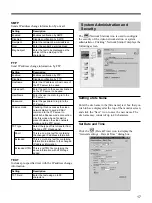
Generic Driver Settings

The 

 (Generic) icon appears when you set the

serial port usage to [Generic]. If it does not appear,
refer to “Serial Port Settings” on page 20, and reset the
serial port usage.

1

Click the “Generic” icon.
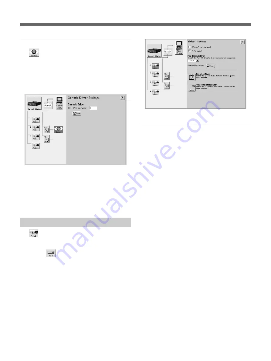
The “Generic Driver Settings” page appears.

2

If you are using a TCP Generic driver through an
Internet browser, type the port number.

3

After you type the port number, click the “Save”
icon.
The settings are saved.

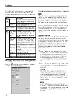
Video Input Setup

The 

 (Video) icons indicate the video sources

connected to the VIDEO 1 to VIDEO 4 input
terminals. If the serial port usage is set for an HSR-1/
1P/2/2P, the 

 (HSR) icon is displayed at the [1]

and [2] video input terminals.
An “

×

” appears to the left of an icon if no video signal

is present at the corresponding input terminal.

This example describes the video input setup
procedure for an EVI-D100/D100P/D30/D31/G20/G21
connected to the S VIDEO input terminal. Set up the
other input terminals similarly.
Clicking the “Video” icon of video input [1] displays
the following screen.

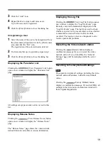
Enabling and Disabling Video Inputs

1

Confirm the [Video 1 is enabled.] box is checked.

z

 Hint

• For optimum performance, we recommend

clearing the checkboxes for any input terminals
that are not being used.

• When unchecked, the input terminal is displayed

as [Disabled].

2

Check the [Y/C input is disabled.] checkbox.

z

 Hint

• When the EVI-D100/D100P/D30/D31/G20/G21

is connected to the VIDEO 1 input terminal, this
setting is off (unchecked).

• This setting is not available for video inputs [2] to

[4].

3

Click the “Save” icon.
The settings are saved.

Summary of Contents for SNT-V304

Page 1: ...Video Network Station 3 204 941 15 1 SNT V304 User s Guide Page 2 Guide de l utilisateur Page 54 GB FR 2000 Sony Corporation ...

Page 2: ... batterij voor memory back up van het geheugen is bevestigd op Z5601 van platt PW 1 Raadpleeg uw leverancier over de verwijdering van de batterij op het moment dat u het apparaat bij einde levensduur afdankt Gooi de batterij niet weg maar lever hem in als KCA Bij dit produkt zijn batterijen geleverd Wanneer deze leeg zijn moet u ze niet weggooien maar inleveren als KCA CAUTION Danger of explosion ...

Page 3: ...ttings 15 System Administration and Security 17 Serial Port Settings 20 Video Input Setup 26 Operation 28 Accessing the Monitor Screen 28 Camera View Operations 29 Pan Tilt Zoom Control 31 Viewing Alarm Event Images 32 HSR View Mode 36 Basic Administration 39 Log File Information 39 Resetting to Factory Defaults 40 Simultaneous Alarm Input to the HSR 1 1P 2 2P and Video Network Station Alarm Memor...

Page 4: ...etwork station can set up and control the HSR 1 1P 2 2P Digital Surveillance Recorders sold separately The video network station can setup and control cameras that support Kalatel protocols Flexible high performance display functions Up to four inputs can be displayed in 2 and 4 division split screens or by sequential switching Very high quality images are made possible by support for Y C signals ...

Page 5: ...xial video cable The video signal format is automatically detected when an NTSC or PAL video source is connected However the VIDEO 1 and S VIDEO terminals cannot both be used at the same time 6 75 Ω Termination Switches The termination resistance of each VIDEO input terminal can be set on or off with these switches When the unit is shipped from the factory all termination switches are ON Note When...

Page 6: ...le 3 COM 2 Terminal 9 Pin D Sub The EVI D100 D100P D30 D31 G20 G21 or a modem can be connected to here The EVI D100 D100P D30 D31 G20 G21 connects using VISCA cable and the modem connects with RS 232C cable 6 5 1 4 3 2 4 ETHERNET 10 100 Terminal RJ 45 Using Category 5 twisted pair cable connect this terminal of the server to the network as a 10 Mbps Ethernet or 100 Mbps Fast Ethernet device 5 I O ...

Page 7: ... VISCA Cable SNT V304 LAN or Internet Modem Ethernet 10 100 Terminal COM2 Terminal RS 232C Cable EVI D30 D31 EVI D30 D31 Video Camera Video Camera VISCA Cable S Video Composite Video Composite Video Composite Video COM1 Terminal S VIDEO Input Terminal VIDEO 2 Input Terminal VIDEO 3 Input Terminal VIDEO 4 Input Terminal EVI D30 D31 Up to 16 devices VISCA Cable COM1 Terminal S VIDEO Input Terminal V...

Page 8: ... terminals of the video network station Note The S VIDEO input terminal and the VIDEO 1 input terminal cannot both be connected at the same time 3 Connect the supplied AC adapter to a power outlet and to the AC IN terminal of the video network station Confirm that the POWER indicator lights steadily IP Address Assignment The video network station must be assigned an IP address to allow access from...

Page 9: ...ing a Web browser on a computer on the network Web Browser Preparation Internet Explorer version 5 0 5 5 or 6 0 must be installed on the computer used to set up the video network station and to view images The SonyCamControl ActiveX component is installed by the following procedure 1 Launch Internet Explorer 2 In the Tools menu select Internet Options click the Security tab set the Security level ...

Page 10: ...nd Application Wizard page 13 has been used to make settings when the server was accessed in the past a monitor screen appears instead of the Welcome page The image of the video camera connected to the VIDEO 1 input terminal is displayed on the Welcome page If no video camera is connected to this terminal NO VIDEO appears instead Data is stored in the cache so that it can be quickly displayed by t...

Page 11: ...an be made without the Wizard In this case click the Admin button on the Welcome page and refer to Accessing the Administration Overview Page on page 12 If the Layout and Application Wizard page 13 has been used to make settings when the server was accessed in the past the Welcome page does not appear In this case click the Admin button on the Welcome page and refer to Accessing the Administration...

Page 12: ...h the same settings at shipping time you should change the password as soon as possible Refer to Changing Passwords and User Registration on page 18 for the procedure A message such as There is no Data may appear when changing the window size from the Administration overview page In this case click the right mouse button and select Refresh Accessing the Administration Overview Page 1 Menu Admin Ov...

Page 13: ...ge is to be initially displayed when the user accesses the monitor screen Camera View Displays the video camera image HSR View Displays the HSR 1 1P 2 2P image Select the image size for the monitor screen from the following Fullsize Display 352 240 NTSC or 352 288 PAL Fullsize 2 Enlarges and displays Fullsize image data in Hugesize 704 480 NTSC or 704 576 PAL Hugesize Display 704 480 NTSC or 704 5...

Page 14: ...ay be entered by separating with commas Up to 100 characters may be entered Enter the title text for the e mail Enter the body text for the e mail Check this box to include in the e mail a link to the real time image on the camera where an alarm event occurs To use Passive mode select this check box Enter the port number Enter the path of the save destination for image files sent by FTP to a host ...

Page 15: ...ects the FTP transfer conditions Enter the host name of the transfer destination Enter the user s name on the host at the transfer destination Enter the password of the above user To use Passive mode select this check box Enter the port number Enter the path of the save destination for image files sent by FTP to a host Enter the file name prefix the fixed part of the file name to be assigned to im...

Page 16: ... BOOTP DHCP Internet Address Default Router Subnet Mask Host Name Bandwidth Control Domain Name Primary DNS Server Secondary DNS Server Primary Mail Server Secondary Mail Server Return Email Address TCP IP Auto mati cally TCP IP manu ally DNS SMTP EMail z Hint BOOTP and DHCP cannot be changed with the Network Wizard BOOTP and DHCP cannot both be enabled at the same time Do not make DNS settings if...

Page 17: ...e text to be displayed as the subject of the email up to 50 characters Setting Enabled Disabled Hostname Upload path User Name Password Passive mode TXT type Short Extended Extended HTML Description Enables notification by FTP Disables notification by FTP Enter the IP address or host name of the FTP server to be used Enter the path to the save destination on the FTP server to be used Enter the use...

Page 18: ... may be up to ten characters long and a password up to eight characters long both consisting of a z A Z and 0 9 2 Place a check in the HSR Control checkbox if the user has permission to control the HSR 1 1P and HSR 2 2P z Hint The CTR button appears in the HSR View to users for whom this box is checked Clicking the CTR button accesses the HSR CONTROL page Refer to HSR View Mode on page 36 for info...

Page 19: ...ation firmware and software version information Displaying the Log File Clicking the View Log File button opens a new window to display the Log file Events page Recently executed commands are displayed on the Log file Events page The log file is used to check whether a special event was executed such as whether a command was issued before or after an alarm occurred The log also serves as a diagnos...

Page 20: ... COM1 is set to HSR or COM2 set to Modem the other option button is not displayed 3 Click the Save icon when finished with the settings The new settings are saved the video network station reboots and the display changes as follows depending on the selected usage When Pan Tilt is selected the Pan Tilt Settings page appears Refer to Pan Tilt Driver and Video Camera ID Setup below When HSR is select...

Page 21: ...eset position for each connected device The following example describes connection of an EVI D100 D100P D30 D31 G20 G21 1 Click the Pan Tilt icon in the Items area The Pan Tilt Settings screen appears 2 Select Sony Visca Driver on the Select driver list z Hint Select Kalatel when connecting devices that support Kalatel protocols Note You cannot change the drivers of ports COM 1 and COM 2 3 Click t...

Page 22: ... 31 for details regarding the functions of the control bar and control buttons 3 Enter a name up to 16 characters for the preset position in the Current position text box z Hint When Kalatel is selected as the pan and tilt driver if you input the preset name as follows you can move the video camera to various preset positions by clicking HOME When HSR 1 1P 2 2P is not connected For Camera1 home1 F...

Page 23: ... setting To apply changed settings the SET button must be clicked on each page Changes to settings will not be saved unless you click the SET button Display response may slow briefly while settings are being saved Some display slow down is normal while settings are being stored in the HSR 1 1P 2 2P this does not indicate a problem with the video network station Available settings differ according ...

Page 24: ... video network station can change the passwords for any connected HSR 1 1P 2 2P The system manager s password should therefore be handled carefully Setting and Canceling HSR 1 1P 2 2P Passwords The password entered for PASSWORD SETTING on the FUNCTION CONTROL page may consist of up to four characters Asterisks are displayed when the HSR 1 1P 2 2P password has been set To cancel a password delete t...

Page 25: ...t connecting after detecting a dial tone or select YES to start connecting without a dial tone Select Null if the modem is connected with a null modem crossed cable or Autodetected Modem otherwise Select the communication speed between the serial port and modem Select either Tone Dialing ATDT or Pulse Dialing ATDP according to the type of telephone circuit used for the modem connection Select CTS ...

Page 26: ... appears to the left of an icon if no video signal is present at the corresponding input terminal This example describes the video input setup procedure for an EVI D100 D100P D30 D31 G20 G21 connected to the S VIDEO input terminal Set up the other input terminals similarly Clicking the Video icon of video input 1 displays the following screen Enabling and Disabling Video Inputs 1 Confirm the Video...

Page 27: ...ffset setting is valid only when the image display is Fullsize Verify the monitor screen after changing settings and correct the setting values if the image does not display correctly Setting the Video Input Modulation Method Click the Video Input Modulation icon to display the Input Modulation for Video 1 dialog box If only the current video source is to be set select Video 1 s in the Apply searc...

Page 28: ...ow your user name and password ask your system administrator The monitor screen appears The monitor screen shows either the Camera View or HSR View the above example is the Camera View A system setting determines which is displayed initially Monitoring Precautions Up to eight users can be logged on at the same time If the network bandwidth setting is too slow all images in the four screen display ...

Page 29: ...era View displays the video camera images Use the screen buttons and icons to switch between cameras and display modes 1 ALL Button Clicking this button switches the monitor screen to the ALL mode as shown in the above example In the ALL mode one two or four images from cameras connected to the video network station are displayed 2 CAM1 to CAM4 Buttons Clicking one of these buttons changes the mon...

Page 30: ...ages on page 32 8 RELAY Button Clicking this activates or deactivates the relay output according to the system administrator settings 9 HOME Button Returns the video camera to the home position q PRESET Drop Down List Select a preset camera position by name from this list to set the camera to that fixed position previously set by the system administrator qa HSR Button Clicking this button changes ...

Page 31: ...rt Char3 42h Gate Open OFF Stop Char3 62h AUX 2 Button Gate Open OFF Start Char3 48h Gate Open OFF Stop Char3 68h AUX 3 Button Slow Start Char3 4Ah Slow Stop Char3 6Ah 9 HOME Button Returns the video camera to the home position Pan Tilt Zoom Control When an EVI D100 D100P D30 D31 G20 G21 is connected to a serial port on the video network station camera pan tilt and zoom can be controlled from the ...

Page 32: ...ved during an alarm event The Alarm mode provides an Alarm List screen List display Alarm Replay screen moving image display and an Alarm Thumbnail screen thumbnail display In Alarm mode use the Snapshot icon to view saved images the same way you check Alarm images Alarm Event Actions The following actions are performed when an alarm event occurs The alarm trigger alarm time and images before and ...

Page 33: ... Alarm Event Time Shows the alarm event time 7 Number of Images before alarm Shows the number of images saved before the alarm event 8 Number of Images after alarm Shows the number of images saved after the alarm event 9 Scroll Bar Allows scrolling the list when it is longer than one page The alarm contents saved in memory can be displayed as a list Clicking the ALARM button in the Camera View dis...

Page 34: ...ugesize 4 Movie Control Bar Click the following icons to control play B Play X Pause x Stop Position bar click to choose another play position M Step forward one frame m Step back one frame 5 Thumbnail Display Icon Click to display the Alarm Thumbnail screen 6 Return to Alarm List Icon Click to display the Alarm List screen Alarm events saved in memory can be replayed as a moving image 2 4 3 6 5 1...

Page 35: ...m event date and time 3 Alarm Event Image The image at the moment an alarm event occurred is framed in red 4 Return to Alarm List Icon Click to display the Alarm List screen 5 Page Number Shows the page number 6 Alarm Images Displays the saved alarm images before and after the alarm event as thumbnails Clicking an image switches to the Alarm Replay screen showing that image 7 AR Button Click to di...

Page 36: ...connected EVI D100 D100P D30 D31 G20 G21 If no video camera ID number has been set in the system settings or if an EVI D100 D100P D30 D31 G20 G21 is not connected or is turned off this indicator is colored gray 6 4 5 7 8 9 0 qa qd 3 2 Camera Number Buttons Clicking one of these buttons displays the image from that video camera While monitoring an image the camera number on the button corresponds t...

Page 37: ...on displays the Admin overview page where video network station settings and management can be performed Access to this page is normally restricted to the administrator qa Connection Status Shows the type of HSR unit HSR 1 1P or HSR 2 2P connected to the video network station If the connected HSR 1 1P 2 2P is not turned on or communicating properly DISCONNECT is displayed qs Date and Time This is ...

Page 38: ... X Pause or B Play button drag the slider again 2 ALARM CANCEL Button Clicking this button cancels the alarm input to the HSR 1 1P 2 2P It can be used to cancel the alarm before the cancellation interval set for the HSR 1 1P 2 2P has elapsed 3 X Pause Button Clicking this button during variable speed play with Slider 1 pauses image play 2 1 3 4 5 4 PRE REVERSE PLAY Button This button is enabled wh...

Page 39: ...ts page opens showing portions of the commands recently executed by the video network station Checking the Log File The log file is saved as a text file that can be opened with a text editor The following information is typically found in the log file Fri Apr 30 09 56 35 Info Initialize video decoders Fri Apr 30 09 56 41 Detection of color standard Fri Apr 30 09 56 41 Saa7111Decoder Found PAL BGHI...

Page 40: ...ESET switch is located inside the small hole between the VIDEO 3 and VIDEO 4 input terminals 3 Reconnect the power cable while holding the RESET switch down 4 When the STATUS indicator lights yellow release the RESET switch After about five seconds the video network station reboots The video network station settings are returned to their factory default values Resetting to Factory Defaults from th...

Page 41: ...vents recorded on the HSR 1 1P 2 2P can be easily confirmed on the video network station monitor without using the alarm search function of the HSR 1 1P 2 2P To confirm alarm events precisely using the video network station alarm memory as an index perform an alarm search using the HSR 1 1P 2 2P Connecting the Alarm Device Refer to the HSR 1 1P 2 2P Users Guide for details of alarm device wiring a...

Page 42: ...cording When four video cameras are connected to HSR 1 1P 2 2P video input terminals 1 to 4 and the HSR View is set to display four partitions if an alarm event occurs at any camera the number of images set for the Number of PRE alarm Images is saved However in this case the saved image will consist of the four displayed partitions Setting Value REMORT CONTROL PARALLEL OUTPUT OUT 1 pin 15 ALARM PA...

Page 43: ...ice A problem may be present in the power supply Eight users are already logged onto this unit Only eight users can log onto this unit at any one time Symptom The NETWORK indicator lights red The server operates locally but not beyond the router The image does not refresh even when the Refresh button in the Web browser is pressed or the image refreshes slowly or both Poor image quality Possible Ca...

Page 44: ...the battery is depleted the data and time settings are lost Contact your Sony Service Center to have the battery replaced for a charge Presuming the power is normally kept on If the power is regularly turned off battery life can be expected to be about one year Actual battery life depends on the operating conditions ...

Page 45: ... overlays Network Connection10Base T or 100Base TX Protocols TCP IP HTTP FTP SMTP NTP DNS ICMP ARP BOOTP DHCP Pre and Post Alarm Buffer Up to 4 MB is available to store images before and after alarm events Pan Tilt Zoom PTZ Supports camera control from a remote control Supported devices Sony EVI D100 D100P D30 D31 G20 G21 Supported protocols VISCA Kalatel Security User level password protection Im...

Page 46: ...pler Input 4 Photocoupler RS 485 B RS 485 A Photocoupler power Input 1 Photocoupler Input 1 Photocoupler Input 2 Photocoupler Input 2 Photocoupler Relay Switch Relay Switch Description Do not use Photocoupler input 3 the sash and contacts are electrically isolated so input can be an external DC voltage or DC power input output from pins 9 and 10 Photocoupler input 4 same as Photocoupler input 3 ab...

Page 47: ...llector outputs that do not need to be electrically isolated connect as follows Inside server Outside server Approx 4 7 kΩ Alarm Device 5 to 20V DC Output Max 24V AC DC 100 mA Pins 3 5 11 and 13 Pins 4 6 12 and 14 Pin 15 Pin 16 Inside server Outside server Approx 4 7 kΩ Pins 3 5 11 and 13 Pins 4 6 12 and 14 Pin 9 Pin 10 Mechanically switched output device Mechanically switched output device Note I...

Page 48: ... used for Kalatel Pans the device relative to the current position Tilts the device relative to the current position Moves zoom Positive values means zoom in and negative values means zoom out Only used for Kalatel Moves focus Positive values means focus near and negative values means focus far Only used for Kalatel CGI Generic Driver Commands The following CGI parameter descriptions are intended ...

Page 49: ...r Move to the position associated with the preset name Sets the head speed of the device connected to the specified camera Not used for Kalatel z Controlling and Monitoring Relay 4 digital inputs Method GET POST Syntax input http servername cgi bin io input cgi parameter value parameter value Syntax output http servername cgi bin io output cgi parameter value parameter value with the following par...

Page 50: ...T Syntax control serial port http servername cgi bin control parameter value parameter value with the following parameter and values z TCP Generic driver Set a TCP port number in the Generic driver settings 0 disabled It is now possible for clients to connect to the specified TCP port number The data sent from the connected client is forwarded to the serial port on the video network station and th...

Page 51: ...ail Address 16 Network Station Site Name 17 Date Time 17 Format 18 Synchronize Set 18 Security 18 Password 18 User 18 View Parameter List 19 View Log File 19 View Release Notes 19 Restart 19 Factory Default 19 COM Page RS232 RS485 20 Baud rate 20 Data bits 20 Stop bits 20 Parity 20 Pan Tilt 21 Driver 21 ID 21 Preset Name 22 HSR 22 Setup 23 Maintenance 23 Modem 25 Modem Type 25 Dial Tone 25 Type 25...

Page 52: ... first check for the cause Refer to this operating manual for the possible causes and remedy If the problem persists ask for service Contact your supplier or nearest Sony Customer Service Center Repairs within the warranty period We will provide repairs according to the terms of the warranty card Refer to the warranty card for details Repairs outside of the warranty period If repair is deemed feas...

Page 53: ......

Page 54: ...e du même type ou d un type équivalent recommandé par le constructeur Mettre au rebut les batteries usagées conformément aux instructions du fabricant Le système d exploitation dans la video network station est basé sur Linux 2 0 kernel le code source disponible sous http developer axis com download elinux Microsoft MS DOS Windows Windows NT et ActiveX sont des marques déposées de Microsoft Corpor...

Page 55: ... système et sécurité 70 Réglages du port série 72 Réglage de l entrée vidéo 79 Fonctionnement 82 Accès à l écran moniteur 82 Opérations Camera View 83 Contrôle Panoramique Inclinaison Zoom 85 Visionnement des images en cas d alarme 86 Mode HSR View 90 Administration de base 93 Informations sur le fichier journal 93 Réglages par défaut d usine 94 Entrée simultanée d alarme dans le HSR 1 1P 2 2P et ...

Page 56: ...La video network station peut régler et contrôler les enregistreurs de surveillance numériques HSR 1 1P 2 2P vendus séparément La video network station peut régler et contrôler les caméras qui acceptent les protocoles Kalatel Fonctions d affichage haute performance flexible Il est possible d afficher jusqu à quatre entrées sur des écrans avec 2 ou 4 segmentations ou par commutation séquentielle Il...

Page 57: ...vidéo est automatiquement détecté lorsqu une source vidéo NTSC ou PAL est raccordée Par contre il n est pas possible d utiliser les bornes VIDEO 1 et S VIDEO en même temps 6 Connecteurs de terminaison 75 Ω La résistance de terminaison de chaque borne d entrée VIDEO peut être activée ou désactivée à l aide de ces connecteurs A départ d usine tous les connecteurs de terminaison sont ON Remarque Lors...

Page 58: ...D Sub Les EVI D100 D100P D30 D31 G20 G21 ou un modem peuvent être raccordés ici Le EVI D100 D100P D30 D31 G20 G21 se raccorde à l aide du câble VISCA et le modem à l aide du câble RS 232C 6 5 1 4 3 2 4 Borne ETHERNET 10 100 RJ 45 Raccorder cette borne du serveur à l aide d un câble bifilaire torsadé catégorie 5 au réseau en tant que périphérique 10 Mbps Ethernet ou 100 Mbps Fast Ethernet 5 Connect...

Page 59: ... régler et de le commander à partir d un ordinateur sur le réseau EVI D30 D31 EVI D30 D31 Caméra vidéo Caméra vidéo Câble VISCA Câble VISCA S Video Borne COM1 Borne d entrée S VIDEO Borne d entrée VIDEO 2 Borne d entrée VIDEO 3 Borne d entrée VIDEO 4 SNT V304 LAN ou Internet Modem Borne Ethernet 10 100 Borne COM2 Câble RS 232C Vidéo composite Vidéo composite Vidéo composite EVI D30 D31 Jusqu à 16 ...

Page 60: ...x bornes entrée et sortie de la video network station Remarque Les bornes d entrée S VIDEO et VIDEO 1 ne peuvent pas être raccordées toutes deux en même temps 3 Raccorder l adaptateur AC fourni à une prise murale et à la borne AC IN de la video network station Confirmer que l indicateur POWER reste allumé Attribution de l adresse IP Il faut attribuer une adresse IP à la video network station pour ...

Page 61: ...ateur Web d un ordinateur du réseau Préparatif du navigateur Web Internet Explorer version 5 0 5 5 ou 6 0 doit être installé sur l ordinateur utilisé pour configurer la video network station et pour visionner des images SonyCamControl composant ActiveX est installé selon la procédure suivante 1 Lancer Internet Explorer 2 Dans le menu Outils sélectionner Options Internet cliquer sur l onglet Sécuri...

Page 62: ...a été utilisé pour effectuer des réglages lors d un accès précédent au serveur un écran de moniteur apparaît à la place de la page Welcome L image de la caméra vidéo raccordée à la borne VIDEO 1 est affichée dans la page Welcome Si aucune caméra vidéo n est raccordée à cette borne alors NO VIDEO apparaît à la place Les données sont enregistrées dans le cache pour être rapidement affichées par le n...

Page 63: ...être effectués sans l assistant Cliquer dans ce cas sur le bouton Admin dans la page Welcome et se reporter à Accès à la page Administration Overview en page 64 Si le Layout and Application Wizard page 65 a été utilisé pour effectuer les réglages lors d un précédent accès au serveur la page Welcome n apparaît pas Cliquer dans ce cas sur le bouton Admin dans la page Welcome et se reporter à Accès à...

Page 64: ...usine il faut changer le mot de passe dès que possible Se reporter à Changement des mots de passe et enregistrement de l utilisateur en page 71 pour la procédure Un message tel que Absence de données peut apparaître lors de la modification de la taille de la fenêtre dans la page Administration overview Cliquer dans ce cas sur le bouton droit de la souris et sélectionner Actualiser Accès à la page ...

Page 65: ...électionner l image à afficher initialement lors de l accès de l utilisateur à l écran moniteur Camera View Affiche l image de la caméra vidéo HSR View Affiche l image du HSR 1 1P 2 2P Sélectionner le format de l image pour l écran moniteur parmi Fullsize Affiche 352 240 NTSC ou 352 288 PAL Fullsize 2 Agrandit et affiche des données d image Fullsize en Hugesize 704 480 NTSC ou 704 576 PAL Hugesize...

Page 66: ...r ajouter la date et l heure au nom de fichier de base Sélectionner ce bouton pour ajouter un numéro séquentiel au préfixe En ajoutant un numéro séquentiel au préfixe sélectionner ce bouton et entrer une valeur pour spécifier un maximum pour le numéro Réglage Alarm Buffer Overwrite Alarm Pop Up window Switch an image when Alarm is ON Relay OUT at Alarm Description Une capacité prédéterminée de mém...

Page 67: ...u à l extérieur de l intervalle de Primary Time Enabled Réglages Relay OUT Réglage Secondary Image Frequency Take Pictures Host Name User Name Password Use Passive Mode FTP Port Number Upload Path Base File Name Overwrite Date Time Suffix Sequence Number Suffix set to Maximum Sequence Number Suffix up to Description Permet de régler le transfert de transfert dìmage FTP Sélectionner les secondes le...

Page 68: ... IP du serveur DNS secondaire Le serveur DNS secondaire est utilisé lorsque le serveur DNS primaire n est pas utilisable ou n est pas disponible Entrer l adresse IP ou le nom du serveur e mail primaire Entrer l adresse IP ou le nom du serveur e mail secondaire Le serveur e mail secondaire est utilisé lorsque le serveur e mail primaire n est pas utilisable ou n est pas disponible Entrer l adresse r...

Page 69: ...sse Lors de la connexion à un ordinateur hôte spécifié par l URL via un serveur mandataire entrer l adresse IP de ce dernier Entrer le numéro de port utilisé par le serveur mandataire Si un nom d utilisateur est requis pour la connexion au serveur mandataire entrer le nom d utilisateur Si un mot de passe est requis pour la connexion au serveur mandataire entrer le mot de passe SMTP Envoie les info...

Page 70: ...ra Time New Camera Time Description Sélectionner le format d affichage de la date et de l heure sur l écran moniteur dans la liste déroulante Sélectionner 12h ou 24h pour un affichage de 12 ou de 24 heures Affiche la date et l heure actuelles La date et l heure affichées ne peuvent pas être éditées Activer pour synchroniser l horloge de la video network station avec l horloge interne de l ordinate...

Page 71: ...utilisateur à enregistrer dans le champ User name de l article Add user et entrer leur mot de passe dans les champs User password et Confirm password Un nom d utilisateur peut être de dix caractères maximum et le mot de passe de huit caractères entre a z A Z et 0 9 2 Cocher la case HSR Control si l utilisateur a l autorisation de contrôler les HSR 1 1P et HSR 2 2P z Conseil Le bouton CTR apparaît ...

Page 72: ...Restart pour afficher un message de confirmation pour redémarrer la video network station Si l on clique sur le bouton OK la page General Settings sera affichée de nouveau après le redémarrage du serveur Retour aux réglages par défaut d usine Remarque Cette opération remet tous les réglages y compris l adresse IP de la video network station à leurs valeurs par défaut au départ d usine Cliquer sur ...

Page 73: ... network station à n importe quel moment Par conséquent lorsque COM1 est réglé sur HSR ou COM2 est réglé sur Modem l autre bouton d option n est pas affiché 3 Cliquer sur l icône Save à la fin des réglages Les nouveaux réglages sont enregistrés la video network station redémarre et l affichage change comme suit en fonction de l usage sélectionné Lorsque Pan Tilt est sélectionné la page Pan Tilt Se...

Page 74: ...o ID doit être différent des autres périphériques Lorsque le pilote VISCA est utilisé régler les mêmes numéros que l ordre des connexions dans la chaîne bouclée Lorsqu un HSR 1 1P 2 2P est raccordé à la borne COM1 un numéro ID peut être réglé pour chaque caméra raccordée au HSR 1 1P 2 2P 6 Cliquer sur le bouton Apply Les réglages sont appliqués et l icône Preset Positions est ajoutée à la caméra v...

Page 75: ...cordé à la borne COM1 de la video network station et si l icône HSR n apparaît pas à côté de l icône COM1 réinitialiser l utilisation du port série en se reportant à Réglages du port série en page 72 1 Cliquer sur l icône Preset Positions sur la page pour régler les numéros ID de la caméra vidéo voir page 73 La page Preset Positions apparaît dans la nouvelle fenêtre 2 Observer l image échantillon ...

Page 76: ...r le fait qu à l envoi de la première ligne du nouveau réglage MON 03 00 la seconde ligne du réglage précédent est copiée MON 03 00 et la video network station lit ceci comme une erreur Pour éviter cela effectuer la procédure suivante Cliquer sur l icône HSR pour afficher la page Sony HSR Settings Utiliser l icône SETUP pour effectuer les réglages HSR 1 1P 2 2P dans la page Web Cliquer sur l icône...

Page 77: ...raccordé Le mot de passe du gestionnaire du système doit par conséquent être manipulé avec précaution Réglage et annulation des mots de passe de HSR 1 1P 2 2P Le mot de passe entré pour PASSWORD SETTING dans la page FUNCTION CONTROL peut comporter quatre caractères maximum Des astérisques s affichent à la place du mot de passe du HSR 1 1P 2 2P Pour annuler un mot de passe effacer les astérisques a...

Page 78: ...er NO pour commencer la connexion après avoir détecté la tonalité ou sélectionner YES pour commencer sans la tonalité Sélectionner Null si le modem est raccordé avec un câble croisé modem vide sinon sélectionner Autodetected Modem Sélectionner la vitesse de communication entre le port série et le modem Sélectionner Tone Dialing ATDT ou Pulse Dialing ATDP en fonction du type de circuit téléphonique...

Page 79: ... et 2 Un apparaît à gauche d une icône si aucun signal vidéo n est présent à la borne d entrée correspondante Cet exemple décrit la procédure de réglage de l entrée vidéo pour un EVI D100 D100P D30 D31 G20 G21 raccordé à la borne d entrée S VIDEO Régler de la même manière les autres bornes d entrée Cliquer sur l icône Video de l entrée vidéo 1 pour afficher l écran suivant Activer et désactiver le...

Page 80: ...ments Description Cocher cette case pour afficher la date et l heure avec l image vidéo Cocher cette case pour afficher un texte tel que le titre de la caméra avec l image vidéo Entrer le texte à afficher jusqu à 16 caractères Sélectionner s il faut afficher l image vidéo en couleur ou en monochrome Sélectionner l un des cinq rapports de qualité d image vidéo La qualité d image la plus élevée est ...

Page 81: ...source vidéo pour détecter le type de modulation à attribuer à la source sélectionnée Réglage manuel Sélectionner un type de modulation dans la liste déroulante Camera 1 input et cliquer sur l icône Save pour enregistrer la sélection z Conseil IL existe plusieurs standards de modulation vidéo actuellement utilisés dans diverses régions Le format vidéo NTSC généralement utilisé au Japon et en Améri...

Page 82: ... de passe L écran moniteur apparaît L écran moniteur montre soit Camera View soit HSR View l exemple ci dessus est Camera View Un réglage système détermine celui affiché initialement Précautions de visionnement Il est possible d entrer huit utilisateurs en même temps Si le réglage de la largeur de bande du réseau est trop lent toutes les images de l affichage à quatre écrans du mode ALL de Camera ...

Page 83: ... boutons et icônes de l écran pour commuter entre les modes caméras et affichage 1 Bouton ALL Cliquer sur ce bouton pour passer l écran moniteur sur le mode ALL tel qu indiqué dans l exemple ci dessus Dans le mode ALL une deux ou quatre images des caméras raccordées à la video network station sont affichées 2 Boutons CAM1 à CAM4 Cliquer sur l un de ces boutons pour changer l écran moniteur sur le ...

Page 84: ...affichage en format Fullsize JPEG dans la mémoire de la video network station Pour afficher les images enregistrées de cette manière se reporter à Visionnement des images en cas d alarme en page 86 7 Indicateur de sortie relais Lorsque la sortie relais est active cet indicateur s allume en bleu Lorsqu elle est inactive il s allume en gris 8 Bouton RELAY Cliquer dessus pour activer ou désactiver la...

Page 85: ...3 42h Gate Open OFF Stop Char3 62h Bouton AUX2 Gate Open OFF Start Char3 48h Gate Open OFF Stop Char3 68h Bouton AUX3 Slow Start Char3 4Ah Slow Stop Char3 6Ah 9 Bouton HOME Remet la caméra vidéo sur la position initiale Contrôle Panoramique Inclinaison Zoom Lorsqu un EVI D100 D100P D30 D31 G20 G21 est raccordé à un port série de la video network station la panoramique l inclinaison et le zoom de l...

Page 86: ... donne un écran Alarm List affichage de liste un écran Alarm Replay déplacer l affichage d image et un écran Alarm Thumbnail affichage miniature En mode Alarme utiliser l icône Snapshot pour visionner les images enregistrées de la même manière que la vérification des images en cas d alarme Actions en cas d alarme Les actions suivantes sont effectuées lorsqu une alarme se produit Le déclencheur d a...

Page 87: ... à laquelle l alarme s est produite 7 Nombre d images avant l alarme Montre le nombre d images enregistrées avant le début d une alarme 8 Nombre d images après une alarme Montre le nombre d images enregistrées après une alarme 9 Barre de défilement Permet de dérouler la liste lorsqu elle fait plus d une page Le contenu de l alarme enregistré dans la mémoire peut être affiché comme liste Cliquer su...

Page 88: ...gesize 4 Barre de contrôle de film Cliquer sur les icônes suivantes pour contrôler la lecture B Lecture X Pause x Arrêt Barre de position cliquer pour choisir une autre position de lecture M une image en avant m une image en arrière 5 Icône d affichage de miniature Cliquer pour afficher l écran miniature d alarme 6 Icône de retour à Alarm List Cliquer pour afficher l écran Alarm List Les alarmes e...

Page 89: ...e de l alarme 3 Image d alarme L image du moment où l alarme s est produite est encadrée en rouge 4 Icône de retour à Alarm List Cliquer pour afficher l écran Alarm List 5 Numéro de page Montre le numéro de page 6 Images d alarme Affiche les images d alarme enregistrées avant et après une alarme en miniature Cliquer sur une image pour passer dans l écran Alarm Replay montrant cette image 7 Bouton ...

Page 90: ...que inclinaison zoom est disponible via un EVI D100 D100P D30 D31 G20 G21 raccordé Si aucun numéro ID de caméra vidéo n a été réglé dans les réglages système ou si un EVI D100 D100P D30 D31 G20 G21 n est pas raccordé ou n est pas mis sous tension cet indicateur est de couleur grise 6 4 5 7 8 qa qd 2 Boutons de numéro de caméra Cliquer sur l un des boutons pour afficher l image de la caméra vidéo L...

Page 91: ...ur Camera View 0 Bouton Admin Cliquer sur ce bouton pour afficher la page Admin overview dans laquelle les réglages et la gestion de la video network station peuvent être effectués L accès à cette page est normalement réservé à l administrateur qa Etat de la connexion Montre le type de l unité HSR HSR 1 1P ou HSR 2 2P raccordé à la video network station Si le HSR 1 1P 2 2P raccordé n est pas mis s...

Page 92: ...u point où elle est relâchée après l avoir glissée Pour reprendre la lecture à la nouvelle vitesse après l avoir arrêtée avec le bouton X Pause ou B Lecture glisser de nouveau la réglette 2 Bouton ALARM CANCEL Cliquer sur ce bouton pour annuler l entrée d alarme au HSR 1 1P 2 2P Il peut être utilisé pour annuler l alarme avant la fin de l intervalle d annulation réglé pour le HSR 1 1P 2 2P 2 1 3 4...

Page 93: ...iew Log File La page Log file Events s ouvre montrant des parties des commandes récemment exécutées par la video network station Vérification du fichier journal Le fichier journal est enregistré en tant que fichier texte qui peut être ouvert avec un éditeur de texte Les informations suivantes se trouvent en général dans un fichier journal Fri Apr 30 09 56 35 Info Initialize video decoders Fri Apr ...

Page 94: ...ur RESET se trouve dans la petite fente entre les bornes VIDEO 3 et VIDEO 4 3 Rebrancher le câble d alimentation tout en maintenant le commutateur RESET vers le bas 4 Lorsque l indicateur STATUS s allume en jaune relâcher le commutateur RESET Après cinq secondes environ la video network station redémarre Les réglages de la video network station reviennent à leurs valeurs par défaut d usine Réiniti...

Page 95: ...cilement confirmées sur le moniteur de la video network station sans utiliser la fonction de recherche d alarme du HSR 1 1P 2 2P Pour confirmer précisément les alarmes en utilisant la mémoire d alarme de la video network station comme index effectuer une recherche d alarme à l aide du HSR 1 1P 2 2P Connexion d un périphérique d alarme Se reporter au guide de l utilisateur du HSR 1 1P 2 2P pour les...

Page 96: ...HSR 1 1P 2 2P pour les détails sur l enregistrement d alarme du HSR 1 1P 2 2P Lorsque quatre caméras vidéo sont raccordées aux bornes d entrée vidéo 1 à 4 du HSR 1 1P 2 2P et HSR View est réglé pour afficher quatre partitions et qu une alarme se produit à l une des caméras le nombre d images réglé pour Number of PRE alarm Images est sauvegardé Par contre l image enregistrée constitue les quatre pa...

Page 97: ...appareil Huit utilisateurs seulement peuvent être branchés en même temps à cet appareil Symptôme L indicateur NETWORK s allume en rouge Le serveur fonctionne localement et non au delà du routage L image n est pas restaurée même lorsque le bouton Actualiser est appuyé dans le navigateur Web ou bien l image est restaurée lentement ou bien les deux Mauvaise qualité d image Cause possible Il y a proba...

Page 98: ...blement réduite les réglages de date et heure sont perdus Contacter le service après vente Sony pour remplacer la batterie pour la charge En assumant que l appareil est constamment mis sous tension Si l appareil est régulièrement mis hors tension la durée de vie de la batterie sera d environ un an La durée de vie actuelle de la batterie dépend des conditions d utilisation ...

Page 99: ...u 100Base TX Protocoles TCP IP HTTP FTP SMTP NTP DNS ICMP ARP BOOTP DHCP Pré and Post tampon d alarme jusqu à 4 MB disponibles pour enregistrer les images avant et après une alarme Panoramique Inclinaison Zoom PTZ Accepte le contrôle de caméra à partir d une télécommande Périphériques compatibles Sony EVI D100 D100P D30 D31 G20 G21 Protocoles compatibles VISCA Kalatel Sécurité Protection par mot d...

Page 100: ...85 A Alimentation Photocoupleur Entrée 1 Photocoupleur Entrée 1 Photocoupleur Entrée 2 Photocoupleur Entrée 2 Photocoupleur Commutateur relais Commutateur relais Description Ne pas utiliser Photocoupleur entrée 3 l habillage et les contacts sont électriquement isolés donc l entrée peut être une tension DC externe ou une entrée sortie d alimentation DC à partir des broches 9 et 10 Photocoupleur ent...

Page 101: ...t ne nécessitant pas d isolation électrique raccorder comme suit Remarque Insérer une diode de protection lors de la connexion d une charge conductrice tel qu un relais aux broches de sortie d alarme 15 et 16 Dans le serveur En dehors du serveur Env 4 7 kΩ Broches 3 5 11 et 13 Broches 4 6 12 et 14 Broche 9 Broche 10 Périphérique de sortie raccordé mécaniquement Périphérique de sortie raccordé méca...

Page 102: ... i e lower quality and smaller image size Sets level of color or grayscale 0 grayscale 100 full color Shows hides the time stamp 0 hide 1 show Shows hides the date 0 hide 1 show Number of streaming images 0 means forever parameter value port int camera int hsrcamera int whoami string move string pan float tilt float zoom int rpan float rtilt float rzoom float rfocus float Values 1 2 1 4 1 16 any v...

Page 103: ...amera 12 gotopresetpos door Note If gotoserverpresetname is used in the request all the other parameters will be ignored except port and camera z Controlling and Monitoring Relay 4 digital inputs Method GET POST Syntax input http servername cgi bin io input cgi parameter value parameter value Syntax output http servername axis cgi io output cgi parameter value parameter value with the following pa...

Page 104: ... serial port Max string length 254 bytes Writes the url encoded string to the selected serial port Max string length 255 bytes Reads n bytes from the selected serial port The returned data will be hexadecimal coded and placed between s e g 3A Specified in milliseconds Used together with the read parameter A read is terminated when the specified number of bytes is read or when the wait period has e...

Page 105: ...dial Attempts 78 Redial Interval 78 Generic Driver 79 TCP Port Number 79 Video Video enable 79 Display date time 80 Display text 80 Color 80 Quality 80 Offset 80 Input Modulation 81 Application Design Page Layout 65 Display Format 65 Display Size 65 SONY Logo 65 SEQ 65 Alarm 66 Upload FTP 67 Relay OUT 67 Network BOOTP 68 DHCP 68 Internet Address 68 Default Router 68 Subnet Mask 68 Host Name 68 Ban...

Page 106: ...ord la cause Se reporter à ce manuel de fonctionnement pour les causes possibles et les solutions Si le problème persiste demander la réparation Contacter le fournisseur ou le service clientèle Sony le plus proche Réparation dans la période de garantie Nous fournissons la réparation conformément aux termes de la carte de garantie Se reporter à la carte de garantie pour les détails Réparation en de...

Page 107: ......

Page 108: ...Sony Corporation Printed in Sweden ...

Reviews: