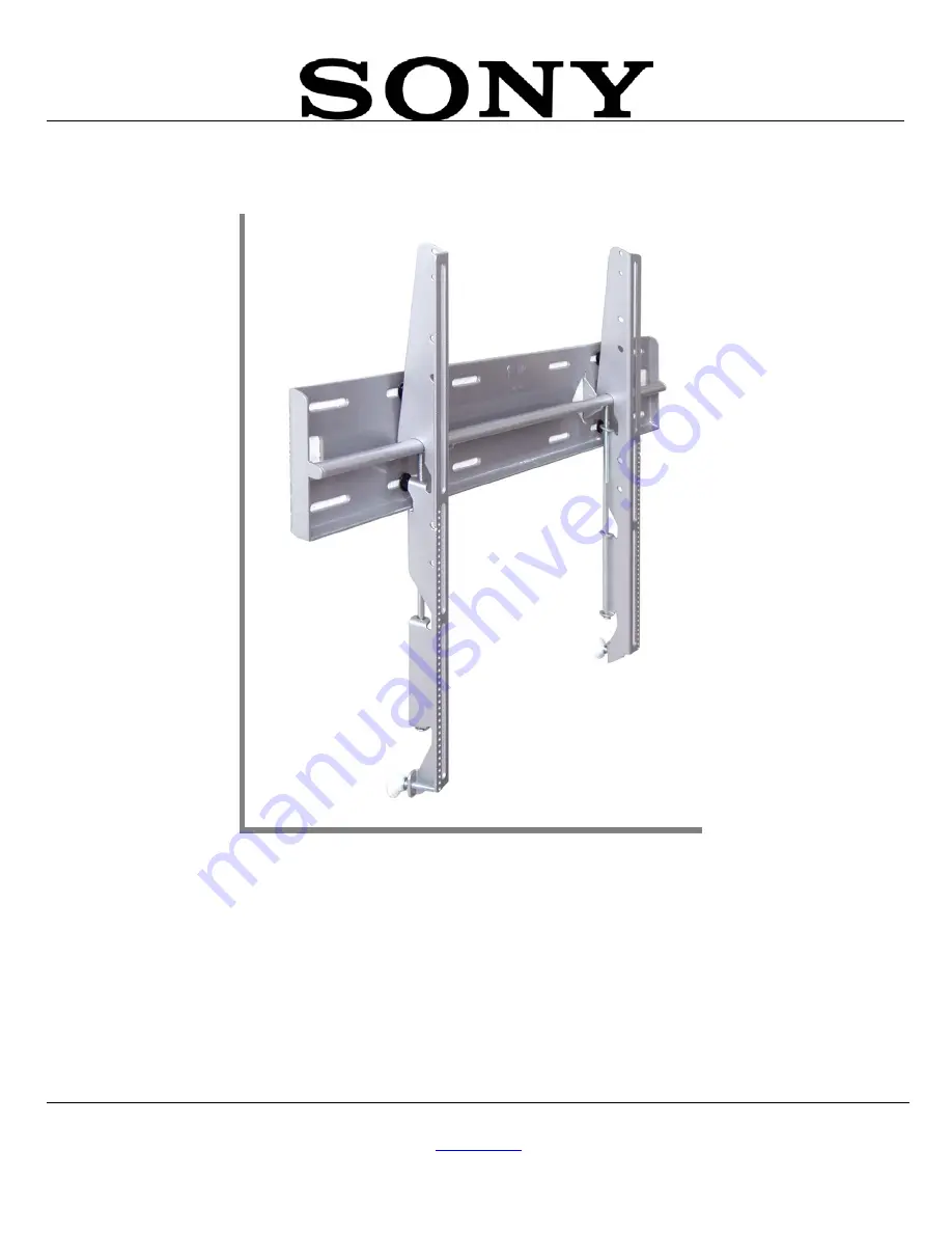
INSTALLATION MANUAL
SFM1
Sony Electronics, Inc.
16540 West Bernardo Drive
San Diego, CA 92127
www.sony.com
Page 1: ...INSTALLATION MANUAL SFM1 Sony Electronics Inc 16540 West Bernardo Drive San Diego CA 92127 www sony com ...
Page 2: ...PBL 110 Projector Mount Page 2 Installation Manual ...
Page 3: ...6 Mounting Bracket Positioning 6 Griplates 9 Wood Stud Location 10 Marking The Mounting Points 11 Securing The Wall Plate To The Wooden Studs 12 Securing The Wall Plate To A Concrete Wall 13 Securing The Flat Panel To The Wall Mount 14 Lateral Shift Adjustment 14 Security Cable 15 Technical Specifications 16 Warranty 17 Customer Support 17 Notes 18 ...
Page 4: ...THESE INSTALLATION INSTRUCTIONS IN AN EASILY ACCESSIBLE LOCATION FOR FUTURE REFERENCE Indicates that the power plug is to be disconnected from the power outlet Contact Sony Electronics with any questions Safety precautions must be taken at all times Warning and Caution statements Do not install on a structure that is prone to vibration movement or chance of impact Failure to do so could result in ...
Page 5: ...nd or damaged please stop the installation and contact Sony Electronics 800 222 7669 Wall Plate 1ea Mounting Brackets Left and Right Griplates 4ea 5 16 x 3 Lag Bolts 4ea Wooden studs only M6 x 12mm 4ea 5 16 Flat Washers Metal 8ea Flat Panel List SONY Fits All Sony Professional plasma and Large LCD Panels Installation Tools Phillips Head Screw Driver Portable Drill Drill Bit Level Soft Material Bla...
Page 6: ...ULT IN SERIOUS INJURY AND POSSIBLE DAMAGE TO THE FLAT PANEL 1 Once the flat panel is inverted use a measuring tape to find the center of your flat panel measuring from outside to outside of the chassis Figure 1 2 Using a pencil lightly mark the center of your flat panel Figure 2 C L L C Figure 1 Flat Panel Mount Location Figure 2 Marking the Mount Mounting Bracket Positioning 1 Install the nylon s...
Page 7: ... Manual Page 7 Figure 3 Mounting Bracket Positioning Figure 4 Mounting Bracket Installation Nylon Spacers If Applicable See Chart Inverted Flat Panel Center Mark Mounting Brackets Bottom of Flat Panel Arrows Facing OUT ...
Page 8: ...he side of the bracket Figure 5 Figure 5 Locating the Center of the Flat Panel 3 Match the center of the viewing guide with the centerline you marked in Step 1 Figure 6 C L Figure 6 Adjusting the Mounting Brackets Align the Mounting Brackets Bottom of the Flat Panel Mounting Bracket Bottom of Flat Panel Center of Viewing Guide Center of Flat Panel ...
Page 9: ... brackets are aligned secure the Griplate to the flat panel NOTE The dimples of the top plates have to be facing up and the bottom dimples must be facing down Use 1 Griplate per mounting point Figure 8 NOTE Leave a gap on both mounting brackets as shown on this diagram CAUTION Do not over tighten the mounting hardware DIMPLES FACING UP 3 4 DIMPLES FACING UP DIMPLES FACING DOWN DIMPLES FACING DOWN ...
Page 10: ...s have three 16 and 12 mounting slot positions 16 Figure 9 Locating the Wooden Stud 3 Measure from the floor to the desired viewing height and mark the wall Figure 10 NOTE This marking will reference the center of your flat panel display once mounted to the wall 16 Figure 130 Measuring the Height Wooden Studs behind the Wall Structure Wooden Studs Stud Finder Measure and Mark the Desired Viewing H...
Page 11: ... the wall plate to the reference line and mark the four 4 lag bolt mounting points through the wall plate slots on the wall 2 Level the wall plate with the reference arrow pointing up to the ceiling Figure 11 16 Figure 11 Marking the Mounting Points Wall Plate Mounting Slots Level Wood Studs ...
Page 12: ...ure 12 Mounting Surfaces Securing the Wall Plate to the Wooden Studs 1 Level and secure the plate to the wall with the reference arrow facing up to ceiling 2 Secure the plate using four 4 5 16 lag bolts and flat washers Figure 13 CAUTION Do not overtighten the lag bolts NOTE Use a minimum diameter of 5 16 x 3 long wooden screws Figure 13 Securing the Wall Plate Drill Gun Pilot Holes Level 5 16 x 3...
Page 13: ...e to the wall with the reference arrow facing up to the ceiling 2 Use a minimum diameter of 5 16 x 2 wedge anchors Figure 14 CAUTION Do not overtighten the wedge anchor bolts NOTE Use a minimum diameter of 5 16 x 2 long wedge anchors Figure 14 Concrete Installation 5 16 x 2 Wedge Anchors 4ea Wall Plate ...
Page 14: ...HT mounting brackets secured to the flat panel and insert the top hooks from each bracket to the rod on the wall plate Figure 15 Figure 15 Securing the Flat Panel Lateral Shift Adjustment 1 Make any lateral shift adjustment and lock it by tightening the two 2 20 Phillips screws found on the bottom of the mounting brackets Figure 16 2 Use the foot leveler to adjust your plasma CAUTION Do not over t...
Page 15: ...SFM1 Installation Manual Page 15 Security Cable 1 2 3 4 ...
Page 16: ...1 2 C L 3 500 88 9 C L 5 000 127 16 000 406 4 24 290 616 97 16 000 406 4 21 790 553 4 1 245 31 75 A B C D E F G H B A F H 21 790 553 4 A Wall plate B Mounting brackets C Griplate D Mounting hardware E Safety screws F Leveling feet G Wood stud H 5 16 x 3 Lag screws and flat washers Figure 17 Technical Specifications ...
Page 17: ...materials and workmanship Sony Electronics is not liable for improper installation that results in damage to mounts adapters display equipment or personal injury Customer Support In the event of missing and or damage equipment or technical questions the following information can help in the completion of the installation Customer Service 877 350 3477 ...
Page 18: ...SFM1 Page 18 Installation Manual Notes Sony Electronics Inc 16540 West Bernardo Drive San Diego CA 92127 800 222 7669 www sony com Sony 2005 ...