2-7.
RE-326 Board
Preparation
1.
Remove the outside panel assembly. (Refer to
2.
Remove the bracket (WA) assembly. (Refer to
“2-6. Wi-Fi Module/SD-58 Board”
)
Procedure
1.
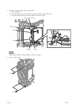
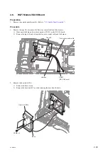
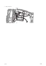
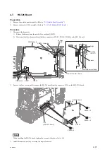
Disconnect the harnesses.
1) Release the harness from the notch of the cushion (LIGHT).
2) Disconnect the three harnesses from the three connectors (CN100, CN101, CN800) on the RE-326 board.
RE-326 board
Cushion
(LIGHT)
Cushion
(LIGHT)
Wall of the main frame
Wall of the main frame
Harness
Notch
Harnesses
Harness
CN101
CN100
CN800
2.
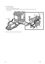
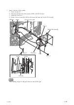
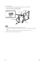
Remove the four screws, and disconnect the RE-326 board from the connector (CN1) on the MB-1210 board.
RE-326 board
PSW2 x 5
PSW2 x 5
(a)
(d)
(c)
(b)
PSW2 x 5
PSW2 x 5
CN300
CN1
(MB-1210 board)
Note
When installing the RE-326 board, tighten the screws in the order of (a) to (d).
3.
Install the removed parts by reversing the steps of removal.
PXW-X500
2-37
Summary of Contents for PXW-X500
Page 1: ...SOLID STATE MEMORY CAMCORDER PXW X500 SERVICE MANUAL 1st Edition ...
Page 4: ......
Page 8: ......
Page 10: ......
Page 54: ......
Page 87: ...3 Remove the tape AS Tape AS PXW X500 2 33 ...
Page 109: ...4 Install the removed parts by reversing the steps of removal PXW X500 2 55 ...
Page 158: ......
Page 183: ......
Page 184: ...PXW X500 SY PXW X500 CN J E 9 878 582 01 Sony Corporation Printed in Japan 2014 11 08 2014 ...

