4-3.
Description of SERVICE Menu
4-3-1.
SERVICE Menu
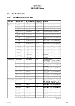
The service menu allows parameter adjustment (such as correction of individual differences of image pickup device and
lens) that varies from unit to unit.
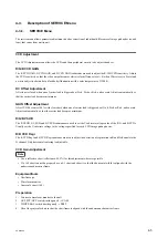
CCD Adjustment
The CCD Adjustment menu allows the CCDs and their peripheral circuits to be adjusted and set.
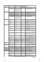
R/G/B CCD GAIN
The R CCD GAIN, G CCD GAIN, and B CCD GAIN submenus are used to adjust the R/G/B CCD sensitivity. Adjust
the CCD sensitivity so that the video output becomes white (color difference level = 0) when White is set to Preset and
a white subject is shot under a black body illumination with a color temperature of 3200 K.
DC Offset Adjustment
After lens is closed, when one of carrier leak is bigger about G-ch, B-ch or R-ch, and execute. Adjusts automatically so
that the carrier leak becomes minimum.
GAIN Offset Adjustment
After CCDE becomes 100 % with clear chart, when one of carrier leak is bigger about G-ch, B-ch or R-ch, and execute.
Adjusts automatically so that the carrier leak becomes minimum.
R/G/B VSUB
The R VSUB, G VSUB, and B VSUB submenus are used to set the V substrate voltage value of the R, G, and B CCDs.
Usually set the V substrate voltage to the voltage specified for each CCD image pickup device.
R/B CCD Regi
The R CCD Regi and B CCD Regi submenus are used to adjust the deviation of registration in R and B channels to the
G channel. Only horizontal centering is adjustable.
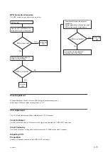
CCD Gain Adjustment
Note
• Use a reflective chart (reflectance: 89.9%) for this adjustment wherever possible.
• If a 16:9 chart cannot be prepared, use a 4:3 chart and shoot it so that the horizontal width is aligned with the
underscanned monitor frame.
Equipment/tools
• Oscilloscope
• Waveform monitor
• Grayscale chart (16:9)
Preparation
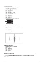
1.
Connect a waveform monitor to the unit.
2.
OUTPUT/DCC switch (inside panel) → CAM
3.
WHITE BAL switch (inside panel) → PRST
4.
Shoot the grayscale chart so that the chart frame is aligned with the underscanned monitor frame.
PXW-X500
4-5
Summary of Contents for PXW-X500
Page 1: ...SOLID STATE MEMORY CAMCORDER PXW X500 SERVICE MANUAL 1st Edition ...
Page 4: ......
Page 8: ......
Page 10: ......
Page 54: ......
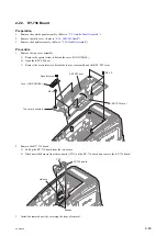
Page 87: ...3 Remove the tape AS Tape AS PXW X500 2 33 ...
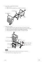
Page 109: ...4 Install the removed parts by reversing the steps of removal PXW X500 2 55 ...
Page 158: ......
Page 183: ......
Page 184: ...PXW X500 SY PXW X500 CN J E 9 878 582 01 Sony Corporation Printed in Japan 2014 11 08 2014 ...


