background image

Adjustment Using the Menus

25


WFM/ALM/VECTOR (waveform monitor, 
audio level meter, and vectorscope) 
SETTING

Submenu

Setting

T/C

Selects ON to display the time code 
display and OFF not to display.

FORMAT

Sets the time code format.

VITC

: To display the time code 

in VITC format.

LTC

: To display the time code in 
LTC format.

POSITION

Sets the position of the time code 
display. You can select between 1 
and 2.

1

: Top

2

: Bottom

TRANSPARENCY

Selects BLACK or HALF 
(transparent) for the background of 
T/C display.

BLACK

: The background 

becomes black. Displayed 
image is hidden behind the 
background.

HALF

: The background becomes 

transparent. Displayed 
image appears under the T/C 
display.

Submenu

Setting

DISPLAY

Select ON to display the WFM 
(waveform monitor), ALM (audio level 
meter), or VECTOR (vectorscope); or 
OFF not to display.

D I S P L AY:  

xxx

W F M / A L M / V E C T O R :  

xxxxxx

P O S I T I O N :  

x

C O L O R :  

xx

I N T E N S I T Y:  

x

Z O O M :  

xxx

L I N E   S E L E C T :  

xxx

L I N E   P O S I T I O N :  

xxx

TA R G E T :  

xxx

USER CONFIG – WFM/ALM/VECTOR SETTING

WFM/ALM/
VECTOR

Sets the display settings for WFM/ALM/
vectorcope.

WFM

: Displays the wave form 

monitor.

ALM

: Displays the audio level meter.

VECTOR

: Displays the vectorscope.

When WFM is selected, the waveform 
and audio level are displayed. When 
ALM is selected, the audio level is 
displayed in eight channels.
When VECTOR is selected, the color 
component of the image signal and the 
audio levels are displayed.
When SDI signal is input, the audio 
levels for channels selected in SDI 
AUDIO SETTING are displayed.

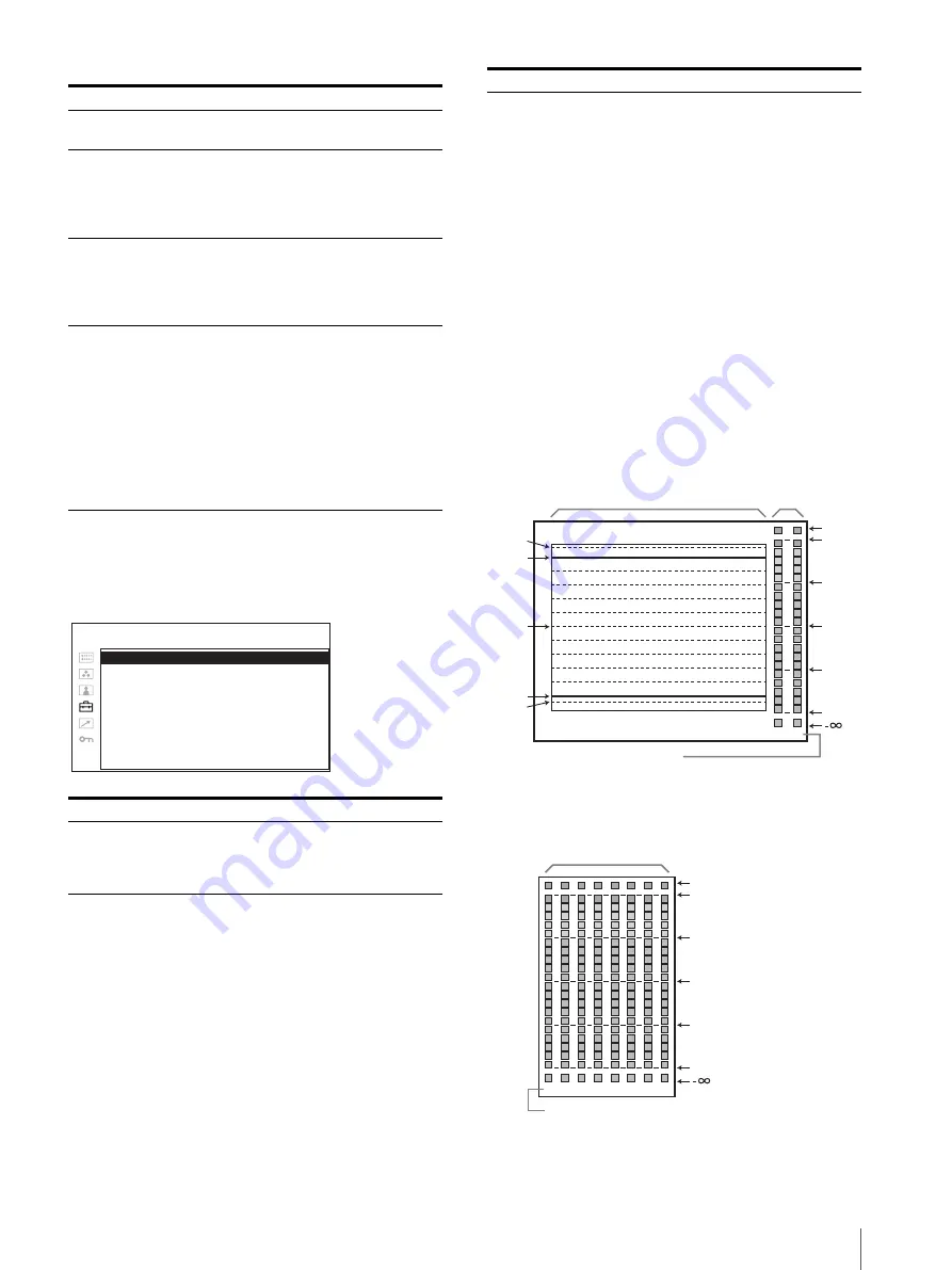
Each display type is illustrated below. 
(The waveform percentage and audio 
level units/values do not appear on the 
display.)

When WFM is selected

When ALM is selected

Submenu

Setting

-4%

0%

50%

100%

0

OVER

(dB)

-10

-20

-30

-60

1

2

109%

Audio level

Waveform

Channel number 
(The channel number which is selected in 
SDI AUDIO SETTING is displayed.)

0

(dB)

-10

-20

-30

-60

OVER

1 2 3 4 5 6 7 8

Audio level

Channel number
(Displayed in eight channels, including the channel 
which is selected in SDI AUDIO SETTING.)

Summary of Contents for PVM-741

Page 1: ...Professional Video Monitor Operating Instructions Before operating the unit please read this manual thoroughly and retain it for future reference PVM 741 4 434 264 12 1 2012 Sony Corporation ...

Page 2: ...d to rain or moisture does not operate normally or has been dropped WARNING To reduce the risk of fire or electric shock do not expose this apparatus to rain or moisture To avoid electrical shock do not open the cabinet Refer servicing to qualified personnel only WARNING THIS APPARATUS MUST BE EARTHED WARNING When installing the unit incorporate a readily accessible disconnect device in the fixed ...

Page 3: ...oved in this manual could void your authority to operate this equipment All interface cables used to connect peripherals must be shielded in order to comply with the limits for a digital device pursuant to Subpart B of Part 15 of FCC Rules This device complies with Part 15 of the FCC Rules Operation is subject to the following two conditions 1 this device may not cause harmful interference and 2 t...

Page 4: ...el 9 Input Signals and Adjustable Setting Items 11 Rear Bottom Panel 12 Installing the Handle 13 Installing the Arm Mount Bracket 14 Installing to the Rack Using MB 531 14 Power Supply 15 Attaching the AC Adaptor 15 Connecting the AC Power Cord 15 Selecting the Default Settings 16 Selecting the Menu Language 17 Using the Menu 18 Adjustment Using the Menus 20 Items 20 Adjusting and Changing the Set...

Page 5: ...Do not place a heavy object on the monitor s screen This may cause the screen to lose uniformity The screen and the cabinet become warm during operation This is not a malfunction On Burn in Due to the characteristics of the material used in the OLED panel for its high precision images permanent burn in may occur if still images are displayed in the same position on the screen continuously or repea...

Page 6: ...water droplets may form on the interior of the product This phenomenon is known as dew condensation This product does not come with a feature that warns users of dew condensation If water droplets are found on the casing turn off the power and wait until the condensation disappears before using On Repacking Do not throw away the carton and packing materials They make an ideal container which to tr...

Page 7: ...Rich color reproduction An OLED panel s self luminescence also allows for great color reproduction across the entire spectrum in practically any shade or brightness Sony s Super Top Emission2 OLED panel The 7 4 type Quarter HD 960 540 OLED panel features Sony s Super Top Emission structure Unlike the conventional bottom emission structure of TFT Sony s OLED panel can reproduce a crisper image due ...

Page 8: ...he Operation Manual of the BKM 15R or BKM 16R Monitor Control Unit optional Closed caption The EIA CEA 608 and EIA CEA 708 standard closed caption signals superimposed on an SDI signal are displayed Illuminated control panel The characters that represent the names of the buttons on the control panel can be illuminated so it is visible in the dark The brightness of the LED has two levels and varies...

Page 9: ...ignals from the speaker are output from the AUDIO OUT connector on the rear see page 12 Audio signals will not be output when headphones are connected to the i jack e Stand Pull the stand toward you to tilt the monitor screen by 15 When using the optional VF 510 Monitor ENG Kit set the stand at positions B and C see Using the stand on page 10 f Input select buttons Press to monitor the signal inpu...

Page 10: ... signal format is displayed on the screen RETURN button When the menu is displayed press the button to reset the value of an item to the previous value except some items When the menu is not displayed press the button to display the name of the function selected in FUNCTION BUTTON SETTING of the USER CONFIG menu MENU button Press to display the on screen menu Press again to clear the menu i 1 stan...

Page 11: ...ay be misplaced cropped or missing Input signal Item Video B W SDI HDMI SD HD 3G SD HD CONTRAST a a a a a a a BRIGHTNESS 1 a a a a a a a CHROMA a a a a a a PHASE a NTSC APERTURE a a a a a a a COLOR TEMP a a a a a a a COLOR SPACE a a a a a a a AUTO CHROMA PHASE a ACC a CTI a V SHARPNESS a a a a NTSC SETUP a NTSC a 480 60I SCAN a a a a a a a ASPECT a a a a MARKER a a a a a a a BLUE ONLY a a a a a a ...

Page 12: ...onnector Connect to the audio outputs of external equipment such as a VCR OUT connector Outputs the audio signal which is selected by the input select button on the front panel When SDI signal is selected either the audio signal of the channel which is selected in AUDIO SETTING of the USER CONFIG menu or the audio signal from the AUDIO IN connector is output d PARALLEL REMOTE connector modular con...

Page 13: ... digital picture and sound The HDMI specification supports HDCP High bandwidth Digital Content Protection a copy protection technology that incorporates coding technology for digital video signals Note Use HDMI compliant cable optional with HDMI logo g EJECT button While sliding this button remove the AC adaptor h Tripod socket hole 1 4 20UNC 3 8 16UNC When using a tripod secure it to the monitor ...

Page 14: ...g to the Rack Using MB 531 You can attach up to two monitors to the rack by using the optional MB 531 Mounting Bracket 1 Attach the mounting bracket to the monitor For details on attaching the mounting bracket refer to the Mounting Instructions of the MB 531 2 Attach the unit to the rack with four screws Note The screws are not supplied Prepare screws according to the rack Arm mount bracket ...

Page 15: ...t unplug the AC power cord and then remove the AC adaptor Do not carry the monitor by holding the AC adaptor Connecting the AC Power Cord Attach the AC adaptor to the monitor and then connect the supplied AC power cord Attach the AC plug holder to the AC power cord and connect it to the AC IN connector so that the cord does not come loose AC power cord supplied AC plug holder supplied ...

Page 16: ...trol to narrow the area further and then press the menu selection control The confirmation screen is displayed Confirm the selected area If the setting is wrong press the RETURN button to return to the previous screen 3 3 4 5 3 1 2 COLOR TEMP NTSC SETUP COLOR SPACE 1NORTH AMERICA D65 7 5 ITU 709 2LATIN AMERICA PAL PAL N AREA ARGENTINA D65 0 ITU 709 PARAGUAY D65 0 ITU 709 URUGUAY D65 0 ITU 709 NTSC...

Page 17: ...Italian Japanese Chinese for displaying the menu and other on screen displays ENGLISH English is selected in the default setting The current settings are displayed in place of the x marks on the illustrations of the menu screen 1 Turn on the unit 2 Press the MENU button The menu appears The menu presently selected is shown in yellow 3 Turn the menu selection control to select SYSTEM SETTING of the...

Page 18: ...yed in place of the x marks on the illustrations of the menu screen 1 Press the MENU button The menu appears The menu presently selected is shown in yellow 2 Turn the menu selection control to select a menu then press the menu selection control NTSC SETUP xxxxxx FORMAT DISPLAY xxxxxx LANGUAGE ENGLISH POWER SAVING xxxxxx I P MODE xxxxxxx LED BRIGHTNESS xxxxxx RGB RANGE xxxxxx SCREEN SAVER xxxxxx SD...

Page 19: ...e menu selection control to confirm the setting When returning the adjustment or setting to the previous value Press the RETURN button before pressing the menu selection control Notes An item displayed in black cannot be accessed You can access the item if it is displayed in white If the key inhibit has been turned on all items are displayed in black To change any of the items turn the key inhibit...

Page 20: ...SAVING I P MODE LED BRIGHTNESS RGB RANGE SCREEN SAVER SD PIXEL MAPPING MARKER SETTING MARKER ENABLE MARKER SELECT CENTER MARKER SAFETY AREA MARKER LEVEL MARKER MAT T C DISPLAY SETTING T C FORMAT POSITION TRANSPARENCY WFM ALM VECTOR waveform monitor audio level meter and vectorscope SETTING DISPLAY WFM ALM VECTOR POSITION COLOR INTENSITY ZOOM LINE SELECT LINE POSITION TARGET FOCUS SETTING FOCUS MOD...

Page 21: ...BIAS COPY FROM xxx COLOR SPACE x COLOR TEMP SPACE Submenu Setting COLOR TEMP Selects the color temperature from among D65 D93 and USER setting Note If you measure the color temperatures of different display types such as CRT LCD or OLED by using a common or general color analyzer that is based on CIE 1931 and adjust the xy chromaticity to the same value the appearance may be different because of o...

Page 22: ...s enabled START The auto adjustment starts when you display the color bar signals Full SMPTE EIA on the screen and press the menu selection control After adjusting the color intensity press the MENU button to clear the adjustment screen After the adjustment is done correctly the AUTO ADJ VALUE is automatically set to ON PICTURE CONTROL Adjusts the picture ACC Auto Color Control Sets ACC circuit on...

Page 23: ...USER CONFIG SYSTEM SETTING I P MODE picture delay minimum Selects to set the delay by the picture processing to the minimum level when the interlace signal is input INTER FIELD Mode for giving precedence to the picture quality Performs interpolation depending on the movement of the images between the fields It takes longer than the other setting modes to process the picture FIELD MERGE The process...

Page 24: ...ARKER SELECT xxx CENTER MARKER xx SAFETY AREA xxx MARKER LEVEL x MARKER MAT xxx USER CONFIG MARKER SETTING Submenu Setting MARKER ENABLE Selects ON to display the marker and OFF not to display Note When NATIVE is selected in the SCAN setting the marker is not displayed To display the marker select a setting other than NATIVE MARKER SELECT Selects the aspect ratio according to the film when the fra...

Page 25: ...OOM xxx LINE SELECT xxx LINE POSITION xxx TARGET xxx USER CONFIG WFM ALM VECTOR SETTING WFM ALM VECTOR Sets the display settings for WFM ALM vectorcope WFM Displays the wave form monitor ALM Displays the audio level meter VECTOR Displays the vectorscope When WFM is selected the waveform and audio level are displayed When ALM is selected the audio level is displayed in eight channels When VECTOR is...

Page 26: ... Q Channel number The channel number which is selected in SDI AUDIO SETTING is displayed Submenu Setting FOCUS MODE Switches the focus mode STD An image with sharpened edges is displayed COLOR Displays the intensified areas of images with color selected in COLOR below OFF FOCUS MODE is deactivated COLOR Selects the displayed intensified color from white W red R green G blue B and yellow YL FREQUEN...

Page 27: ...ain to hide the adjustment screen However the picture brightness remains adjustable Turn the menu selection control right to increase the brightness and turn left to decrease it CONTRAST Press the button to adjust the picture contrast Press the button to display the adjustment screen and adjust the picture contrast Press again to hide the adjustment screen However the picture contrast remains adju...

Page 28: ...ote The format display flips with the picture The flipped picture returns to normal when the on screen menu is displayed The picture automatically returns to the flipped picture when the on screen menu disappears Scan mode image Selecting a display area While selecting NATIVE in the SCAN modes with 1080i or1080p input signal parts of the image are cut off by the screen panel Those parts can be dis...

Page 29: ...matically 608 VBI 3 when SD SDI signal is input or to display automatically 708 1 when HD SDI signal is input AUTO2 Select this to display automatically 608 VBI 3 when SD SDI signal is input or to display automatically 608 708 2 when HD SDI signal is input 708 Select this to display 708 1 when HD SDI signal is input 608 708 Select this to display 608 708 2 when HD SDI signal is input 608 VBI Selec...

Page 30: ...CONNECTION xxx REMOTE PARALLEL REMOTE 1 PIN xxxx 2 PIN xxxx 3 PIN xxxx 4 PIN xxxx 6 PIN xxxx 7 PIN xxxx 8 PIN xxxx FORCED TALLY xxx REMOTE PARALLEL REMOTE Submenu Setting PARALLEL REMOTE Selects the PARALLEL REMOTE connector pins for which you want to change the function You can assign various functions to 1 to 4 pins and 6 to 8 pins The following lists the functions you can assign to the pins No ...

Page 31: ...mode to be used OFF SERIAL REMOTE does not function ETHERNET The monitor is controlled by the command of Ethernet BKM 15R 16R Sets BKM 15R or BKM 16R MONITOR Sets the monitor setting MONITOR ID Sets the ID of the monitor GROUP ID Sets the group ID of the monitor IP ADDRESS Sets the IP address SUBNET MASK Sets the subnet mask 255 255 255 000 DEFAULT GATEWAY Sets the default gateway on or off ADDRES...

Page 32: ...iagonal 188 0 mm 7 1 2 inches Effective picture size H V 163 9 92 2 mm 6 1 2 3 5 8 inches Resolution H V 960 540 pixels Quarter HD Aspect 16 9 Pixel efficiency 99 99 Panel drive RGB 10 bit Viewing angle Panel specification 89º 89º 89º 89º typical up down left right contrast 10 1 Normal scan 0 scan Over scan 5 over scan Color temperature D65 D93 USER Warm up time Approx 30 minutes To provide stable...

Page 33: ...1 Using the CD ROM Manual 1 Optional accessories Mounting bracket MB 531 Mounting panel MB 532 Monitor ENG kit VF 510 Design and specifications are subject to change without notice Pin assignment PARALLEL REMOTE connector Modular connector 8 pin You can allocate functions using the REMOTE menu see page 30 Note Switching functions continuously allows at least 200 msec to do so Otherwise it may not ...

Page 34: ...4 4 4 RGB of 3G SDI signals are supported 4 10 bit 4 2 2 Y Cb Cr of 3G SDI signal is supported 5 10 bit 4 4 4 Y Cb Cr of 3G SDI signal is supported System Compo site SD HD 3G HDMI 575 50i PAL a a a 480 60i NTSC 1 a a a 576 50p a 480 60p 1 a 640 480 60p 1 a 1080 24PsF 1 2 a a 3 1080 25PsF 2 a a 3 1080 30PsF 1 2 a 3 1080 24p 1 a a 3 a 1080 25p a a 3 a 1080 30p 1 a a 3 a 1080 50i a a 3 a 1080 60i 1 a...

Page 35: ...rm mount bracket 222 4 8 7 8 166 6 5 8 183 5 7 1 4 17 5 23 32 161 8 6 3 8 148 8 5 7 8 130 5 1 8 70 2 7 8 60 2 3 8 161 5 6 3 8 149 6 6 5 6 1 4 13 17 32 1 4 20UNCMaximum depth 6 mm 1 4 inch 3 8 16UNC Maximum depth 6 mm 1 4 inch 4 M3 Maximum depth 6 mm 1 4 inch 173 6 6 7 8 55 2 2 1 4 16 21 32 33 2 1 5 16 25 1 100 4 27 1 1 8 Unit mm inches 38 1 1 2 1 4 20UNC Maximum depth 6 mm 1 4 inch 3 8 16UNC Maxim...

Page 36: ...Sony Corporation ...

Reviews: