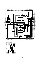
— 93 —
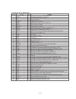
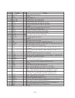
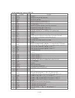
• IC301 System Control (M30600E8FP)
Function
Jog detection input from the CXD2535CR.
Focus OK input from the CXD2535CR.
C1 error test output
ADER, C2 error test output
SUBQ/ATIP sync input from the CXD2535CR.
Wired remote control input
Power down detection input
External data bus width switching input (Fixed to “L”.)
Processor mode switching input (Fixed to “L”.)
CXD2536CR recording data output timing and magnetic head control output
FG input from the spindle motor.
Reset input
Clock output (8.6 MHz)
Ground (0V)
Clock input (8.6 MHz)
Power supply (+5V)
NMI input (Fixed to “H”.)
IC for RS232C. Interrupt request input from the M66230FP.
Keyboard communication clock input
DIN SUBQ sync input from the digital-in receiver LC89051V (IC410).
Interrupt request input from the high-speed dubbing CXD2536CR (IC407).
Interrupt request input from the CXD2536CR (IC401).
Encode/decode mode switching output to the CXD2535CR.
Unlock detection input from the digital-in receiver LC89051V.
Not used.
Command latch output to the high-speed dubbing CXD2536CR (IC407).
Command latch output to CXD2536CR (IC401), CXD2535CR, LC89051V, CXD8517Q.
Command latch output to the audio D/A converter CXD8567AM.
Chip select output to the FL tube display driver.
Chip select output to the variable pitch controller LC72130M.
Serial bus write data output
Serial bus read data input
Serial bus clock output
RS232C DSR input
Write data output to the FL tube display driver and the variable pitch controller.
Read data input from the variable pitch controller.
Clock output to the FL tube display driver and the variable pitch controller.
Keyboard communication data input
External data bus ready input (Fixed to “H”.)
External data bus address latch enable output
SHCK
FOR
C1
ADER, C2
SQSY
SIRCS
PDOWN
BYTE
CNVSS
SCTX
FG
XREST
XOUT
GND
XIN
VCC
NMI
232XINT
KBCK
DQSY
XINT2
XINT1
REC
ERROR
––––
XLAT2
XLAT1
DALAT
FLCS
CE
SWDT
SRDT
SCLK
DSR
TXD
RXD
CLK
KBDATA
XRDY
ALE
1
2
3
4
5
6
7
8
9
10
11
12
13
14
15
16
17
18
19
20
21
22
23
24
25
26
27
28
29
30
31
32
33
34
35
36
37
38
39
40
I
I
O
O
I
I
I
I
I
O
I
I
O
–
I
–
I
I
I
I
I
I
O
I
I
O
O
O
O
O
O
I
O
I
O
I
O
I
I
O
Function
Pin No.
Pin Name
I/O
Summary of Contents for MDS-B5
Page 2: ... 2 ...
Page 5: ... 5 SECTION 1 GENERAL This section is extracted from instruction manual ...
Page 6: ... 6 ...
Page 7: ... 7 ...
Page 8: ... 8 ...
Page 9: ... 9 ...
Page 10: ... 10 ...
Page 11: ... 11 ...
Page 12: ... 12 ...
Page 13: ... 13 ...
Page 14: ... 14 ...
Page 15: ... 15 ...
Page 16: ... 16 ...
Page 17: ... 17 ...
Page 18: ... 18 ...
Page 19: ... 19 ...
Page 20: ... 20 ...
Page 21: ... 21 ...
Page 22: ... 22 ...
Page 23: ... 23 ...
Page 24: ... 24 ...
Page 25: ... 25 ...
Page 26: ... 26 ...
Page 27: ... 27 ...
Page 28: ... 28 ...
Page 29: ... 29 ...
Page 30: ... 30 ...
Page 31: ... 31 ...
Page 32: ... 32 ...
Page 49: ......
Page 50: ......
Page 51: ......
Page 52: ......
Page 53: ......
Page 54: ......
Page 55: ......
Page 56: ......
Page 57: ......
Page 58: ......

