Adjustment Using the Menus
85
DISPARITY SIM. (disparity simulation)
Press the button to change the phase of left/right signals
for 3D image display. You can monitor the depth of 3D
images using simulated 3D effect. Press the
+
or –
button to adjust the phase of the selected signal(s).
Select the signal(s) you want to adjust from
DISPARITY SIM. under the 3D SETTING menu before
using this function button. Pressing the button again
stores the setting values you set. Install BKM-250TGM
to display HD-SDI signal in 3D.
Note
This function is only available when 3G-B*, DUAL,
AUTO1, or AUTO2 is selected in 3D SIGNAL
FORMAT.
* Install BKM-250TGM to display HD-SDI signal in 3D.
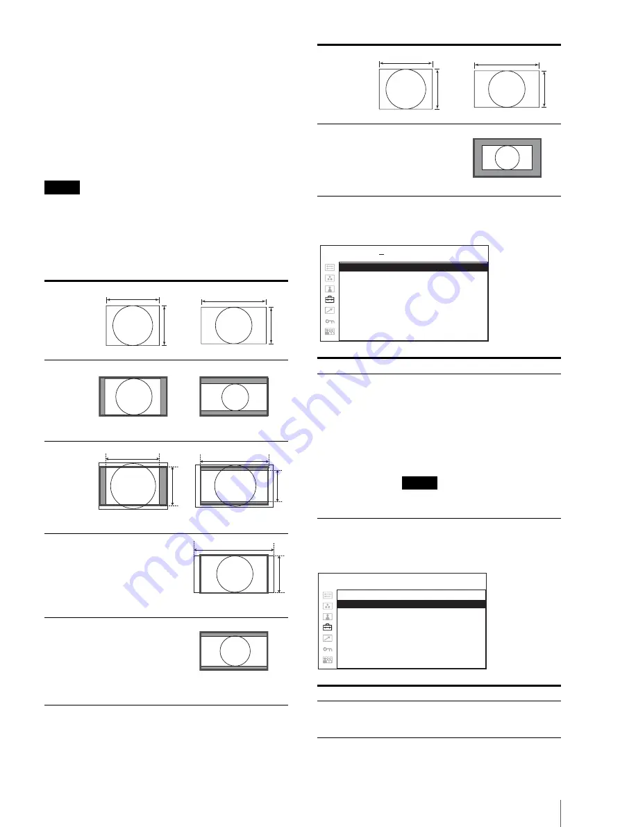
Scan mode image
COMPUTER DETECT
OPTION DVI SETTING
* This settings are displayed only when a BKM-256DD is installed.
–
–
1080P is effective only when BKM-250TGM is installed.
In
put
4
3
16
9
NORM
A
L
(z
er
osc
an)
4 : 3
1600 × 1200
16: 9
1920 × 1080
OV
E
R
(20%
o
v
er
sc
an)
4
3
1600 × 1200
16
9
1920 × 1080
FU
L
L
16
9
1920 × 1200
NA
T
IV
E
(1
0
8
0
i,
10
80
P)
1920 × 1080
–
Submenu
Setting
COMPUTER
DETECT
The appropriate preset memory is set for
the signal from DVI and HD15 input
connector. Select “PRESET1” for the
standard computer signal. Select
“PRESET2” to “PRESET8” when the
computer signal is not standard (on
page 93).
The preset memory is set for each input
connector of DVI and HD15.
Note
“PRESET7” and “PRESET8” will only
be displayed when “DVI” is selected.
Submenu
Setting
EXT 5V(IN)
Selects ON to output external 5 V
power from the DVI input
connectors and OFF not to output.
Input
4
3
16
9
NA
T
IV
E
(7
2
0
P
)
1280 × 720
DV I :
xxxxx
H D 1 5 :
xxxxx
USER CONFIG
COMPUTER DETECT
OPTION DVI SETTING
E X T 5 V ( I N ) :
xx
E X T 5 V ( O U T ) :
xx
E D I D U P D AT E :
xxxxx
E D I D S TAT U S :
xxxx
M O D E L
S E R .
USER CONFIG – OPTION DVI SETTING


