background image

Ad
minis

tra

ting t

he Camer

a

Recording Images in Memory — Image memory setting Page

35

Schedule No.

When 

Use scheduler

 is selected on the Available period 

menu, select the schedule you want the alarm mode 
being available.
Click to select the check box(es) 

1

 to 

6

.  You can select 

multiple schedules.
To check the contents of schedules, click 

Schedule 

check

.  (See “Setting the Schedule — Schedule setting 

Page” on page 40.)

Alarm duration

Select the duration for which the alarm output is short-
circuited between 1 and 60 sec.

Timer mode setting Section

Schedule No.

Select the schedule you want to activate the alarm out 1 
timer mode.
Click to select the check box(es) 

1

 to 

6

.  You can select 

multiple schedules.
The alarm out 1 is short-circuited at the start time of the 
selected schedule,  and it switches to open at the end 
time.
To check the contents of schedules, click 

Schedule 

check

.  (See “Setting the Schedule — Schedule setting 

Page” on page 40.)

Recording Images in 
Memory 

— Image memory setting Page

When you click 

Image memory

 on the Administrator 

menu, the Image memory setting page appears.
Use this page to set up for the image memory function 
which captures a still image and records it in the built-in 
memory of the camera (about 8 MB) or the ATA 
memory card.  You can capture a still image at the 
moment when a trigger occurs by an external sensor 
input, the built-in activity detection function or a manual 
trigger button.  The captured still image is recorded in 
the built-in memory or the ATA memory card.  You can 
also record a still image periodically.
The recorded image file can be found or downloaded to 
the computer using the FTP server function. (See 
“Downloading Images from the Camera — FTP server 
setting Page” on page 31.)

For the verified cards, contact your authorized Sony 
dealer.

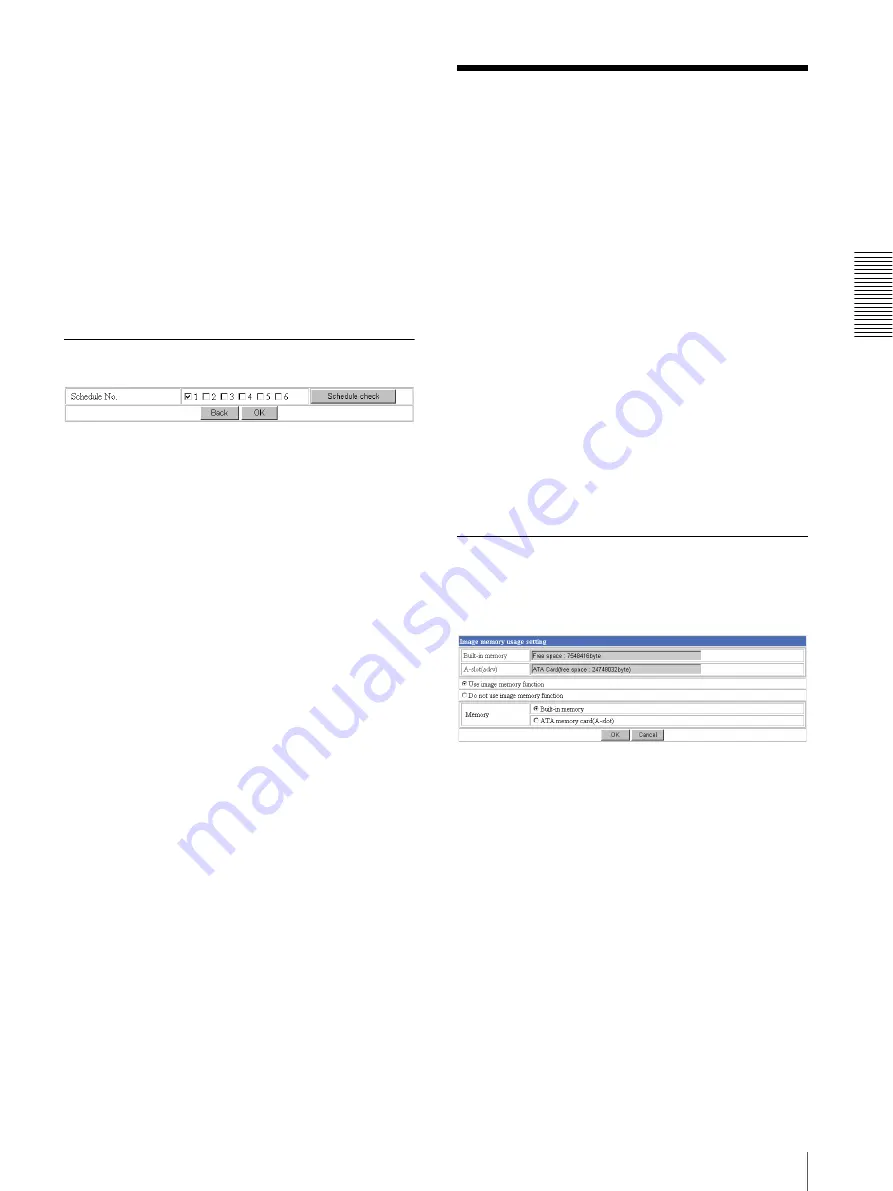
Activating/Deactivating the Image 
Memory Function — Image memory 
usage setting Page

Built-in memory

Displays the free space of the built-in memory of the 
camera.

A-slot

Displays the type of the PC card inserted into the PC 
card slot and its free card space.”

Use image memory function/Do not use 
image memory function

To activate the Image memory function, select 

Use 

image memory function

 and click 

OK

.  The Image 

memory setting page appears.
When you do not use the Image memory function, select 

Do not use image memory function

 and click 

OK

.

Summary of Contents for IPELA SNC-Z20N

Page 1: ...3 796 928 14 2 Network Camera 2003 Sony Corporation SNC Z20N Z20P User s Guide Software Version 1 0 ...

Page 2: ... Page 26 Activating Deactivating the Security Function Security usage setting Page 26 Setting the Security Function Securing setting Page 26 Sending Images to FTP Server FTP client setting Page 27 Activating Deactivating the FTP Client Function FTP client usage setting Page 27 Setting the FTP Client Function FTP client setting Page 27 Alarm mode setting Section 28 Periodical sending mode setting S...

Page 3: ...sing the Setup Program 43 Changing the Communication Bandwidth 45 Setting the Date and Time 45 Rebooting the Camera 45 Assigning the IP Address to the Camera Using ARP Commands 46 Using the SNMP 47 1 Inquiry Commands 47 2 Setting Commands 47 Storing an HTML File in the Built in Flash Memory 49 When using Windows XP Service Pack 2 51 When using Windows Vista 53 Index 56 ...

Page 4: ... you are monitoring may be protected by privacy and other legal rights and the responsibility for making sure you are complying with applicable laws is yours alone Access to the images and audio is protected only by a user name and the password you set up No further authentication is provided nor should you presume that any other protective filtering is done by the service Since the service is Int...

Page 5: ...se This User s Guide This User s Guide explains how to operate the SNC Z20N Z20P Network Camera from a computer The User s Guide is written to be read on the computer display As this section gives tips on using the User s Guide read it before you operate the camera Jumping to the related page When you read the User s Guide on the computer display click on the sentence to jump to the related page S...

Page 6: ... select Internet Options and Security tab in sequence 2 Click the Internet icon when using the camera via the Internet or Local intranet icon when using the camera via a local network 3 Set the slider to Medium or lower If the slider is not displayed click Default Level When using antivirus software in the computer When you use antivirus software in your computer the camera performance may be redu...

Page 7: ...l Java To enable Java Plug in Check Use JRE 1 6 0_01 for applet requires restart in Java Sun To install Java Plug in Download Java 2 Runtime Environment Standard Edition JRE from the website of Sun Microsystems Inc and install it by following the instructions on the installer ActiveX viewer It displays the main viewer page using ActiveX With this viewer you can display images at a high frame rate ...

Page 8: ...l 2 to Level 4 is required for this function Capture Captures a still image shot by the camera and stores it in the computer See Capturing a Monitor Image on page 12 Trigger Displays the trigger control parts on the image control section By clicking the trigger button you can control various applications manually See Controlling the Application Manually on page 11 User access right Level 3 or Leve...

Page 9: ...ge from the image control section on the main viewer page Image control section Selecting the frame rate Click the down arrow button in the Frame rate box and select the frame rate with which the images are transmitted from the drop down list You can select the frame rate from among the following SNC Z20N 1 2 3 4 5 6 8 10 15 20 25 Fastest SNC Z20P 1 2 3 4 5 6 8 12 16 20 Fastest The numbers indicat...

Page 10: ...Full see page 19 you can operate high magnification zoom optical zoom of 18 and electronic zoom of 12 giving 216 in total The electronic zoom will operate after the optical zoom When the Zoom mode menu is set to Optical only only optical zoom of 18 can operate In this case you can use an electronic zoom of 2 by clicking the DZOOM x 2 button To cancel the electronic zoom click DZOOM x 1 Note When y...

Page 11: ...on Notes When the Zoom mode menu on the Camera setting page is set to Optical only only the optical zoom bar appears When you have changed the Zoom mode menu on the Camera setting page click the Control button on the menu section to update the Zoom mode setting on the zoom bar Controlling the Application Manually You can send an image or output a trigger to control the alarm output using the image...

Page 12: ... Manual mode on the Alarm out 1 or Alarm out 2 setting page For details see Setting the Alarm Out 1 or 2 Alarm out 1 or 2 setting Page on page 34 For the connection of peripheral devices to the Alarm out of the I O port see the supplied Installation Manual Selecting the Day Night Mode If you select Day Night and click you can select the Day Night mode Each click switches between the day mode and n...

Page 13: ...s the Network Ethernet setting page See Configuring the Network Network setting Page on page 21 User Displays the User setting page See Setting the User User setting Page on page 25 Security Displays the Security setting page See Setting the Security Security setting Page on page 26 Application menu FTP client Displays the FTP client setting page See Sending Images to FTP Server FTP client setting...

Page 14: ... a setting on a setting page wait at least 10 seconds before turning off the power of the camera If the power is turned off immediately the changed setting may not be stored correctly When you display the Area setting page or Activity detection setting page the size of the image on the main viewer page may change for a while This is not a problem When the camera settings are changed while watching...

Page 15: ...using the built in flash memory 4 Type the path of the homepage in the text box up to 64 characters For the verified cards contact your authorized Sony dealer A slot adrv Displays the type of the PC card inserted into the PC card slot and its free card space Flash memory ddrv Displays the file size stored in the built in flash memory Exclusive control mode Limits the operation of the camera If you...

Page 16: ...Time zone selecting menu is different from that set on the computer the time is adjusted using the time zone difference and set on the camera Due to the network properties there may be a slight difference between the actual time and the time set on the camera Date time format Select the format of date and time to be displayed on the monitor image from the drop down list You can select from among y...

Page 17: ...actory default Resets the camera to the factory settings Click Factory default and All configuration information will be initialized as factory setting Are you sure appears Click OK to reset to the factory settings Setting the Camera Camera setting Page When you click Camera on the Administrator menu the Camera setting page appears Use this page to set the functions of the camera Note To update th...

Page 18: ... trimming the transmitting data size and thus the network load is reduced and a higher frame rate is obtained Select On for trimming the image or Off for no trimming Click Area setting to display the Area setting page Select mode Select the image trimming mode Base on the image center The image is trimmed using the center of the image as the reference point This setting is recommended when you per...

Page 19: ...select Manual the R Gain and B Gain controls are displayed Set 0 to 255 for each control Exposure mode Select the exposure from among Full auto Shutter priority Iris priority and Manual The setting items required for each setting appear Full auto Adjusts the exposure automatically using the electronic shutter iris and gain Select the Back light compensation menu On or Off Shutter priority Adjusts ...

Page 20: ...ed zooming position is recalled Day Night setting Section Day Night mode Select the Day Night mode that selects the IR infrared cut filter operation mode from among Disable Auto Manual and Timer After selecting the mode click OK to update the camera to the selected mode Disable The Day mode is always set Auto The Day Night mode is set automatically It is normally set in the Day mode and changes to...

Page 21: ...ing the TELE or WIDE button for zooming see page 10 Selecting 10 gives the maximum transition level Focus Select the focus adjustment transition level from 1 to 10 by clicking the FAR or NEAR button for manual focusing see page 10 Selecting 10 gives the maximum transition level Note When you have changed the Mode or Level setting click the Control button on the menu section to update the setting o...

Page 22: ...of this unit set a network address defined by the IP address subnet mask and default gateway in the Wireless LAN setting Section In this case the network address should be different from the priority connection set in the Wired LAN setting Section Verified wireless LAN adapter card Cisco Aironet 350 Series Client Adapter AIR PCM352 For details on the wireless LAN card consult your authorized Sony ...

Page 23: ...ength of a WEP key is 40 or 104 bit A 104 bit WEP key has a higher security level than a 40 bit key You can type the WEP key either in hexadecimal numbers 0 to 9 and A to F or ASCII characters When the Type menu is set to Infrastructure mode the WEP key should be the same as that of the access point When the Type menu is set to 802 11 Ad hoc mode the WEP key should be the same as that of the commu...

Page 24: ...you can configure a useful system for example to view the access log stored in the HTTP server or start an external CGI program URL Specify the URL to send HTTP commands up to 256 characters The URL is normally described as follows http ip_address port path parameter ip_address Type the IP address or host name of the host to which you want to connect port Specify the port number to which you want ...

Page 25: ...tting page appears Use this page to set the user names and passwords of Administrator and up to 9 kinds of users User 1 to User 9 and the access right of each user Administrator User 1 to 9 Specify User name Password Re type password and Access right for each user ID User name Type a user name between 4 and 16 characters Password Type a password between 4 and 16 characters Re type password To conf...

Page 26: ...er page Level 3 Performs user authentication when a user accesses the following pages Trigger control parts or Administrator menu page No user authentication is required to display the main viewer page or the Camera control parts Level 4 Performs user authentication when a user accesses the Administrator menu page only No user authentication is required to display the other pages OK Cancel See But...

Page 27: ...ication dialog displayed OK Cancel See Buttons common to every setting page on page 14 Sending Images to FTP Server FTP client setting Page When you click FTP client on the Administrator menu the FTP client setting page appears Use this page to set up for capturing and sending still images to an FTP server You can capture a still image at the moment when a trigger occurs by an external sensor inpu...

Page 28: ...ity Detection Capture timing PR Pre alarm JT Just alarm PT Post alarm Sequence No clear Click Apply to reset the Sequence number suffix to 0 Mode Select the mode of the FTP client function Manual Sends still images to the FTP server manually After selecting Manual click OK The FTP client function mode is set to Manual In this mode when you click the Trigger button on the main viewer page a still i...

Page 29: ...ote The actual interval may be longer than the set value depending on the image size and the network environments Available period Select the period for which the periodical sending mode is available Always The periodical sending mode is available any time Use scheduler The periodical sending mode is available according to the schedule selected in Schedule No below Schedule No When Use scheduler i...

Page 30: ...te Displays the date and time when the image is captured Image view size Select the image size to be displayed on the digest viewer from among the following Auto 160 120 320 240 640 480 When you select Auto the image is displayed in the size specified with the Image size menu on the Camera setting page see page 17 Play speed Select the play speed from 1 to 5 5 is the highest speed Note Whether you...

Page 31: ...he FTP server function is used Deactivate the FTP server function before removing the ATA memory card or turning off the power of the camera with the ATA memory card inserted Setting the FTP Server Function FTP server setting Page You can register up to 10 user names and passwords to allow logging in the camera using the FTP client software of the computer Built in memory Displays the free space o...

Page 32: ...ddress of the SMTP server Recipient e mail address Type the recipient E mail address up to 64 characters You can specify up to three recipient E mail addresses Administrator e mail address Type the Administrator e mail address up to 64 characters This address is used for reply mail and sending error messages from the camera Subject Type the subject title of the E mail up to 64 characters Message T...

Page 33: ... E mail is the one captured at the moment when an alarm is input If the next alarm occurs while the captured image is being processed that alarm is ignored Available period Select the period for which the alarm mode is available Always The alarm mode is available any time Use scheduler The alarm mode is available according to the schedule selected on the Schedule No menu below Schedule No When Use...

Page 34: ...rt circuit and open the alarm out 1 by clicking the Trigger button on the main viewer page See Controlling the Application Manually on page 11 Day Night Controls alarm out 1 by synchronizing with the Day Night function of the camera When you select Day Night the Day Night setting button appears Click the button and the Camera setting page appears and you can set the Day Night function see page 20 ...

Page 35: ...etting page appears Use this page to set up for the image memory function which captures a still image and records it in the built in memory of the camera about 8 MB or the ATA memory card You can capture a still image at the moment when a trigger occurs by an external sensor input the built in activity detection function or a manual trigger button The captured still image is recorded in the built...

Page 36: ...umber 2 digits thus 14 digit number is added to the file name Sequence number A consecutive number is added to the basic file name A number of up to 10 digits between 0000000000 and 4294967295 is added to the file name Tip When the Mode menu is set to Alarm the type of alarm and the capture timing to the alarm are added to the suffix Type of alarm S1 Sensor AD Activity Detection Capture timing PR ...

Page 37: ... the schedule you want the alarm mode being available Click to select the check box es 1 to 6 You can select multiple schedules To check the contents of schedules click Schedule check See Setting the Schedule Schedule setting Page on page 40 Alarm buffer configuration Click Alarm buffer to display the Alarm buffer setting page For details see Setting the Alarm Buffer Alarm buffer setting Page on p...

Page 38: ... Memory The images are recorded in the memory with the following directory structure ATA memory card A slot Slot A Built in memory Drive C Slot A or drive C has the following directory structure A represents a folder created automatically The Date folder has a 6 digit folder name consisting of the lower two digits of year 2 digits month 2 digits and date 2 digits The Sensor and Act Det activity de...

Page 39: ... recorded at the moment when an alarm is detected OK Cancel See Buttons common to every setting page on page 14 Communicating Data via Serial Port Serial setting Page When you click Serial on the Administrator menu the Serial setting page appears Use this page to set up for the date communication via the serial interface You can input data from a computer via the network to the camera and output i...

Page 40: ...ity bit Select the parity bit for the peripheral device connected to the serial interface None Odd or Even Character length Select the character length for the peripheral device connected to the serial interface 7 or 8 bits Stop bits Select the stop bit for the peripheral device connected to the serial interface 1 or 2 bits OK Cancel See Buttons common to every setting page on page 14 Setting the ...

Page 41: ...ity detection working area as follows 1 Determine the view angle of the camera at which you want to perform activity detection using the zoom 2 Click Activity detection on the Administrator menu A still picture is captured and the Activity detection setting page appears 3 Hold down the mouse left button and drag it diagonally The portion marked with a red frame determines the activity detection wo...

Page 42: ...s Click Apply to display the pop up on all the computers monitoring the camera Alarm pop up text Display mode Select the computer on which you want to display a pop up when an alarm is input Administrator The pop up is displayed only on the computer monitoring the camera image as the Administrator All users The pop up is displayed on all the computers monitoring the camera image Sensor Activity de...

Page 43: ...mands on page 46 If you are using Windows XP Service Pack 2 or Windows Vista disable the Windows Firewall function Otherwise the IP Setup Program will not operate correctly For the setting see Configuring Windows Firewall in When using Windows XP Service Pack 2 on page 51 or Configuring Windows Firewall in When using Windows Vista on page 53 Assigning the IP Address Using the Setup Program 1 Inser...

Page 44: ...ss and type the Primary DNS server address and Secondary DNS server address in each box Note The Third DNS server address and Fourth DNS server address are invalid for this camera 9 Set the HTTP port number Normally select 80 for the HTTP port number To use another port number select the text box and type a port number between 1024 and 65535 10 Type the Administrator name and Administrator passwor...

Page 45: ...he date time format from the Date time format drop down list 4 Select the area where the camera is installed from the Time zone selecting drop down list 5 Set the date and time You can set the date and time in two ways Manual setting Set the current date and time on the Manual current date time setting boxes and click OK The setting boxes are for the year lower two digits month date hour minutes a...

Page 46: ... normally receive the reply after about 5 repetitions of Request time out 4 Wait until the execution of PING finishes then input the following code Note If you do not receive the reply check the following Did you enter the ARP commands within 5 minutes after the camera was turned on If not turn off the camera and restart the operation Is the NETWORK indicator on the camera flashing If the indicato...

Page 47: ...stem sysLocation 0 This field is used to describe the information on the location of this camera Nothing is set at the factory 4 describes the instance of mib 2 system sysContact 0 This field is used to describe the information on the administrator of this camera Nothing is set at the factory 5 describes the instance of mib 2 system sysName 0 This field is used to describe the administration node ...

Page 48: ...mmunity 2 w private 0 0 0 0 6 trap ID communityName IpAddressString Set the host you want to send traps to ID describes the setting identification number 1 to 8 communityName describes the community name to send traps to and IpAddressString describes the IP address of the host to send traps to Example To specify the destination of traps as the private community and the ID number 1 rap 1 public 196...

Page 49: ... into your CD ROM drive 2 Double click the Homepage folder in the CD ROM drive 3 Double click CustomHomepageInstaller exe The installer starts and notes are displayed When you are using Windows Vista message User Account Control An unidentified program wants access to your computer may appear In this case click Allow 4 Read the notes carefully and click Next The Software License Agreement is displ...

Page 50: ... for the folder in which your homepage is stored in the Source folder box then click Next 12 Click OK Uploading of the homepage file starts The following page will appear after a while The camera will be restarted automatically in two minutes and storing to the built in flash memory is completed 13 Click Finish to exit the program ...

Page 51: ...ill not be able to perform installation correctly Delete the downloaded file and click the Setup icon again If message Internet Explorer Security Warning appears click Run The software installation starts Installing ActiveX Control During installation of ActiveX Control the information bar or Security Warning may appear In this case operate as follows If message Information Bar appears click OK If...

Page 52: ... Start menu of Windows 2 Select Security Center of the working field 3 Select Windows Firewall and select Off in the Windows Firewall dialog The cameras will be displayed in the list If you want to keep Windows Firewall On continue with the following steps 4 Select the Exceptions tab 5 Select Add Program 6 In the Add Program dialog select IP Setup Program and click OK Then the IP Setup Program is ...

Page 53: ... When you start software such as IP Setup Program message User Account Control An unidentified program wants access to your computer may appear In this case click Allow Installing ActiveX Control During installation of ActiveX Control the information bar or Security Warning may appear In this case operate as follows If message Information Bar appears click OK If the information bar appears click o...

Page 54: ...el from the Start menu of Windows 2 Click Windows Firewall 3 Select Turn Windows Firewall on or off User Account Control Windows needs your permission to continue may appear In this case click Continue 4 Select Off in the General tab The cameras will be displayed in the list If you want to keep Windows Firewall On continue with the following steps 5 Select the Exceptions tab 6 Select Add Program 7...

Page 55: ...Others When using Windows Vista 55 When the above procedure is completed the cameras connected in the local network are displayed in the IP Setup Program ...

Page 56: ...e mail address 24 exclusive control mode 15 exposure 19 exposure compensation 20 F F number 19 factory settings 17 flash memory 15 49 flip 18 focus mode 19 focusing 10 format of date and time 16 frame rate 8 9 15 FTP client function 27 FTP server 11 27 FTP server function 31 G gain 19 H HTML file 15 49 HTTP 24 39 HTTP server 23 I image control section 8 9 10 11 image memory function 35 image quali...

Page 57: ...SID 23 stop bit 40 subject 24 subnet mask 21 22 system configuring 14 T TCP 39 TCP port 40 time difference 16 title 24 title bar 14 trigger control parts 11 trimming 18 U URL 15 user authentication 26 user name 25 user setting 25 V view size 9 viewer 7 VISCA 39 W welcome page 6 14 WEP 23 WEP key 23 white balance mode 19 Windows Firewall 52 Windows Vista 53 Windows XP Service Pack 2 51 wireless LAN...

Reviews: