3-875-773-
14
(1)
HD Visual Communication System PCS-XG80/XG80S
Installation Guide
“IPELA” and
are trademarks of Sony Corporation.
© 2008 Sony Corporation
Printed in Japan
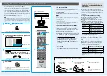
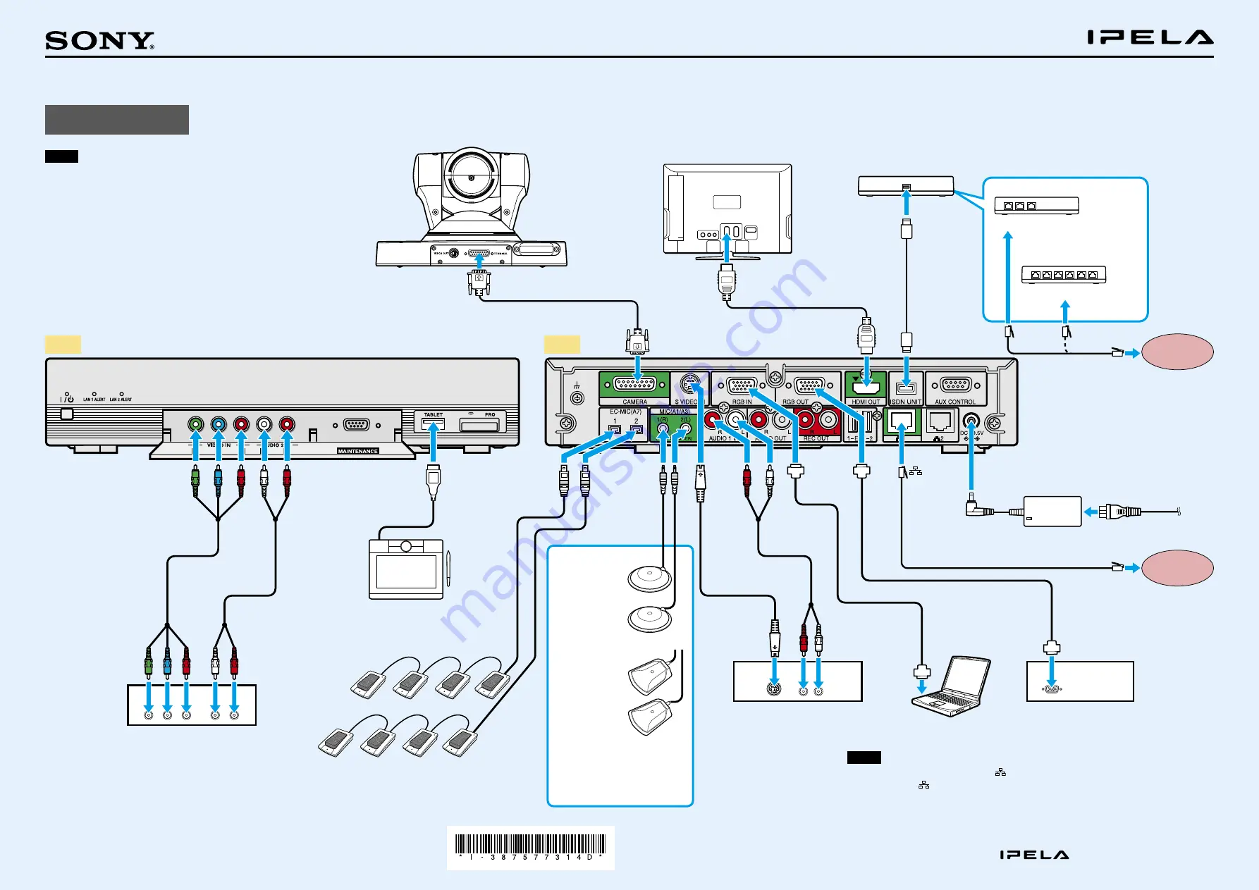
Let’s Connect
Notes
Be sure to turn off all the equipment before making any connections.
Do not connect/disconnect the camera cable, interface cable, or pen tablet with
the power on. Doing so may damage the Camera Unit, Communication System
or ISDN Unit.
For safety, do not connect the 100BASE-TX/10BASE-T connector to a network
that applies excess voltage via the 100BASE-TX/10BASE-T connector.
Used with the Camera Unit or ISDN Unit for the first time,
the Communication
System may automatically upgrade the software of the connected equipment.
Upgrade the software according to the message displayed on the monitor
screen. Be sure not to turn off the Communication System or disconnect the
cable during upgrading. Otherwise it may cause a malfunction of the system.
PCSA-CXG80 HD Camera
Unit (supplied with the
PCS-XG80)*
TV monitor**
ISDN Unit**
HDMI cable*
Interface
cable
(supplied
with the
ISDN Unit)
* Supplied
(However, the PCSA-CXG80 HD Camera Unit and the PCS-A1
microphones are not supplied with the PCS-XG80S system.)
** Not supplied
PCSA-B384S**
to ISDN 1 - 3
or
PCSA-B768S**
to ISDN 1 - 6
ISDN modular cable**
DC 19.5V
Power cord*
Computer
Projector, etc.
to RGB IN
UTP cable (category 5, straight)**
Connecting cable with the
D-sub 15 pin connectors**
Audio cable**
RGB IN
Connecting cable
with the D-sub 15 pin
connectors**
RGB
OUT
to
RGB
OUT
VCR, etc.
to S-video
output
to audio output
S-video cable**
AUDIO 1 IN
S VIDEO
IN
EC-MIC(A7)
1/2
MIC(A1/A3)
1(R)/2(L)
Connecting two
microphones enables pick-
up of the sound in stereo.
PCS-A1
Microphones
(supplied
with the
PCS-XG80)*
or
PCSA-A3
Microphones**
AUDIO 2 IN
VIDEO IN
YPbPr
Video cable**
Audio
cable**
to video
output
(YPbPr)
to audio output
HD player, etc.
PCSA-A7 Echo Canceling Microphones
(PCSA-A7P4: 4-piece set)**
Camera cable (supplied with
the HD Camera Unit)
LAN
Notes
Normally, connect the UTP cable to the
1 (LAN1) connector (indicated in green). If the UTP cable is
connected to the
2 (LAN2) connector, some of the functions of your system may be restricted.
For details, refer to the Operating Instructions supplied with the system.
The REC OUT jack is used to make an audio recording of a communication. This is not used during
regular communication.
ISDN line
Front
Rear
to a wall outlet
1
AC adaptor*
to TERMINAL
to HDMI IN
CAMERA
HDMI OUT
to TERMINAL
ISDN UNIT
TABLET
Pen tablet**
(Wacom BambooMTE450)