65
Connections for a Linear Editing System
Chap
ter
5
Conn
ec
ti
ons
a
nd Se
tt
ing
s
f
o
r Edit
in
g
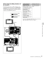
When using the editing functions of
the recorder
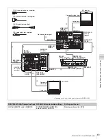
The following figure shows an HD cut editing system
comprising this unit as the player, and an HDW-M2000/
M2000P unit as the recorder. In this example, HD-SDI
video and audio signals are used, and control signals are
transferred via the REMOTE connector.
For details of HDW-M2000/M2000P settings, refer to the
HDW-M2000/M2000P Operation Manual.
75
Ω
REMOTE
AC IN
1/3
2/4
AUDIO
IN
VIDEO
IN Y/S-Y/CPST
R-Y/S-C
B-Y
REF.VIDEO
MONITOR
AUDIO
IN(SD/HD)
IN
IN
TC
OUT
1/2
3/4 1/2
3/4
OUT
AUDIO I/O (AES/EBU)
(SUPER)
CPST
HDV/DV
AUDIO
OUT
1/3
2/4
VIDEO OUT
Y/CPST
Pr/R-Y/S-C
Pb/B-Y/S-Y
OUT1
IN(SD/HD)
SDI
OUT2 SDI
OUT1
OUT2
HD SDI
HD SDI
OUT1,OUT2
HD SDI
OUT1,OUT2
HDSDI
INPUT
REMOTE
REMOTE 1-IN(9P)
HDSDI
OUTPUT 3
(SUPER)
REF.VIDEO IN
(SD/HD)
REF.VIDEO IN
(SD/HD)
REF VIDEO
INPUT
HD monitor
2
9-pin remote cable (not supplied)
1
75
Ω
coaxial cable (not supplied)
HD-SDI input
HVR-1500A
(this unit as player)
Reference video
signal
HDW-M2000/
M2000P (recorder)
HD-SDI input
HD monitor
2
1
1
1
1
1
HDW-M2000/M2000P
(recorder) settings
Settings on this unit
REMOTE 1(9P) button: lit
Remote control switch:
9PIN
REF.VIDEO INPUT connector
75
Ω
termination switch: ON
Audio selection function
switching button
INPUT button: HDSDI
Function menu HOME >F1
(VID. IN): SDI
Function menu page 1 >F1
(TCG): INT
Function menu page 1 >F2
(PR/RGN): PRESET
Function menu page 1 >F3
(RUN): FREE

