background image

18

GB

C:\Documents and 
Settings\pc13\Desktop\J9052001_2662269111DDW780_GB\2662269111\GB03CON_HT-
DDW780_CEL.fm

masterpage: Left

HT-DDW780

2-662-269-

11

 (1)

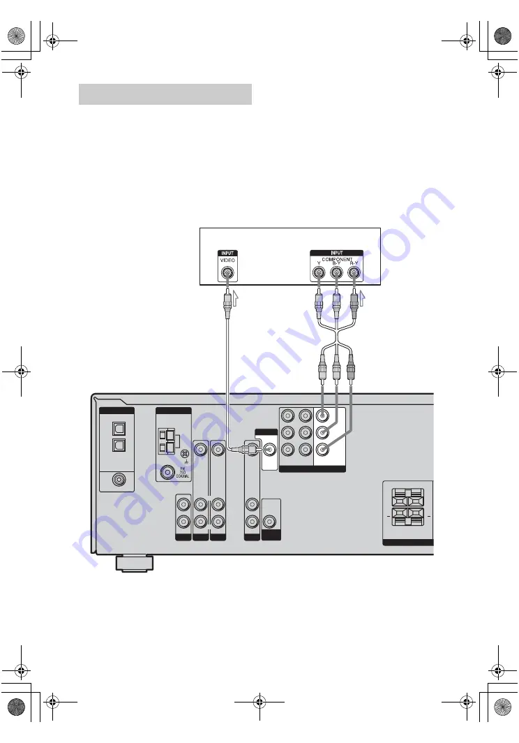
The image from a visual component connected 
to this receiver can be displayed on a TV 
screen.
It is not necessary to connect all the cables. 
Connect video cords according to the jacks of 
your components.

Notes

• Connect image display components such as a TV 

monitor or a projector to the MONITOR OUT jack 
on the receiver.

• Turn on the receiver when the video and audio of a 

playback component are being output to a TV via 
the receiver. If the power supply of the receiver is 
not turned on, neither video nor audio is 
transmitted.

Tip

You can watch the selected input image when you 
connect the MONITOR OUT jack to a TV monitor.

Hooking up a TV monitor

DVD IN

SA-CD/CD

AUDIO IN

DVD

AUDIO IN

VIDEO 2

AUDIO IN

VIDEO IN

VIDEO IN

DIGITAL

OPTICAL

VIDEO 2

IN

VIDEO 1

IN

COAXIAL

AM

ANTENNA

SURROUND

SPEAKER

L

R

L

R

+

+

R

L

R

L

R

L

AUDIO

OUT

VIDEO 1

COMPONENT VIDEO

AUDIO IN

VIDEO IN

DVD

IN

VIDEO 2

IN

MONITOR

OUT

SUB

WOOFER

VIDEO OUT

MONITOR

Y

P

B

/C

B

/B–Y

P

R

/C

R

/R–Y

TV monitor

B

A

A

Video cord (not supplied)

B

Component video cord (not supplied)

GB01COV_HT-DDW780_CEL.book  Page 18  Friday, January 20, 2006  11:32 AM

Summary of Contents for HT-DDW780

Page 1: ... Settings pc13 Desktop J9052001_2662269111DDW780_GB 2662269111 GB01COV_HT DDW780_CEL fm masterpage Right 2006 Sony Corporation 2 662 269 11 1 Home Theatre System Operating Instructions HT DDW780 GB01COV_HT DDW780_CEL book Page 1 Friday January 20 2006 11 32 AM ...

Page 2: ...speakers SS SRP680 Sub woofer SA WP780 This receiver incorporates Dolby Digital and Pro Logic Surround and the DTS Digital Surround System Manufactured under license from Dolby Laboratories Dolby Pro Logic and the double D symbol are trademarks of Dolby Laboratories DTS and DTS Digital Surround are registered trademarks of Digital Theater Systems Inc WARNING Do not install the appliance in a confi...

Page 3: ...ttings for the tuner TUNER menu 38 Settings for the audio AUDIO menu 38 Settings for the system SYSTEM menu 39 Calibrating the appropriate settings automatically A CAL menu 41 Enjoying Surround Sound Enjoying Dolby Digital and DTS Surround sound AUTO FORMAT DIRECT 42 Selecting a pre programmed sound field 43 Using only the front speakers and sub woofer 2CH STEREO 45 Resetting sound fields to the i...

Page 4: ...s of the display D Remote sensor Receives signals from remote commander E Display The current status of the selected component or a list of selectable items appears here page 6 F 2CH Press to select 2CH STEREO mode page 39 45 G A F D Press to select A F D mode page 42 Name Function H MOVIE MUSIC Press to select sound fields MOVIE MUSIC page 43 I MASTER VOLUME Turn to adjust the volume level of all...

Page 5: ...the buttons to select the component you want to use O PRESET TUNING Press to select a preset station P TUNING Press to scan a station Q MEMORY Press to store a station R FM MODE Press to select FM monaural or stereo reception S PHONES jack Connects to a headphone page 58 T AUTO CAL MIC jack Connects to the supplied ECM AC2 optimizer microphone for the Auto Calibration function page 25 continued GB...

Page 6: ...OGIC II lights up when the Pro Logic II Movie Music decoder is activated Note Dolby Pro Logic and Dolby Pro Logic II decoding do not function for DTS format signals Name Function F DTS Lights up when DTS signals are input Note When playing a DTS format disc be sure that you have made digital connections and that INPUT MODE is not set to ANALOG page 52 G MEMORY Lights up when a memory function such...

Page 7: ... C SL SR S The letters L C R etc indicate the channels being played back The boxes around the letters vary to show how the receiver downmixes the source sound Front Left Front Right Center monaural Surround Left Surround Right Surround monaural or the surround components obtained by Pro Logic processing Example Recording format Front Surround Dolby Digital 3 2 1 Sound Field A F D AUTO L C R SL SR ...

Page 8: ...etc The COAXIAL jack provides a better quality of loud sound page 19 21 COAXIAL IN jack B ANTENNA section FM ANTENNA Connects to the FM wire antenna supplied with this receiver page 23 AM ANTENNA Connects to the AM loop antenna supplied with this receiver page 23 C VIDEO AUDIO INPUT OUTPUT section AUDIO IN OUT jack Connects the video and audio jacks of a VCR or a DVD player page 16 18 19 20 21 22 ...

Page 9: ...to operate If you press 1 B at the same time it will turn off the receiver and other components SYSTEM STANDBY Note The function of the AV 1 switch changes automatically each time you press the input buttons C B TV 1 Press TV 1 and TV P at the same time to turn the TV on or off 1 Press to turn the receiver on or off To turn off all components press 1 and AV 1 A at the same time SYSTEM STANDBY C In...

Page 10: ...the menus of the VCR DVD player or satellite tuner on the TV screen Then use the control buttons to perform menu operations Name Function O Press to skips tracks of the CD player DVD player or tape deck REPLAY ADVANCE Press to replay the previous scene or fast forward the current scene of the VCR or DVD player m M Press to search tracks in the forward backward direction of the DVD player fastforwa...

Page 11: ...d TV P at the same time to select the channel entry mode either one or two digits of the TV 10 x Press to select track numbers over 10 of the VCR satellite tuner or CD player channel numbers of the Digital CATV terminal CLEAR Press to clear a mistake when you press the incorrect numeric buttons return to continuous playback etc of the satellite tuner or DVD player U Numeric buttons number 5 Press ...

Page 12: ... woofer Tip Since the sub woofer does not emit highly directional signals you can place it wherever you want Before you install the speakers and sub woofer be sure to attach the supplied foot pads to prevent vibration or movement as shown in the illustration below For greater flexibility in positioning the speakers use the optional WS FV11 or WS FV10D speaker stand available only in certain countr...

Page 13: ...the wall material and strength As a plaster board wall is especially fragile attach the screws securely to a beam and fasten them to the wall Install the speakers on a vertical and flat wall where reinforcement is applied Contact a screw shop or installer regarding the wall material or screws to be used Sony is not responsible for accident or damage caused by improper installation insufficient wal...

Page 14: ...s The center speaker and sub woofer do not have the character on the speaker label For details on the speaker type see page 2 L R L R R L VIDEO 1 COMPONENT VIDEO AUDIO IN VIDEO IN VIDEO OUT DVD IN VIDEO 2 IN MONITOR OUT MONITOR Y PB CB B Y PR CR R Y SUB WOOFER L R CENTER L R AUDIO OUT SPEAKERS SURROUND FRONT F B A E D C ASpeaker cords short supplied BSpeaker cords long supplied CMonaural audio cor...

Page 15: ...k up your components to this receiver After hooking up all your components proceed to 4 Connecting the antennas page 23 The sound quality depends on the connecting jack Refer to the illustration that follows Select the connection according to the jacks of your components How to hook up your components Audio input jack to be connected Digital Analog High quality sound GB01COV_HT DDW780_CEL book Pag...

Page 16: ...er Connecting audio components DVD IN SA CD CD AUDIO IN DVD AUDIO IN VIDEO 2 AUDIO IN VIDEO IN VIDEO IN DIGITAL OPTICAL VIDEO 2 IN VIDEO 1 IN COAXIAL AM ANTENNA SURROUND SPEAKER L R L R R L R L R L AUDIO OUT VIDEO 1 COMPONENT VIDEO AUDIO IN VIDEO IN VIDEO OUT DVD IN VIDEO 2 IN MONITOR OUT SUB WOOFER MONITOR Y PB CB B Y PR CR R Y Super Audio CD player CD player A AAudio cord not supplied GB01COV_HT...

Page 17: ...on according to the jacks on your components Notes Connect image display components such as a TV monitor or a projector to the MONITOR OUT jack on the receiver Turn on the receiver when the video and audio of a playback component are being output to a TV through the receiver If the power supply of the receiver is not on neither video nor audio is transmitted How to hook up your components Componen...

Page 18: ... playback component are being output to a TV via the receiver If the power supply of the receiver is not turned on neither video nor audio is transmitted Tip You can watch the selected input image when you connect the MONITOR OUT jack to a TV monitor Hooking up a TV monitor DVD IN SA CD CD AUDIO IN DVD AUDIO IN VIDEO 2 AUDIO IN VIDEO IN VIDEO IN DIGITAL OPTICAL VIDEO 2 IN VIDEO 1 IN COAXIAL AM ANT...

Page 19: ... the DVD player When connecting optical digital cords insert the plugs straight in until they click into place Do not bend or tie optical digital cords Tip All the digital audio jacks are compatible with 32 kHz 44 1 kHz 48 kHz and 96 kHz sampling frequencies Hooking up a DVD player DVD recorder SA CD CD AUDIO IN DVD AUDIO IN VIDEO 2 AUDIO IN VIDEO IN VIDEO IN AM ANTENNA SURROUND SPEAKER L R L R R ...

Page 20: ...e receiver s display For details see Naming inputs page 53 You cannot do recording on the DVD recorder via this receiver For details refer to the operating instructions supplied with the DVD recorder DVD IN SA CD CD AUDIO IN DVD AUDIO IN VIDEO 2 AUDIO IN VIDEO IN VIDEO IN DIGITAL OPTICAL VIDEO 2 IN VIDEO 1 IN COAXIAL AM ANTENNA SURROUND SPEAKER L R L R R L R L R L AUDIO OUT VIDEO 1 COMPONENT VIDEO...

Page 21: ...e optical digital cords Tip All the digital audio jacks are compatible with 32 kHz 44 1 kHz 48 kHz and 96 kHz sampling frequencies Hooking up a satellite tuner SA CD CD AUDIO IN DVD AUDIO IN VIDEO 2 AUDIO IN VIDEO IN VIDEO IN AM ANTENNA SURROUND SPEAKER L R L R R L R L R L AUDIO OUT VIDEO 1 AUDIO IN VIDEO IN VIDEO OUT SUB WOOFER MONITOR DVD IN DIGITAL OPTICAL VIDEO 2 IN VIDEO 1 IN COAXIAL DVD IN V...

Page 22: ...efer to the operating instructions supplied with the VCR Hooking up a VCR DVD IN SA CD CD AUDIO IN DVD AUDIO IN VIDEO 2 AUDIO IN VIDEO IN VIDEO IN DIGITAL OPTICAL VIDEO 2 IN VIDEO 1 IN COAXIAL AM ANTENNA SURROUND SPEAKE L R L R R L R L R L AUDIO OUT VIDEO 1 COMPONENT VIDEO AUDIO IN VIDEO IN VIDEO OUT DVD IN VIDEO 2 IN MONITOR OUT SUB WOOFER MONITOR Y PB CB B Y PR CR R Y VCR A AAudio video cord not...

Page 23: ...nna away from the receiver and other components Be sure to fully extend the FM wire antenna After connecting the FM wire antenna keep it as horizontal as possible DVD IN SA CD CD AUDIO IN DVD AUDIO IN VIDEO 2 AUDIO IN VIDEO IN VIDEO IN DIGITAL OPTICAL VIDEO 2 IN VIDEO 1 IN COAXIAL AM ANTENNA SURROUND SPEAKER L R L R R L R L R L AUDIO OUT VIDEO 1 COMPONENT VIDEO AUDIO IN VIDEO IN VIDEO OUT DVD IN V...

Page 24: ...eiver 2 Hold down 1 for 5 seconds PUSH and ENTER appears on the display alternately 3 Press ENTER After CLEARING appears on the display for a while CLEARED appears The following items are reset to their factory settings All settings in the LEVEL TONE SUR TUNER AUDIO and SYSTEM menus The sound field memorized for each input and preset station All sound field parameters All preset stations All index...

Page 25: ...ries with new ones 6 Calibrating the appropriate settings automatically AUTO CALIBRATION This receiver is equipped with D C A C Digital Cinema Auto Calibration Technology which allows you to perform Automatic Calibration as follows Check the connection between each speaker and the receiver Adjust the speaker level Measure the distance of each speaker to your listening position You can also adjust ...

Page 26: ... The measurement process will take a few minutes to complete Tips When Auto Calibration starts Stand some distance away from the speakers and the listening position to avoid measurement failure This is because test signals are output from the speakers during measurement Avoid making noise to get a more accurate measurement The Auto Calibration function will be canceled when you do the following du...

Page 27: ... You can also change the settings manually To change the settings manually 1 Record down the warning code 2 Press the control button You can also use ENTER on the receiver 3 Press 1 to turn off the receiver 4 Follow the solution provided in the Warning code and solution below 5 Turn on the receiver and perform Auto Calibration again page 26 Warning code and solution Error and warning codes Error c...

Page 28: ...select T TONE You can also use U or u on the receiver Warning code Explanation Solution WARN 63 The surround left speaker level is out of range Reposition your surround left speaker e WARN 64 The surround right speaker level is out of range Reposition your surround right speaker f WARN 70 The front speakers distance are out of range Reposition your front speakers c WARN 72 The center speaker dista...

Page 29: ...ASTER VOLUME on the receiver The adjusted value are shown on the display during adjustment To turn off the test tone Repeat steps 1 to 5 above to select T TONE N Selecting a component 1 Press the input button to select a component The selected input appears on the display 2 Turn on the component and start playback Playback Selected input Display Components that can be played back VIDEO 1 or VIDEO ...

Page 30: ...urn off the receiver To avoid damaging your speakers Before you turn off the receiver be sure to turn down the volume level To listen to the sub woofer Be sure to use the buttons on the sub woofer for this operation 1 Press POWER The POWER indicator lights up 2 Turn LEVEL to adjust the volume Set the volume level to suit your preference accordingly to the selected input as slight adjustments may e...

Page 31: ...UME INPUT MODE DISPLAY DIMMER 2CH A F D MOVIE MUSIC 1 2 3 5 5 3 Notes The operation is described for a Sony Super Audio CD player Refer to the operating instructions supplied with the Super Audio CD player or CD player Tips You can select the sound field to suit the music Refer to page 43 for details Recommended sound fields Classical HALL Jazz JAZZ Live concert CONCERT You can listen to the sound...

Page 32: ... instructions supplied with the TV and DVD player Check the following if you cannot listen to multi channel sound Be sure this receiver is connected to the DVD player via a digital connection Be sure the digital audio output of the DVD player is set up properly Tips Select the sound format of the disc to be played if necessary You can select the sound field to suit the movie music Refer to page 43...

Page 33: ...er 5 Press the control button or control button b to enter the parameter You can also use ENTER or i on the receiver 6 Press control button V v repeatedly to select the setting you want You can also use U or u on the receiver The setting is applied automatically To return to the previous display Press control button B You can also use I on the receiver To exit the menu Press AMP MENU Note Some par...

Page 34: ...UR L 0 dB Surround right speaker level SR LVL SUR R 10 dB to SUR R 10 dB 1 dB step SUR R 0 dB Sub woofer level SW LVL SW 10 dB to SW 10 dB 1 dB step SW 0 dB Dynamic range compressora D RANGE COMP OFF COMP STD COMP MAX COMP OFF TONE 37 2 TONE Front speaker bass level BASS LVL BASS 6 dB to BASS 6 dB 1 dB step BASS 0 dB Front speaker treble level TRE LVL TRE 6 dB to TRE 6 dB 1 dB step TRE 0 dB SUR 37...

Page 35: ...a A V SYNC A V SYNC Y A V SYNC N A V SYNC N Naming inputsa NAME IN SYSTEM 39 6 SYSTEM Front speakers distancea FRT DIST DIST 1 0 m to DIST 7 0 m 0 1 m step DIST 3 0 m Center speaker distancea CNT DIST DIST 1 0 m to DIST 7 0 m 0 1 m step DIST 3 0 m Surround left speaker distancea SL DIST DIST 1 0 m to DIST 7 0 m 0 1 m step DIST 3 0 m Surround right speaker distancea SR DIST DIST 1 0 m to DIST 7 0 m...

Page 36: ...ft speaker level x SR LVL Surround right speaker level x SW LVL Sub woofer level x D RANGE Dynamic range compressor Lets you compress the dynamic range of the sound track This may be useful when you want to watch movies at low volumes late at night Dynamic range compression is possible with Dolby Digital sources only COMP OFF The dynamic range is not compressed COMP STD The dynamic range is compre...

Page 37: ...re Select 3 SUR in the amplifier menus For details on adjusting the parameters see Navigating through menus page 33 and Overview of the menus page 34 SUR menu parameters x S F SELCT Sound field selection Lets you select the sound field you want For details see Enjoying Surround Sound page 42 Note The receiver lets you apply the last selected sound field to an input whenever it is selected Sound Fi...

Page 38: ... stations For details see Naming preset stations page 50 Settings for the audio AUDIO menu You can use the AUDIO menu to make settings for the audio to suit your preference Select 5 AUDIO in the amplifier menus For details on adjusting the parameters see Navigating through menus page 33 and Overview of the menus page 34 AUDIO menu parameters x DEC PRI Digital audio input decoding priority Lets you...

Page 39: ...a projector This parameter is valid only when you use a sound field selected with the 2CH or A F D buttons This parameter is not valid when PCM 96 kHz or DTS 2048 signals are input x NAME IN Naming inputs Lets you set the name of inputs For details see Naming inputs page 53 Settings for the system SYSTEM menu You can use the SYSTEM menu to set the distance of the speakers connected to this system ...

Page 40: ...e incorrect speaker placement is not conducive to the enjoyment of surround sound Please note that setting the speaker distance closer than the actual location of the speakers will cause a delay in the output of the sound from that speaker In other words the speaker will sound like it is further away For example setting the center speaker distance 1 2 meters closer than the actual speaker position...

Page 41: ... such as wall reflections and you may obtain better results using BEHD HI if your speakers are located high above the listening position even if they are located to the immediate left and right Therefore although it may result in a setting contrary to the above explanation we recommend that you playback multi channel surround encoded software and select the setting that provides a good sense of sp...

Page 42: ...F D AUTO A F D AUTO Detecting automatically Performs the sound as it was recorded encoded without adding any surround effects However this receiver will generate a low frequency signal for output to the sub woofer when there is no LFE signals Dolby Pro Logic PRO LOGIC DOLBY PL 4 channel Performs Dolby Pro Logic decoding The source recorded in 2 channel format is decoded into 4 1 channels Dolby Pro...

Page 43: ...d characteristics of the Sony Pictures Entertainment Kim Novak Theater cinema production studio This mode is ideal for watching science fiction or action movies with lots of sound effects CINEMA STUDIO EX C DCS C ST EX C Reproduces the sound characteristics of the Sony Pictures Entertainment scoring stage This mode is ideal for watching musicals or films where orchestra music is featured in the so...

Page 44: ...g three elements Virtual Multi Dimension Creates 5 sets of virtual speakers from a single pair of actual surround speakers Screen Depth Matching Creates the sensation that the sound is coming from inside the screen like in theaters Cinema Studio Reverberation Reproduces the type of reverberation found in theaters The CINEMA STUDIO EX modes integrate these three elements simultaneously Notes The ef...

Page 45: ...input the receiver s bass redirection circuitry will be activated The front channel bass frequencies will be output from the sub woofer Press 2CH Resetting sound fields to the initial settings Be sure to use the buttons on the receiver for this operation 1 Press 1 to turn off the receiver 2 While holding down 2CH press 1 S F CLR appears on the display and all sound fields are reset to their initia...

Page 46: ...ral audio so that the sound will be less distorted Press FM MODE repeatedly until the MONO indicator lights up on the display To return to stereo mode press FM MODE repeatedly until the MONO indicator on the display do not light up Enter the frequency of a station directly by using the numeric buttons 1 Press TUNER repeatedly to select the FM or AM band You can also use FM or AM on the receiver 2 ...

Page 47: ...ns one by one see Presetting radio stations page 48 Be sure to use the buttons on the receiver for this operation 1 Press 1 to turn off the receiver 2 Hold down MEMORY and press 1 to turn the receiver back on AUTO BETICAL SELECT appears on the display and the receiver scans and stores all the FM and FM RDS stations in the broadcast area For RDS stations the tuner first checks for stations broadcas...

Page 48: ... again Presetting radio stations You can preset up to 30 FM stations and 30 AM stations Then you can easily tune in the stations you often listen to 1 Press TUNER repeatedly to select the FM or AM band You can also use FM or AM on the receiver 2 Tune in the station that you want to preset using Automatic Tuning page 46 or Direct Tuning page 46 Switch the FM reception mode if necessary page 46 Pres...

Page 49: ... station 1 Press TUNER repeatedly to select the FM or AM band You can also use FM or AM on the receiver 2 Press PRESET or PRESET repeatedly to select the preset station you want You can also use PRESET TUNING or PRESET TUNING on the receiver Each time you press the button you can select a preset station as follows You can also press the numeric buttons to select the preset station you want Then pr...

Page 50: ...n index name 1 Use control button V v B b to create an index name You can also use U or u and I or i on the receiver Press control button V v to select a character then press control button B b to move the cursor to the next position If you made a mistake Press control button B b until the character you want to change flashes then press control button V v to select the correct character Tip You ca...

Page 51: ...edly on the receiver Each time you press the button RDS information on the display changes cyclically as follows Program Service name t Frequency t Program Type indicationa t Radio Text indicationb t Current Time indication in 24 hour system mode t Sound field currently applied a Type of program being broadcast b Text messages sent by the RDS station Notes If there is an emergency announcement by ...

Page 52: ...e input VARIED Other types of programs such as celebrity interviews panel games and comedy POP M Popular music programs ROCK M Rock music programs EASY M Easy Listening LIGHT M Instrumental vocal and choral music CLASSICS Performances of major orchestras chamber music opera etc OTHER M Music that does not fit into any categories above such as Rhythm Blues and Reggae WEATHER Weather information FIN...

Page 53: ...r flashes and you can select a character Follow the procedure given in To create an index name page 50 To return to the previous display Press control button B You can also use I on the receiver Changing the display You can check the sound field etc by changing the information on the display Be sure to use the button on the receiver for this operation Press DISPLAY repeatedly Each time you press t...

Page 54: ...ns off press SLEEP The remaining time appears on the display If you press SLEEP again the sleep timer will be canceled Changing button assignments You can change the factory settings of the input buttons to suit the components in your system For example if you connect a DVD recorder to the DVD jacks on the receiver you can set the DVD button on this remote to control the DVD recorder 1 Hold down t...

Page 55: ...livered than with Dolby surround x Dolby Pro Logic II This technology converts 2ch stereo recorded audio into 5 1ch for playback There is a MOVIE mode for movies and MUSIC mode for stereo sources such as music Old movies encoded in the traditional stereo format can be enhanced with 5 1ch surround sound x Dolby Surround Dolby Pro Logic Audio processing technology developed by Dolby Laboratories Inc...

Page 56: ... On power sources Before operating the receiver check that the operating voltage is identical with your local power supply The operating voltage is indicated on the nameplate on the back of the receiver The unit is not disconnected from the AC power source mains as long as it is connected to the wall outlet even if the unit itself has been turned off If you are not going to use the receiver for a ...

Page 57: ...etc as staining or discoloration of the surface may result On operation Before connecting other components be sure to turn off and unplug the receiver If you encounter color irregularity on a nearby TV screen The front and center speakers and the sub woofer are magnetically shielded to allow it to be installed near a TV set However color irregularities may still be observed on certain types of TV ...

Page 58: ...ct component on the receiver There is no sound from one of the front speakers Connect a pair of headphones to the PHONES jack to verify that sound is output from the headphones If only one channel is output from the headphones the component may not be connected to the receiver correctly Check that all the cords are fully inserted into the jacks on both the receiver and the component If both channe...

Page 59: ...gital input jacks of this receiver check the audio setting settings for the audio output of the connected component The FM reception is poor Use a 75 ohm coaxial cable not supplied to connect the receiver to an outdoor FM antenna as shown below If you connect the receiver to an outdoor antenna ground it against lightning To prevent a gas explosion do not connect the ground wire to a gas pipe Radio...

Page 60: ...ny problem persists consult your nearest Sony dealer If an error message appears while you perform Auto Calibration see Error and warning codes page 27 to solve the problem DEC EROR Appears when a signal the receiver cannot decode ex DTS CD is input and DEC PRI on the AUDIO menu is set to DEC PCM Set it to DEC AUTO page 35 PROTECT Irregular current is output from the speakers The receiver will aut...

Page 61: ...2 Depending on the sound field settings and the source there may be no sound output Inputs Analog Inputs Digital Outputs Analog Reproduction frequency range 28 20 000 Hz Tone FM tuner section Tuning range 87 5 108 0 MHz Antenna FM wire antenna Antenna terminals 75 ohms unbalanced Intermediate Frequency 10 7 MHz AM tuner section Tuning range Models of area code CEL CEK SP AU With 9 kHz tuning scale...

Page 62: ...one type Enclosure type Acoustically loaded bass reflex RMS output 150 W 6 ohms 100 Hz THD 10 Music Power 190 W Input LINE IN input pin jacks Power requirements Power consumption 80 W Dimensions w h d Approx 270 331 380mm including front panel Mass Approx 8 3 kg Supplied accessories FM wire antenna 1 AM loop antenna 1 Speaker cords long 2 Speaker cords short 3 Coaxial digital cord 1 Monaural audio...

Page 63: ...ooking up 19 playback 32 E Error messages 60 I Initial setup 24 INPUT MODE 52 M Menu A CAL 41 AUDIO 38 LEVEL 36 SUR 37 SYSTEM 39 TONE 37 TUNER 38 Muting 30 N Naming 50 R RDS 51 S Satellite tuner hooking up 21 Selecting component 29 sound field 43 Sleep Timer 54 Sound fields resetting 45 selecting 43 Speakers connecting 14 installing 12 Super Audio CD player connecting 16 playback 31 Supplied acces...

Page 64: ...ts and Settings pc13 Desktop J9052001_2662269111DDW780_GB 2662269111 GB07BKC_HT DDW780_CEL fm Sony Corporation Printed in Malaysia model name1 STR DG500 2 662 269 11 1 GB01COV_HT DDW780_CEL book Page 64 Friday January 20 2006 11 32 AM ...

Reviews: