background image

83

Menu Contents


Chap

te

r 7
  

Men

u

s

AUDIO CONTROL [Audio]: Settings related to audio 
control 

Description of settings

JOG CONTROL [> Jog ctrl]: 

Select whether to adjust the 

audio playback speed during slow playback.

Note 

This setting is invalid when playing back in HDV format.

OFF [>> OFF]: 

Do not adjust the audio playback speed.

*

ON [>> ON]: 

Adjust the audio playback speed.

MUTING IN SHTL [> Shutl mute]: 

Set the audio muting 

conditions during shuttle playback.

Note 

This setting is invalid when playing back in HDV format.

*

OFF [>> OFF]: 

Not suppressed.

CUEUP or PREROLL [>> CUEUP]:

 Suppressed during cue-

up or preroll operations.

FULL [>> FULL]:

 Suppressed in shuttle mode.

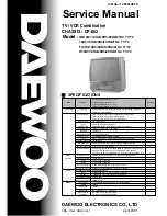
AUDIO EDIT [> Audio edit]:

 Specify the type of editing for 

audio signals.

Note 

This setting is invalid for the HDV format.

*

CUT EDIT [>> Cut edit]: 

Cut editing (Discontinuity in audio 

signal may result at the editing point, causing noise during 
playback.)

FADE IN/OUT [>> Fade]:

 Fade in and fade out

DV PB ATT [> DV PB ATT]:

 When playing back a tape 

recorded in consumer DV format, select whether to 
attenuate the audio output level.

OFF [>> OFF]: 

Do not attenuate.

*

ON [>> ON]: 

Attenuate.

Note 

This setting is valid only when the recording format setting is 
DVCAM. This is not valid for DV(SP) format.

INTERFACE SELECT [Interface]: Settings related to 
external interfaces

Description of settings

VIDEO OUTPUT [> Video Out]: 

Select the format of analog 

video signals to be output from the three VIDEO OUT 
connectors).

*

COMPOSITE&S-VIDEO [>> Compst&S]:

 Set to S-Y, S-C 

output and composite output.

COMPONENT (SD) [>> Compnt SD]:

 Set to component Y/R-

Y/B-Y (SD) output.

COMPONENT (HD) [>> Compnt HD]:

 Set to component Y/Pr/

Pb (HD) output.

AUDIO OUTPUT [> Audio Out]: 

Select the channels for 

audio output from the AUDIO OUT 1/3 and 2/4 
connectors.

*

1/2 CH [>> 1/2CH]:

 Output channel 1 to the AUDIO OUT 1/3 

connector and channel 2 to the AUDIO OUT 2/4 connector.

3/4 CH [>> 3/4CH]: 

Output channel 3 to the AUDIO OUT 1/3 

connector and channel 4 to the AUDIO OUT 2/4 connector.

i.LINK FORMAT [> i.Link Fmt]:

 Select whether the i.LINK 

output format is automatically determined, or whether it is 
switched according to the i.LINK input selection.

Note 

Since the i.LINK stream is different for HDV or DV/DVCAM, 
switching causes a bus reset on the i.LINK interface, which 
may cause a problem with some connected nonlinear editors. 
In such cases, set this item to i.LINK INPUT, and select the 
i.LINK input format to match that to be used.

* AUTO [>> AUTO]:

 The i.LINK output format is automatically 

determined as follows.

During playback:

 Switched automatically to DV/DVCAM 

or HDV according to the format in which the tape is 
recorded.

During recording or EE mode:

 HDV format when the 

i.LINK input is HDV, and DV/DVCAM format when 
another format is selected.

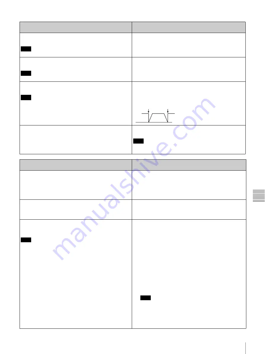
i.LINK INPUT [>> i.Link in]:

The i.LINK output format is 

switched as follows, according to the i.LINK input selection.

For DV/DVCAM input selection:

 Fixed at DV/DVCAM 

format. During HDV tape playback, output converted to 
DV or DVCAM according to the DV recording format. 
(i.LINK OUTPUT menu item setting is invalid).

For HDV input selection:

 The i.LINK output is always an 

HDV signal.

Note

In this case, DV/DVCAM tape playback is not possible.

For SD input selection other than i.LINK:

 As for AUTO, 

the playback format is automatically switched to DV/
DVCAM or HDV according to the format recorded on 
the tape, and the setting of the i.LINK OUTPUT menu 
item.

IN

OUT

Summary of Contents for HDV HVR-1500

Page 1: ...ly and retain it for future reference HVR 1500 2006 Sony Corporation Sony Corporation Printed in China The supplied CD ROM includes Operating Instructions for the HVR 1500 digital HD videocassette recorder English Japanese French German Italian and Spanish versions in PDF format For more details see page 11 Using the CD ROM Manual ...

Page 2: ...MUST BE EARTHED CAUTION The apparatus shall not be exposed to dripping or splashing No objects filled with liquids such as vases shall be placed on the apparatus The unit is not disconnected from the AC power source mains as long as it is connected to the wall outlet even if the unit itself has been turned off When installing the installation space must be secured in consideration of the ventilati...

Page 3: ...tdoors E4 controlled EMC environment ex TV studio The manufacturer of this product is Sony Corporation 1 7 1 Konan Minato ku Tokyo Japan The Authorized Representative for EMC and product safety is Sony Deutschland GmbH Hedelfinger Strasse 61 70327 Stuttgart Germany For any service or guarantee matters please refer to the addresses given in separate service or guarantee documents For the customers ...

Page 4: ...eiten gefüllten Gegenstände z B Vasen darauf abgestellt werden ACHTUNG Solange das Netzkabel an eine Netzsteckdose angeschlossen ist bleibt das Gerät auch im ausgeschalteten Zustand mit dem Strommetz verbunden WICHTIG Das Namensschild befindet sich auf der Unterseite des Gerätes WARNUNG 1 Verwenden Sie ein geprüftes Netzkabel 3 adriges Stromkabel einen geprüften Geräteanschluss einen geprüften Ste...

Page 5: ...7 Connecting an External Monitor 28 To View Video 28 To View HD Video 28 Superimposed Text Information 29 To Turn Superimposed Text on and off 29 Adjusting the Text Display 29 Information Displayed 29 Displaying Supplementary Status Information 30 Time Data Handled by This Unit 32 Displaying the Time Data and Operating Mode 32 Displaying on the Monitor Screen 32 Recording Formats and Input Output ...

Page 6: ...Synchronizing the Internal Timecode Generator to an External Timecode External Synchronization 53 Outputting Timecode 54 Timecode Output During Playback 54 Timecode Output During Recording and in E E Mode 54 Chapter 5 Connections and Settings for Editing Connection Using i LINK 55 Use in a Nonlinear Editing System AV C Connection 55 Using in a Cut Editing System 56 Connections for a Linear Editing...

Page 7: ...ANCED Menu Items 88 Changing the Settings of ENHANCED Menu Items 88 Returning Menu Settings to Their Factory Default Settings 88 Assigning a Function to the ASSIGN Button 89 Appendix Important Notes on Operation 91 Note on faulty pixels on the LCD panel 91 Condensation 91 Periodical Maintenance 92 Digital hours meter 92 Head Cleaning 94 Troubleshooting 95 Alarm Messages 96 Error Messages 98 About ...

Page 8: ...adopted for satellite and terrestrial digital HDTV broadcasting and Blu ray disc Within the HDV format this unit provides for an effective 1080 interlaced scan lines in HDV 1080 60i and HDV 1080 50i formats image size 1440 1080 pixels The video recording bitrate is approximately 25 Mbps The digital interface is i LINK allowing connection to HDV supporting peripherals High performance down conversi...

Page 9: ...can readily be used as a viewer for example at broadcasting stations and aboard outside broadcast vans without requiring any option boards Inputting analog video and audio signals requires the optional HVBK 1505 Analog Input Board Other Features Support for both 1080 525 60i NTSC and 1080 625 50i PAL formats This unit supports both 60i and 50i formats You can switch between these signal formats wi...

Page 10: ... functions Self diagnostic alarm function This function automatically detects setup and connection errors operation faults and other problems It also displays a description of the problem its cause and the recommended response on the monitor screen or time counter display Digital hours meter The digital hours meter functions include four kinds of tally operations for operating hours head drum usag...

Page 11: ...d in the United States and or other countries Reading the CD ROM Manual To read the operating instructions contained on the CD ROM do the following 1 Insert the CD ROM in your CD ROM drive A cover page appears automatically in your browser If it does not appear automatically in the browser double click on the index htm file on the CD ROM 2 Select and click on the operating instructions that you wa...

Page 12: ...SIGN CH1 OVER REPEAT 60i 720 30p 720 60p 01 23 45 15 48K PRESET VARIABLE REC PB LEVEL MONITOR SELECT COUNTER SELECT PHONES CONTROL S REW PLAY F FWD i LINK 1 2 VIDEO 3 A B CH1 1 2 4 CH2 3 4 REC STOP EJECT LOCAL i LINK HDV DVCAM DV 9PIN INPUT SELECT REC PB LEVEL POWER DISPLAY MENU RESET NO SET YES TC PRESET ASSIGN 0 12 20 30 40 60 TC VITC OVER CH2 EDIT MODE CH1 OVER REPEAT 60i 720 30p 720 60p 01 23 ...

Page 13: ... Once you assign a menu item you can recall the menu by simply pressing the ASSIGN button On how to assign a menu item see Assigning a Function to the ASSIGN Button page 89 k MENU button Press this button to display the menu on the LCD monitor and the monitor screen Press it again to exit the menu display On how to use the menu see Chapter 7 Menus page 70 l TC timecode PRESET button Press this but...

Page 14: ...DI IN connector Audio test signal selected with the INT AUDIO SG menu item see page 82 generated by the internal signal generator The selection made with this button is indicated in the input signal display see page 17 When analog audio is selected the signal input to the AUDIO IN 1 3 connector is recorded either on channel 1 when in 2 channel mode or on channels 1 and 3 when in 4 channel mode Tha...

Page 15: ...utput audio signal levels cannot be adjusted with the REC PB LEVEL control knobs However when converting a tape recorded in HDV format to the DVCAM DV format using the i LINK output the adjustments of the PB LEVEL are reflected VARIABLE switch setting Functions of control knobs PRESET Control knobs are not effective The analog audio input output levels are set to the reference level set with the L...

Page 16: ...on the loaded cassette is in the SAVE position recording inhibited NO EDIT not editable Lights during playback of a tape that contains a recording in other than DVCAM format When this indicator is lit the recordings contained in the tape can be used as source material for editing but editing operations such as insert editing and assemble editing cannot be performed on such tape This indicator also...

Page 17: ...hout the corresponding option board installed in the unit do not light When i LINK input is selected 1 The display follows the recording format setting in the REC FORMAT menu item see page 74 When video input is selected Audio The audio inputs for CH1 1 2 and CH2 3 4 can be selected respectively The following table shows the relationship between the audio area indications and the signal selection ...

Page 18: ... cassette memory is loaded CL Lights when a cassette is loaded on which ClipLink log data is stored in the cassette memory l Time counter display Indicates the count value of the time counter timecode VITC or user bit data depending on the settings of the COUNTER SELECT button and the TC SELECT menu item see page 78 Also used to display error messages edit data setup menu data etc m Audio mode Dur...

Page 19: ...Lights when an HDV 1080i format signal is input output through the i LINK interface DVCAM DV Lights when a DVCAM DV format signal is input output through the i LINK interface 5 Arrow buttons M m A B buttons Use these buttons to move around the menu items and also to set the initial timecode value and user bit data They can be used for search variable speed playback timecode display as follows High...

Page 20: ...ECT F FWD REW menu item see page 74 is set to PB the picture appears on the monitor during fast forward d STOP button Press this button to stop the current tape transport operation e REC record button When you press this button while holding down the PLAY button it lights and recording begins f Servo lock indicator When the drum servo and capstan servo are locked this button lights Display the val...

Page 21: ... HDV DV jack of the device When searching at speeds in the range 1 2 to 1 30 or 1 30 to 1 2 times normal speed the audio signal output from this connector and monitored on external equipment may sound differently from the audio signal played back on this unit d MONITOR AUDIO connector RCA phono jack This connector outputs audio signals for monitoring The audio signals to be output from this connec...

Page 22: ... Y S Y CPST connector the left Y S Y CPST connector is terminated with an impedance of 75 Ω automatically When S VIDEO is selected When Y R B is selected b AUDIO IN 1 3 2 4 connectors XLR 3 pin female Use these connectors to input analog audio signals from an external video cassette player or other audio equipment The signals input to these connectors are recorded on the audio channels determined ...

Page 23: ...ignals The output audio channels are determined by the playback audio mode and the setting 1 2 CH or 3 4 CH of the AUDIO OUTPUT menu item see page 83 as follows In 2 channel 48 kHz or 44 1 kHz mode In 4 channel 32 kHz mode VIDEO OUT Y CPST SUPER CPST AUDIO OUT 1 3 2 4 Pr R Y S C Pb B Y S Y 1 VIDEO OUT connectors monitor video output connector 2 AUDIO OUT 1 3 2 4 connectors Connectors Output signal...

Page 24: ...tors input digital audio signals in AES EBU format The left connector 1 2 is for audio channels 1 and 2 and the right connector 3 4 is for audio channels 3 and 4 e AUDIO AES EBU OUT digital audio output 1 2 3 4 connectors BNC type These connectors output digital audio signals in AES EBU format The left connector 1 2 is for audio channels 1 and 2 and the right connector 3 4 is for audio channels 3 ...

Page 25: ...f and then press it again to power the unit on The selected system frequency becomes available for use You can change the system frequency setting with the setup menu item SYSTEM SEL For the setup menu see the next column and for more details see Chapter 7 Menus page 70 Setup Menu Make the necessary settings for using this unit in the setup menu The setup menu consists of a BASIC menu and an ENHAN...

Page 26: ...exits menu control mode M and m buttons These buttons move the highlighted cursor up and down within the current level to select an item or setting Hold down one of these buttons to make the highlighted cursor move continuously A and B buttons Press the B button to go down one level Press the A button to go up one level Hold down one of these buttons to make the highlighted cursor move continuousl...

Page 27: ... assigning a function to the ASSIGN button see Assigning a Function to the ASSIGN Button page 89 Adjusting the LCD Monitor Image With the LCD menu item see page 77 you can adjust the LCD monitor backlight brightness and slope of the gamma correction curve For details of LCD monitor image adjustment see Chapter 7 Menus page 70 Notes On screen indication Meaning Right pointing arrow k at the right o...

Page 28: ...UT menu item to COMPONENT HD see page 83 Connection method and cables Note REMOTE AC IN 1 3 2 4 AUDIO IN VIDEO IN Y S Y CPST R Y S C B Y REF VIDEO MONITOR AUDIO IN SD HD IN OUT1 OUT2 IN IN TC OUT 1 2 3 4 1 2 3 4 OUT AUDIO I O AES EBU SUPER CPST SDI OUT1 OUT2 HD SDI HDV DV AUDIO OUT 1 3 2 4 VIDEO OUT Y CPST Pr R Y S C Pb B Y S Y SUPER CPST MONITOR AUDIO AUDIO IN LINE A B HVR 1500 this unit LMD 9030...

Page 29: ...DVITC field indication CDrop frame indication for timecode generator BDrop frame indication for timecode reader ATime data type Time data EOperation mode of this unit TCR Timecode data from timecode reader factory default setting UBR User bit data from timecode reader TCR Timecode data from VITC reader a UBR User bit data from VITC reader a TCG Timecode data from timecode generator UBG User bit da...

Page 30: ...ATUS menu item is set to EDIT PRESET EDIT Edit mode servo unlocked EDIT LOCK Edit mode servo locked JOG STILL Still picture in jog mode JOG FWD Jog mode in forward direction JOG REV Jog mode in reverse direction SHUTTLE Speed Shuttle mode AUTO EDIT Automatic editing mode PREVIEW Preview mode REVIEW Review mode Display Operation mode Setting of SUB STATUS menu item Items of supplementary informatio...

Page 31: ...e unit via the i LINK HDV DV interface and is generating the same timecode value and user bit value as those of the external timecode regeneration EXT DVIN V T U EDTU The internal timecode generator is in synchronization with the external VITC input to the unit via the i LINK HDV DV interface and is generating the same timecode value and user bit value as those of the external timecode regeneratio...

Page 32: ...he setting of the MUTING IN SRCH menu item see page 79 Displaying the Time Data and Operating Mode You can display time data and the operating mode on the monitor screen You can also display the desired time data in the time counter display Displaying on the Monitor Screen 1 In the DISPLAY INFO menu item see page 76 set the time data display mode 2 With the TC SELECT menu item see page 78 select t...

Page 33: ...external device During playback if there are discontinuous sections of recording on the tape these may cause the counter to malfunction The count value of the counter in this unit is a simplified result calculated from timecode In the following cases therefore an accurate result may not be calculated When using a tape with discontinuous timecode When using a tape with mixed DF NDF recording When u...

Page 34: ...ng in locked mode 4 For the 60i mode this unit has extended functionality to allow DF NDF selection and to allow user bit data to be set For usable cassettes see Usable Cassettes page 39 Input and Output Signals in E E Mode When the HVBK 1505 option board is installed the relationships between input signals and output signals in E E mode is as shown in the following tables Select the input signal ...

Page 35: ...item When a video signal is input to the HDV DV connector of this unit the jitter of the i LINK transmission signal is output unchanged from the VIDEO OUT connectors So the display on a connected video monitor may be unstable Note this when recording on another VCR connected to VIDEO OUT connectors There is no YES output present NO no output does not apply Analog video outputs Analog audio outputs...

Page 36: ...re may be a delay of several seconds before recording starts When recording an HDV format signal input to the HDV DV connector joins appear as approximately one second of still image This unit does not support 44 1 kHz recording in DVCAM DV mode When a tape is dubbed from DV format to DVCAM format format differences may cause functional restrictions on playback and editing depending on the recorde...

Page 37: ...HD Select the down converted format in the DOWN CONVERTER EDGE CROP or SQUEEZE menu item 9 Audio recording is only possible in 2 channel mode 10 Output in 720 60P format This unit does not support input output recording or tape playback of an HDV format signal other than 1080 60i 1080 50i format 1080 30F 1080 25F 1080 24F 720 25p 720 24p and so on This unit also does not support HDV extended forma...

Page 38: ... tape transport has stabilized the buttons in the tape transport control section may temporarily not operate For a tape recorded in HDV in the paused state no video is output from the HDV DV connector For a tape recorded in HDV format the audio cannot be heard during variable speed playback For HDV format a simplified image appears during variable speed playback With this unit it is not possible t...

Page 39: ... of 25 Mbps and the recording track width on the tape is 10 μm the same as the consumer DV SP format The DVCAM format has a track width of 15 μm 1 5 times that of the HDV or DV SP format Therefore when recording in DVCAM format on the same tape the recording time is two thirds that for HDV recording or DV SP recording Notes on using cassettes Before storing the cassette for a long period of time r...

Page 40: ... the cassette compartment to prevent double insertion Ejecting a cassette Press the EJECT button Paper clip etc Reel REC SAVE REC SAVE switch Set to SAVE Outer guides Mini size S Insert the cassette into the middle of the cassette compartment Standard size L Tape window facing upward Inner guides Medium size M Align the cassette with the outer guides then slide it in over the inner guides Tape win...

Page 41: ...HVBK 1505 option page 10 is necessary For details of the relation between input signals and recording format see Input Signals and Recording Formats page 36 Settings for Recording When controlling this unit from an editing control unit connected to the REMOTE connector or the HDV DV connector see Remote control switch page 19 1 Power on this unit by pressing on the side of the POWER switch 2 Press...

Page 42: ...wo channels 48 kHz During audio editing if a signal used in assemble or insert editing is in a different mode from the audio signal recorded on the tape the signals will be discontinuous at the edit points and correct editing will not be obtained For this reason the menu settings on this unit are arranged to inhibit audio editing between different modes For smooth editing operations check the audi...

Page 43: ...he recorder this unit as illustrated on page 40 The cassette is automatically drawn into the unit and the tape is wound round the head drum The tape is stationary while the head drum rotates and the STOP button lights If the REC INHI indicator lights The probable causes are as follows It indicates that the REC SAVE switch of the loaded cassette has been set to SAVE Press the EJECT button to remove...

Page 44: ...f 12 dB Threfore when recording in DV SP format on this unit using the fixed referenced level of 12 dB is recommended When dubbing DVCAM source material recorded at a different reference level you can carry out manual adjustment as described in the following a On the DSR 1600A 1600AP tape recordedat the reference level is played back b DSR 1500A 1500AP only CL There is ClipLink log data stored in ...

Page 45: ... all the way to the end the unit automatically rewinds it and then stops Indicators lit when a cassette is loaded To stop playback Press the STOP button The unit enters stop mode and will automatically switch to standby off mode for tape protection To adjust the audio playback level For digital or analog audio output Set the VARIABLE switch on the front panel to PB and use the REC PB LEVEL control...

Page 46: ...pe recorded in HDV format cannot be played back in reverse frame by frame or reverse slow mode To set the maximum speed for fast forward and rewind when the F FWD or REW button is pressed Set the MAX SRCH SPEED F FWD REW menu item to the desired maximum speed Operation From an External Device You can control this unit using a controller or editor equipped with an RS 422A interface connected to the...

Page 47: ...tting Points A and B for Repeat Playback You can set the repeat playback start point point A and end point point B by using the current tape position or inputting timecode values To perform repeat playback after setting points A and B press the PLAY button When the DSRM 10 Remote Control Unit is connected you can also start repeat playback by pressing its PLAY button When performing repeat playbac...

Page 48: ...dure you can modify the timecode value for point A or B 1 Press the MENU button The following menu display appears 2 With SETUP MENU selected press the B button The display changes as follows 3 With OPERATIONAL FUNCTION selected press the B button The display changes as follows 4 With REPEAT FUNCTION selected press the B button The contents of the REPEAT FUNCTION menu item are displayed Note PRESE...

Page 49: ...yed on the monitor screen and Saving is shown in the time counter display while the new setting is being saved in memory The new setting may be lost if you power off the unit during the saving operation Wait until the saving operation is completed before powering the unit off REPEAT MD SETUP MENU OPERATIONAL FUNCTION REPEAT FUNCTION REPEAT MODE REPEAT TOP REPEAT END A PRESET B PRESET OFF T TOP V E...

Page 50: ... as shown in step 9 14To set point B refer to steps 5 to 13 Select REPEAT END in step 5 B POINT in step 7 and B PRESET in step 9 15Press the MENU button to close the menu Cuing Up to Any Desired Position Set as Point A or B You can set any desired tape position as point A or B and cue up to the set point when required Proceed as follows Cueing up to point A Hold down the A button and press the F F...

Page 51: ...recording mode to Internal Preset and the advance mode to Free Run If the recording format is DVCAM and timecode is recorded discontinuously you can overwrite the timecode or user bit data from any initial value set on this unit TC insert function For details of TC insert function see page 68 Setting the Timecode Initial Value and Setting User Bit Data Internal preset mode You can set the initial ...

Page 52: ...ps 5 and 6 until you have set the desired values for all digits 8 Press the SET YES button The message NOW SAVING appears on the monitor screen and Saving appears in the time counter display while the new settings are saved in memory When the saving operation is completed the monitor screen and time counter display return to their normal indications The new setting may be lost if you power off the...

Page 53: ...e of them in the TIME CODE TCG REGEN menu item see page 78 When the input mode is i LINK the i LINK indication appears in the video area of the input signal display if you set the TC MODE menu item to EXT REGEN then the internal timecode generator is synchronized to the i LINK input and not to the TC IN input External synchronization to VITC is only supported when the recording format of this unit...

Page 54: ...ils of menu operations see Changing Menu Settings page 86 To output VITC 1 Set the VITC OUTPUT menu item see page 78 to TC or VITC TC Convert the timecode LTC to VITC and insert in the output video signal VITC Output the VITC inserted in the video signal If no VITC is to be inserted in the output video signal select OFF 2 With the VITC POS SEL 1 and VITC POS SEL 2 menu items see page 78 specify th...

Page 55: ...K input format to match that to be used To connect for DVCAM DV format To transfer video and audio signals recorded in DVCAM DV format or HDV format to a nonlinear editing system in DVCAM DV format make the following settings Here the data recorded in HDV format is output down converted to DVCAM DV format The nonlinear editing system requires editing software not supplied to support the DV or DVCA...

Page 56: ... device is still connected a high voltage 8 to 40 V may flow from the i LINK connector into this unit possibly damaging this unit When converting a tape recorded in HDV format to DVCAM format for output the following restrictions apply The absolute address on the tape ATN Absolute Track Number is always output as zero During normal speed playback if there are unrecorded sections the tape transport...

Page 57: ... Instructions Notes REMOTE AC IN 1 3 2 4 AUDIO IN VIDEO IN Y S Y CPST R Y S C B Y REF VIDEO VIDEO OUT MONITOR AUDIO IN SD HD IN OUT1 OUT2 Y CPST IN IN TC OUT 1 2 3 4 1 2 3 4 OUT AUDIO I O AES EBU SUPER CPST SDI OUT1 OUT2 HD SDI HDV DV AUDIO OUT 1 3 2 4 Pr R Y S C Pb B Y S Y VIDEO OUT SUPER CPST MONITOR AUDIO i LINK MONITOR AUDIO VIDEO OUT 3 SUPER HDV DV SD monitor 2Pin plug cable not supplied 175 ...

Page 58: ...points are offset Use i LINK for the control too When using this unit as the player for playback in HDV format When using this unit as an HD linear editing player this unit does not support synchronization Either turn the controller s player synchronization function off or set it to Preroll Play A tape recorded in HDV format cannot be edited with this unit when using this unit as the recorder in a...

Page 59: ...CPST REF VIDEO IN MONITOR AUDIO OUT 1 3 2 4 AUDIO IN 1 3 2 4a REMOTE VIDEO OUT SUPER CPST MONITOR AUDIO REF VIDEO IN SD HD VIDEO IN Y S Y CPSTa REMOTE 9P PLAYER DEVICE 2 REMOTE 9P RECORDER DEVICE 1 REF IN OUT DSR 1500A 1500AP player Reference video signal SD monitor 175 Ω coaxial cable not supplied Audio input Composite video input 29 pin remote cable not supplied 4Pin plug cable not supplied HVR ...

Page 60: ...T DLY AUTO RUN MODE menu item FREE RUN Setup menu 10 R ST DLY AUTO or LEARN REC FORMAT menu item DVCAM Setup menu 11 P ST DLY AUTO or LEARN DSR 1500A 1500AP player settings RM 280 editing controller settings Settings on this unit AC IN SDI OUT SDI IN SWER REF VIDEO IN MONITOR OUT VIDEO OUT2 VIDEO OUT1 RECORDER AUX PLAYER 3 TITLE RECORDER PLAYER 2 PLAYER 1 PANEL NETWORK GPI EDL MIXER PLAYER 3 PLAYE...

Page 61: ...OR OUT VIDEO OUT2 VIDEO OUT1 RECORDER AUX PLAYER 3 TITLE RECORDER PLAYER 2 PLAYER 1 PANEL NETWORK GPI EDL MIXER PLAYER 3 PLAYER 2 PLAYER 1 REMOTE AC IN 1 3 2 4 AUDIO IN VIDEO IN Y S Y CPST R Y S C B Y REF VIDEO VIDEO OUT MONITOR AUDIO IN SD HD IN OUT1 OUT2 Y CPST IN IN TC OUT 1 2 3 4 1 2 3 4 OUT AUDIO I O AES EBU SUPER CPST SDI OUT1 OUT2 HD SDI HDV DV AUDIO OUT 1 3 2 4 Pr R Y S C Pb B Y S Y HD SDI...

Page 62: ...GN PRESET Function menu page 1 F3 RUN FREE System frequency 1 2 3 4 5 6 7 8 59 94i 80 19 00 96 05 05 3C 80 50i 81 19 00 7D 05 05 32 80 System frequency 9 10 a 11 12 13 14 15 16 59 94i 0A 36 FE 00 80 5A FF 5A 50i 0A 2D FE 00 80 4C FF 4B DC IN RECORDER DEVICE 1 PLAYER DEVICE 2 RS232C REC TALLY OUTPUT REF IN OUT REMOTE 9P REMOTE 9P PLAYER DEVICE 2 REMOTE 9P RECORDER DEVICE 1 REF IN OUT RM 280 Editing...

Page 63: ...OUT 1 2 3 4 1 2 3 4 OUT AUDIO I O AES EBU SUPER CPST SDI OUT1 OUT2 HD SDI HDV DV AUDIO OUT 1 3 2 4 Pr R Y S C Pb B Y S Y HD SDI OUT1 OUT2 HD SDI OUT1 OUT2 HDSDI INPUT REMOTE REMOTE 1 IN 9P HDSDI OUTPUT 3 SUPER REF VIDEO IN SD HD REF VIDEO IN SD HD REFVIDEO INPUT HD monitor 29 pin remote cable not supplied 175 Ω coaxial cable not supplied HD SDI input HVR 1500 this unit player Reference video signa...

Page 64: ...er and an HVR Z1 as the player 1 The i LINK output format must be set For details of the HVR Z1 settings refer to the HVR Z1 Operating Instructions HVR Z1 player setting Settings on this unit VCR HDV DV in the IN OUT REC menu 1 HDV or DV Press the i LINK button in the video audio input selection section to display i LINK DV i LINK DVCAM or i LINK HDV in the input signal display REMOTE AC IN 1 3 2 ...

Page 65: ...o signals are recorded also when the digital format used on the player is DV LP Regardless of the audio recording mode setting of this unit dubbing is performed with the original audio recording mode unchanged 2 channel 48 kHz mode or 4 channel 32 kHz mode Approximately the last 2 minutes of the tape may not be copied because of differences in tape lengths If an index picture is recorded in this p...

Page 66: ...tomatically If the cassette memory capacity of the source tape is larger than that of the recording tape the above message appears In this case replace the recording tape by a tape with a larger cassette memory capacity If the following message appears in step 8 for an A V TC CM dubbing operation Dispaly Dubbing contents A V A V Dub the audio and video Note When A V is selected the timecode record...

Page 67: ...he player When you carry out step 8 of the foregoing procedure the following messages appear Message example 1 During execution After execution Message example 2 During execution After execution i LINK DUBBING HDV A V TC CM EXECUTING TCR 00 03 58 10 UBR 00 00 00 00 PLAYER VTR S SERVO UNLOCKED ABORT MENU KEY Executing Monitor screen Time counter display SV unlocked i LINK DUBBING HDV A V TC CM DUBB...

Page 68: ... lost Press the TC PRESET button to set the initial value of the timecode to be inserted then carry out the following procedure 1 Press the MENU button 2 Press the M or m button to select AUTO FUNCTION 3 Press the B button This displays the items in the level 1 of the AUTO FUNCTION auto mode execution menu 4 Press the m button to select TC INSERT DVCAM 5 Press the B button The following message ap...

Page 69: ... out step 5 of the foregoing procedure the following message appears Press the SET YES button to end the operation and do it over again after setting the REC FORMAT menu item see page 74 to DVCAM You can use the TC insert function in DVCAM format only When the recording format of the tape is not DVCAM When you carry out step 7 of the foregoing procedure the following message appears Press the SET ...

Page 70: ...Connector for Dubbing and TC Insert page 64 For details of the digital hours meter display see Periodical Maintenance page 92 The SETUP MENU consists of three levels and menu items of each level are divided into BASIC menus and ENHANCED menus The BASIC menu items are frequently accessed for the normal operation and the ENHANCED menu items are accessed when more advanced operations are necessary On...

Page 71: ...R STILL TIMER NEXT MODE TIME CODE SETUP MENU FROM STOP FROM STILL SHUTTLE DV SHUTTLE HDV F FWD REW DV HDV DV HDV CHARA DISPLAY CHARA POSITION CHARA TYPE CHARA VSIZE DISPLAY INFO SUB STATUS MENU DISPLAY PEAK HOLD OVER DISP HOLD LCD ALARM REF ALARM TC MODE RUN MODE DF MODE TC SELECT VITC TCG REGEN UB BINARY GP VITC POS SEL 1 VITC POS SEL 2 VITC OUTPUT EE OUT PHASE MUTING IN SRCH LOCAL ENABLE REC FOR...

Page 72: ...E RUNNING CT THREADING HOURS METER A V A V TC A V TC CM A V A V TC A V TC CM AUTO FUNCTION STILL MODE INT VIDEO SG STD NON STD OUT REF SEL SETUP REMOVE SETUP ADD CC F1 BLANK CC F2 BLANK WIDE MODE ESR MODE SD PROCESS CONTROL HD PROCESS CONTROL SYNC PHASE INPUT BLANK REC MODE INPUT ARRANGE LEVEL SELECT INT AUDIO SG JOG CONTROL MUTING IN SHTL AUDIO EDIT DV PB ATT VIDEO OUTPUT AUDIO OUTPUT i LINK OUTP...

Page 73: ...er or not to put the unit into repeat playback mode OFF OFF Do not put the unit into repeat playback mode ON ON Put the unit into repeat playback mode ON FREEZE FREEZE Put the unit into freeze playback mode In this case while the unit is cueing up to the repeat start point the freeze picture of the repeat end point is displayed REPEAT TOP REP TOP Determine whether the repeat start point is the beg...

Page 74: ...T REW PLAY F FWD STOP and REC operate when the LOCAL REMOTE switch is set to REMOTE ALL DISABLE All DIS All of the tape transport control buttons are disabled STOP EJECT STOP EJ Only the STOP and EJECT buttons are enabled ALL ENABLE All ENA All of the tape transport control buttons are enabled and settings such as preroll time change or time data display selection are effective REC FORMAT REC form...

Page 75: ...he operating mode following cue up STOP STOP Stop mode STILL STILL Output still pictures in search mode PLAY START PLAY start Set the timing for switching from stop mode to playback mode In an editing system including an editing control unit such as the PVE 500 you can adjust this setting so that the delay before switching to playback mode is the same on all the decks of the editing system It is t...

Page 76: ...TIME DATA TIME Time Time Time data and VITC TIME DATA ONLY Time Time data only REC DATE TIME REC Date The time data selected with the COUNTER SELECT button is shown in the time counter display and the date and time of recording are shown on the monitor screen SUB STATUS Sub status Select supplementary status information superimposed on output from the SUPER CPST connector to the monitor OFF OFF No...

Page 77: ...lue regenerated internal timecode locked to timecode read from tape or external timecode INT PRESET PRESET Use internal timecode with a preset initial value INT REGEN REGEN Use internal timecode locked to timecode read from tape EXT REGEN EXT Use external timecode selected as follows When TC is selected External timecode input to the TC IN connector However if SDI input is selected in order to sup...

Page 78: ...S SEL 1 VITC pos 1 Select a line to insert the VITC in 20 LINE 20 line to 12 LINE 12 line Select any line from 12 to 20 Factory default setting 16 LINE 16 line Notes You can insert the VITC signal in two places To insert it in two places set both this item and also VITC POS SEL 2 The setting values are as follows when the system frequency is set to 50i 9 LINE 9 line to 22 LINE 22 line Select any l...

Page 79: ...nute When used in HDV format this setting is fixed at STANDBY OFF VIDEO CONTROL Video Settings related to video control Description of settings STILL MODE STILL mod Select the image to output in still image mode AUTO Auto Output field 1 or field 2 as the still image according to the position the tape is stopped FRAME Frame Output a full frame as the still image FIELD1 Field 1 Output only field 1 a...

Page 80: ...een aspect ratio information retain the information OFF OFF Ignore wide screen aspect ratio information ON ON Whenever recording or playing back video retain wide screen aspect ratio information ESR MODE ESR mode Select whether to enable the edge subcarrier reducer ESR OFF OFF Do not enable ON ON Enable When playing back a composite signal set this to ON SD PROCESS CONTROL SD Process C PHASE MODE ...

Page 81: ...2 channel 48 kHz mode 4 CHANNEL 32kHz 4 ch 4 channel 32 kHz mode INPUT ARRANGE Input arng Make settings for input audio mixing Notes When in 4 channel mode analog audio is selected for all four channels channels 1 2 and 3 4 the same analog audio signals are recorded on channels 1 and 3 and on channels 2 and 4 respectively That is the analog signal recorded on channel 1 is also recorded on channel ...

Page 82: ...s set to 50i CH2 IN LEVEL CH2 input Select the audio level setting according to the audio level of the signal input to the AUDIO IN 2 4 connector 4 dB 4dB Set to 4 dB 0 dB 0dB Set to 0 dB 3 dB 3dB Set to 3 dB 6 dB 6dB Set to 6 dB Note 3 dB is displayed only when the system frequency is set to 50i OUTPUT LEVEL Out Level Select the analog audio output reference level 4 dB 4dB Set to 4 dB 0 dB 0dB Se...

Page 83: ...et to component Y Pr Pb HD output AUDIO OUTPUT Audio Out Select the channels for audio output from the AUDIO OUT 1 3 and 2 4 connectors 1 2 CH 1 2CH Output channel 1 to the AUDIO OUT 1 3 connector and channel 2 to the AUDIO OUT 2 4 connector 3 4 CH 3 4CH Output channel 3 to the AUDIO OUT 1 3 connector and channel 4 to the AUDIO OUT 2 4 connector i LINK FORMAT i Link Fmt Select whether the i LINK o...

Page 84: ... Japan 50i PAL 50i PAL For PAL regions Note After changing the setting press the POWER switch to power off the unit then press once more to restart This changes the initial settings of the entire setup menu to the new setting SETUP BANK OPERATION Setup Bank Settings related to menu bank operations Description of settings Menu banks This unit allows four different complete sets of menu settings to ...

Page 85: ...ent system frequencies or the different recording formats A V A V Dub the audio and video A V TC A V TC Dub the audio video and timecode A V TC CM A V TC CM Dub the audio video timecode and cassette memory contents Note When A V is selected the timecode recorded follows the setting of the TIME CODE menu items see page 77 in the setup menu i LINK DUBBING DV DVCAM i LINK DUB Selection of data for i ...

Page 86: ...tton Opens the menu and launches menu control mode Closes the menu and exits menu control mode M and m buttons These buttons move the highlighted cursor up and down within the current level to select an item or setting Hold down one of these buttons to make the highlighted cursor move continuously A and B buttons Press the B button to go down one level Press the A button to go up one level Hold do...

Page 87: ...nd the system exits the menus To change more than one setting be sure to press the SET YES button after making the settings Meanings of indications on the monitor screen Display SETUP MENU OPERATIONAL FUNCTION DISPLAY CONTROL TIME CODE SETUP BANK OPERATION SYSTEM SEL J MENU GRADE BASIC Monitor screen Time counter display Example Display when DISPLAY CONTROL is selected Chara disp SETUP MENU DISPLA...

Page 88: ... memory When the saving operation is completed the monitor screen and time counter display return to their normal indications Returning Menu Settings to Their Factory Default Settings After making menu setting changes to return settings to their factory default settings setting initialization use the following procedure To return a particular setting to its factory default setting In the screen fo...

Page 89: ...ng is completed before powering off the unit To abandon the resetting operation Instead of pressing the SET YES button press the RESET NO button The display returns to menu level 1 leaving the settings unchanged Assigning a Function to the ASSIGN Button You can assign a desired menu item level 1 or level 2 to the ASSIGN button Once you assign a frequently used menu item you can recall the menu by ...

Page 90: ...unit Once a menu item is assigned to the ASSIGN button the currently assigned item is indicated with an asterisk during the next setting To cancel saving the changed setting Press the MENU button to end the menu operation Operational SETUP MENU OPERATIONAL FUNCTION DISPLAY CONTROL TIME CODE SETUP BANK OPERATION SYSTEM SEL J MENU GRADE BASIC Monitor screen Time counter display REP FUNC SETUP MENU O...

Page 91: ...t ventilation openings To prevent the unit from overheating do not obstruct ventilation openings by for example wrapping the unit in a cloth while it is in operation On cleaning If the casing or panel is dirty wipe it gently with a soft dry cloth In the event of extreme dirt use a cloth steeped in a neutral detergent to remove the dirt then wipe with a dry cloth Applying alcohol thinners insectici...

Page 92: ...he monitor screen and in the time counter display of this unit Use them as guidelines for scheduling maintenance In general consult your Sony dealer about necessary periodic maintenance checks Digital hours meter display modes The digital hours meter has the following four display modes T1 OPERATION mode The cumulative total hours during which the unit is powered on is displayed in 10 hour increme...

Page 93: ...m manufacture which will appear to the right of the trip value and the slash The following illustrates the digital hours meter indications in the time counter display in all four display modes The right hand indication for each display mode is the indication you can view while holding down the B button in the menu control section T1 OPERATION mode T2 DRUM ROTATION mode T3 TAPE RUNNING mode CT THRE...

Page 94: ... cleaning operation Follow the instructions for the cleaning cassette as inappropriate use of the cleaning cassette can damage the heads To clean the heads Insert the cleaning cassette This automatically starts cleaning You cannot operate any tape transport control buttons other than the EJECT button during the cleaning operation After about 10 seconds the cleaning cassette will be automatically e...

Page 95: ...d in the unit The recording format of the currently loaded tape is HDV DV or DVCPRO Replace the tape with one recorded in the DVCAM format The recording format selected on this unit is HDV or DV SP Select the DVCAM format Symptom Cause Remedy Cannot freely set the initial time data value The TC MODE menu item is set to EXT REGEN Change the setting of the TC MODE menu item see page 77 to INT PRESET...

Page 96: ...e OFF position or a 75 Ω terminator is not fitted to its video input connector Set the 75 Ω termination switch to ON or connect a terminator The image on the monitor screen is too dark In a video signal loop through connection of multiple video monitors 75 Ω termination switches for video input on monitors other than the loop end monitor are in the ON position Set the 75 Ω termination switches to ...

Page 97: ...ay section CNT mode Input selection cannot be changed in REC recording mode REC mode Input signal does not conform to DVCAM DV format Unknown Sig Input signal is 625 50 625 50 sig Input signal is 525 60 525 60 sig Input video is not detected Check the indicator in the video area in the input signal display and supply an appropriate video signal No INPUT Input video signal does not synchronize with...

Page 98: ...TC MODE menu item see page 77 to INT PRESET REGEN mode TCG RUN mode is set to REC RUN Set the RUN MODE menu item see page 77 to FREE RUN REC RUN This tape cannot be played back unless the current setting of system frequency is changed 50i Tape or 60i Tape This tape format is not supported Use a tape recorded in the format supported by this VCR ILL FORMAT This video signal cannot be input unless th...

Page 99: ...is an international standard defined by IEEE the Institute of Electrical and Electronics Engineers Inc The unit can be connected to one device with the i LINK cable DV cable When you connect with a device that has two or more i LINK connectors refer to the operating instructions supplied with the connected device About data transfer speed of i LINK i LINK defines maximum data transfer speeds of ap...

Page 100: ...DV DV SP format Using PHDV 276DM standard size L cassette Maximum 276 minutes Using PHDVM 63DM mini size S cassette Maximum 63 minutes DVCAM format Using PDV 184ME standard size L cassette Maximum 184 minutes Using PDVM 40ME mini size S cassette Maximum 40 minutes Fast forward rewind time Using PDV 184ME PHDV 276DM standard size cassette Less than 3 minutes Using PDVM 40ME PHDVM 63DM mini size cas...

Page 101: ...red BNC type 3 and 1 loop through connector with 75 Ω automatic terminator composite component SD S video switchable Composite Y S Y CPST and 1 loop through connector with 75 Ω automatic terminator 1 0 Vp p 75 Ω negative sync Component SD Y S Y CPST 1 0 Vp p 75 Ω negative sync R Y S C and B Y 0 7 Vp p 75 color bars for 525 59 94 or 100 color bars for 625 50 75 Ω S video Y S Y CPST 1 0 Vp p 75 Ω ne...

Page 102: ...5G 9 pin remote control cable length 5 m 16 ft DSRM 10 Remote Control Unit Digital video cassette Standard size L PDV 64 94 124 184 1 Mini size S PDVM 12 22 32 40 1 Standard size L PHDV 64DM 124DM 186DM 276DM Mini size S PHDVM 63DM 1 The in each model name is actually ME indicating that a cassette memory is contained N indicating that no cassette memory is contained or MEM indicating a master tape...

Page 103: ...e the discrepancy between time code value and actual time by dropping two frames from the time code value at the beginning of each minute except every tenth minute EBU timecode Timecode complying with the EBU European Broadcasting Union standard Edge cropping Method of down converting a 16 9 HD signal to 4 3 video by cropping the side edges E E mode Electric to Electric mode When you operate a VDR...

Page 104: ... professional association established in the USA S N Signal to Noise ratio The relation of the strength of the desired signal to the accompanying electronic interference the noise If S N is high sounds are reproduced with less noise and pictures are reproduced clearly without snow Search mode A VCR operating mode used when searching for specific scenes by viewing the video output or timecode value...

Page 105: ...and SECAM systems Unloading When the EJECT button is pressed the VCR automatically winds the tape back into the cassette case Also called Unthreading User bit data A total of 32 bits are provided in the time code which the user can use to record such information as date reel number or scene number on video tape or disc Also called user s bits VBID Video Blanking ID This is a video ID signal define...

Page 106: ...es 98 External monitor 28 to view HD video 28 to view video 28 F F FWD button 20 Format indicator 19 Front panel 12 H HD SDI OUT1 OUT2 connectors 24 HD SDI output format 17 HDV format 8 supported playback speed 46 Head cleaning 94 HVBK 1505 10 I i HDV DV connector 21 i LINK 99 i LINK button 14 Important notes on operation 91 Input signal display 17 Interfaces 9 Internal timecode generator 53 L LCD...

Page 107: ...tinformationdisplay 19 Supplementary status information 30 System frequency 25 setting 25 T Tape transport control section 20 TC timecode PRESET button 13 TC IN connector 24 TC insert 64 68 TC OUT connector 24 Time data 51 display 32 Time data type indicator 17 Timecode display 32 input 101 output 54 102 recording settings 51 Timecode input output section 24 Timecounter display 18 Troubleshooting ...

Page 108: ......

Page 109: ......

Page 110: ......

Page 111: ...MUST BE EARTHED CAUTION The apparatus shall not be exposed to dripping or splashing No objects filled with liquids such as vases shall be placed on the apparatus The unit is not disconnected from the AC power source mains as long as it is connected to the wall outlet even if the unit itself has been turned off When installing the installation space must be secured in consideration of the ventilati...

Reviews: