11 (E)
Locations and Functions of Parts
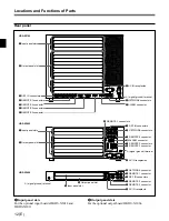
HDS-X3700/X3600/X3400 Multi Bit Rate Routing Switcher
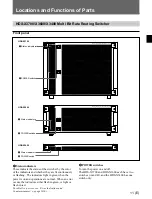
Front panel
1
Status indicators
These indicate the status of the switcher by the color
of the indicators and whether they are lit continuously
or flashing. The indicators light in green when the
power is on and operations are normal. When an error
occurs, the indicators either flash in green, or light or
flash in red.
For details on errors, see “Error Indications and
Countermeasures” on page 16(E).
2
POWER switches
To turn the power on and off.
The HDS-X3700 and HDS-X3600 each have two
switches (A and B), and the HDS-X3400 has one
switch only.
1
Status indicators
2
POWER switches
HDS-X3700
HDS-X3600
HDS-X3400
1
Status indicators
1
Status indicator
2
POWER switch
MULTI BIT RATE ROUTING SWITCHER HDS-X3400
POWER
I
O
MULTI BIT RATE ROUTING SWITCHER HDS-X3700
POWER B
I
O
POWER A
I
O
MULTI BIT RATE ROUTING SWITCHER HDS-X3600
POWER B
I
O
POWER A
I
O
2
POWER switches


