

1-1
FDR-AX1/AX1E_L2
1. SERVICE NOTE
1-1. POWER SUPPLY DURING REPAIRS
In this unit, about 10 seconds after power is supplied to the battery terminal using the regulated power supply (8.4 Vdc), the power is shut off
so that the unit cannot operate.
These following method is available to prevent this.
Method:
Use the AC power adaptor (AC-NB12A).
1-2. PRECAUTION ON REPLACING THE BOARD
After replacing the target board, be sure to perform the adjustment items 1 to 3 and the update of firmware.
About the update of firmware, consult with each Head Quarters.
1. Perform the adjustment items “Initial Machine ID(VC board)” and “Initial Machine ID(MM board)” of the Adjust Manual.
Note:
Other adjustments should not be performed.
2. Perform the update to latest firmware.
3. Perform the adjustment items except items performed at step 1.
•
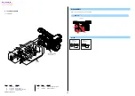
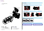
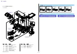
VC-1013 board (MOUNTING BLOCK ASSY)
•
CK-1006 board (CABINET (R) BLOCK ASSY)
•
MM-1003 board (MM BLOCK ASSY)
•
MS-1006 board (MM BLOCK ASSY)
•
PI-1001 board (HANDLE BLOCK)
Refer to Adjust Manual for destination data input, USB Serial number and Product ID input when replacing these boards.
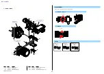
1-3. NOTES FOR REPLACING THE VC-1013 BOARD, MM-1003 BOARD AND MS-1006 BOARD
Replacement method of the VC-1013 board, MM-1003 board and MS-1006 board are different according to the firmware version of the unit.
If the firmware version is Ver.3.00 and later, the VC-1013 board, MM-1003 board and MS-1006 board can be replaced respectively.
If the firmware version is less than Ver.3.00, all of the VC-1013 board, MM-1003 board and MS-1006 board must be replaced to new board.
If the firmware version is not recognized, all of the VC-1013 board, MM-1003 board and MS-1006 board must be replaced to new board.
– ENGLISH –
The changed portions from
Ver. 1.1 are shown in blue.
1-4. SELF-DIAGNOSIS FUNCTION
1-4-1. Self-diagnosis Function
When problems occur while the unit is operating, the self-diagnosis
function starts working, and displays on the Viewfinder or the LCD
screen what to do.
This function consists of two display; self-diagnosis display and service
mode display. Details of the self-diagnosis functions are provided in the
Instruction manual.
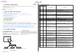
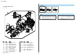
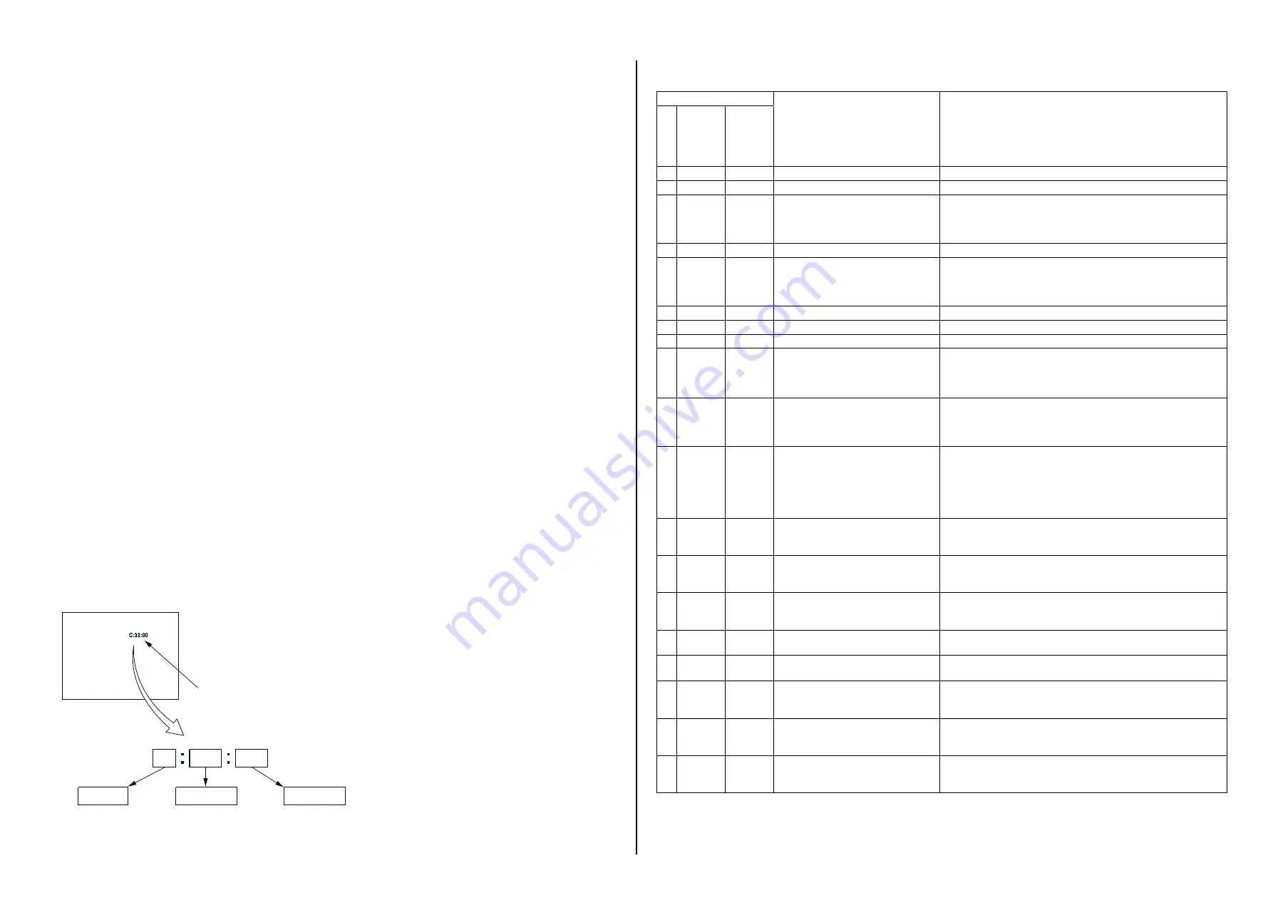
1-4-2. Self-diagnosis Display
When problems occur while the unit is operating, the counter of the
Viewfinder or the LCD screen shows a 4-digit display consisting of an
alphabet and numbers, which blinks at 3.2 Hz. This 5-character display
indicates the “repaired by:”, “block” in which the problem occurred, and
“detailed code” of the problem.
0 0
3 2
C
Repaired by:
Refer to “1-3-3. Self-diagnosis Code Tabl e”.
Indicates the appropriate
step to be taken.
E.g.
13 ....
32 ....Turn on power again.
Block
Detailed Code
Blinks at 3.2 Hz
C : Corrected by customer
E : Corrected by service
engineer
Format the “memory card”.
Viewfinder or LCD screen
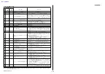
1-4-3. Self-diagnosis Code Table
Self-diagnosis Code
Symptom/State
Correction
Repaired by:
Block
Function
Detailed
Code
C
0
4
0
0
Non-standard battery is used.
Use the InfoLITHIUM battery.
C
0
6
0
0
The battery pack temperature is high.
Change the battery pack or place it in a cool place.
C
3
2
6
0
Difficult to adjust focus
(Cannot initialize focus)
Retry turn the power on by the power switch. If it does not recover, check
the focus MR sensor signal of lens block (pin
4
,
5
of CN6601 or pin
q;
,
qs
of CN6602 on the VC-1013 board). If it is OK, check the focus
motor drive IC (IC6401 on the VC-1013 board).
E
2
0
0
0
Flash memory data are rewritten.
Make flash memory data correct value.
E
4
0
0
0
Abnormality of the video signal processor
Inspect the battery line of IC2201 peripheral circuit on the VC-1013
board. In case of no malfunction, check the connection of between VC-
1013 board and MM-1003 board (FP-2074 flexible board and FP-2075
flexible board).
E
4
1
0
0
Abnormality of network control IC
Turn power off and turn power on again.
E
5
0
0
0
Abnormal of CPU
Turn power off and turn power on again.
E
5
1
0
0
Abnormal of recording or playback
Turn power off and turn power on again.
E
6
1
1
0
Zoom operations fault
(Cannot initialize zoom lens.)
Inspect the zoom MR sensor of lens block (pin
es
,
ef
of CN6602 on
the VC-1013 board when zooming is performed when the zoom lever
is operated, and the zoom motor drive circuit (IC6401 on the VC-1013
board) when zooming is not performed.
E
6
1
1
1
The abnormalities in initialization of
the focus lens and the abnormalities in
initialization of the zoom lens occurred
simultaneously.
Check both C: 32: 60 and E: 61: 10 of the self-diagnosis code.
E
6
1
3
0
Reset position detection error on the step-
per iris initializing
Turn the manual zoom ring to T (telephoto) end after turn power on.
Confirm that the iris blades in lens are working.
If iris blades do not working, check the iris motor drive IC in lens drive
block (pin
qh
to
ql
of CN6602 on the VC-1013 board).
If iris blades work normally, check the iris reset sensor signal in lens
drive block (pin
qd
of CN6602 on the VC-1013 board).
E
6
2
0
0
Handshake correction function does not
work well. (With PITCH angular velocity
sensor output stopped.)
Inspect PITCH angular velocity sensors (SE8501 on the GY-1002 board)
peripheral circuits.
E
6
2
0
1
Handshake correction function does not
work well. (With YAW angular velocity
sensor output stopped.)
Inspect YAW angular velocity sensors (SE8501 on the GY-1002 board)
peripheral circuits.
E
6
2
0
2
Abnormality of IC for steadyshot.
Inspect the steadyshot circuit (IC6401 on the VC-1013 board).
If it does not recover, replace the VC-1013 board. (Note 1)
If an error occurs again, replace the lens block.
E
6
2
0
3
IC for steadyshot and micro controller
communication abnormality among.
Inspect the steadyshot circuit (IC6401 on the VC-1013 board).
E
6
2
0
4
Image vibration correction during hand-
shake function does not work.
Turn power off and turn power on again.
E
6
2
1
0
Shift lens initializing failure.
Inspect the EEPROM (IC3903 on the VC-1013 board).
If it does not recover, replace the VC-1013 board. (Note 1)
If an error occurs again, replace the lens block.
E
6
2
1
1
Shift lens overheating (Pitch)
Inspect the IC6401 on the VC-1013 board and peripheral circuit.
If it does not recover, replace the VC-1013 board. (Note 1)
If an error occurs again, replace the lens block.
E
6
2
1
2
Shift lens overheating (Yaw)
Inspect the IC6401 on the VC-1013 board and peripheral circuit.
If it does not recover, replace the VC-1013 board. (Note 1)
If an error occurs again, replace the lens block.