background image


34

Features / Supplied Accessories

B

Overview

Features

• An EX-view HAD™ CCD features 

380,000 (NTSC) or 440,000(PAL) 
effective picture elements and high-
sensitivity shooting. The minimum 
illumination required is 0.7 lx (1/60 sec. 
(NTSC), 1/50 sec. (PAL), ICR OFF). 
(EVI-D90N/D90P) 

• A CCD features 380,000 (NTSC) or 

440,000(PAL) effective picture elements 
and high-sensitivity shooting. The 
minimum illumination required is 0.4 lx 
(1/60 sec. (NTSC), 1/50 sec. (PAL)). 
(EVI-D80N/D80P)

• The EVI-D90N/D90P are equipped with a 

bright zoom lens with 28× optical zoom 
and F1.35 aperture.

• The EVI-D80N/D80P are equipped with a 

bright zoom lens with 18× optical zoom.

• A newly-developed Processor provides 

high resolution images.

• By adopting its wide and dynamic range 

functions, you can see the optimised 
shooting image which incorporates bright 
and dark subjects at the same time 
(EVI-D90N/D90P).

• 3D Low-noise images can be obtained 

even in low-light environments using the 
Noise Reduction function. 

• Adopts the industry standard RS-232C 

interface of VISCA camera protocol in 
external communication. It is possible to 
operate from long distances by using both 
RS-232C and RS-422.

• You can install the camera on ceilings due 

to the functions of high-speed and wide 
range pan/tilt action and vertical image 
flip.

• You can store up to 6 kinds of camera 

direction and camera status into the 
camera.

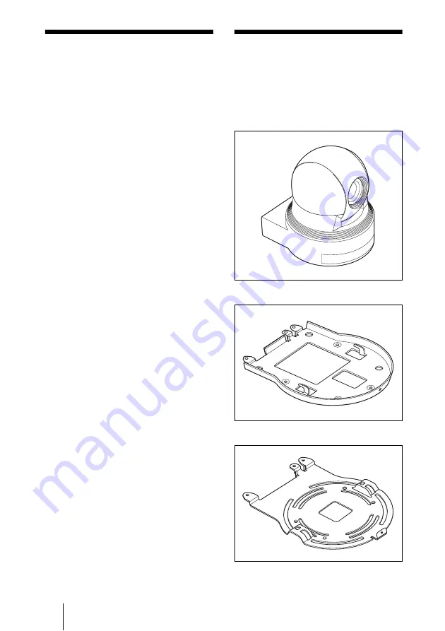
Supplied 
Accessories

When you unpack, check that all the 
supplied accessories are included.

Camera (1)

Ceiling bracket (A) (1)

Ceiling bracket (B) (1)

Summary of Contents for EVI-D80N

Page 1: ..._ GB 4 409 059 11 1 2011 Sony Corporation Color Video Camera EVI D80N D80P D90N D90P お買い上げいただきありがとうございます 電気製品は安全のための注意事項を守らないと 火災や人身事故になることがあります この取扱説明書には 事故を防ぐための重要な注意事項と製品の取 り扱いかたを示してあります この取扱説明書をよくお読みのうえ 製品を安全にお使いください お読みになったあとは いつでも見 られるところに必ず保管してください ...

Page 2: ...い上げ店またはソニーのサービス窓口 にご相談ください すぐに お買い上げ店またはソニーのサービス窓口 にご連絡ください m 1 電源を切る 2 電源コードや接続ケーブルを抜く 3 お買い上げ店またはソニーのサービス窓口に連絡 する 安全のための注意事項を守る 定期点検を実施する 故障したら使用を中止する 万一 異常が起きたら 煙が出たら 異常な音 においがしたら 内部に水 異物が入ったら 製品を落としたりキャビネットを破損したときは 警告表示の意味 取扱説明書および製品 では 次のような表示 をしています 表示の 内容をよく理解してか ら本文をお読みくださ い この表示の注意事項を 守らないと 火災や感 電などにより死亡や大 けがなど人身事故につ な が る こ と が あ り ま す この表示の注意事項を 守らないと 感電やそ の他の事故によりけが をしたり周辺の物品に 損害を与えたりす...

Page 3: ...部の名称と働き 10 カメラ本体 10 設置と接続 設置する 13 デスクトップへ設置する 13 三脚に取り付ける 13 天井に設置する 14 固定用ネジを使って取り付 ける 17 接続する 18 AC 電源への接続 18 コンピューターとの接続 18 コンポジットとビデオ入力端子 S ビデオ入力端子を持つビデ オモニターや VTR との 接続 20 付録 メッセージ一覧 21 故障かな と思ったら 22 仕様 23 VISCA RS 422 端子のピン配列と 使いかた 26 保証とアフターサービスにつ いて 27 ...

Page 4: ...とがあ ります 内部の点検や修理は お買い上 げ店またはソニーのサービス 窓口にご依頼ください 設置は専門の工事業者に依頼する 設置については 必ずお買い上 げ店またはソニーの業務用製 品ご相談窓口にご相談くださ い 壁面や天井などへの設置は 本 機と取り付け金具を含む重量 に充分耐えられる強度がある ことをお確かめの上 確実に取 り付けてください 充分な強度 がないと 落下して大けがの原 因となります また 1年に一度は取り付けが ゆるんでいないことを点検し てください また 使用状況に 応じて 点検の間隔を短くして ください 不安定な場所に設置しない 次のような場所に設置すると 倒れたり落ちたりして 故障や けがの原因になることがあり ます ぐらついた台の上 傾いたところ 振動や衝撃のかかるところ また 設置 取り付け場所の強 度を充分にお確かめください カメラの取り付けネジは確実に締...

Page 5: ... 注意 下記の注意を守らないと けがをしたり周辺の物品に 損害を与えることがあります 機器や部品の取り付けは正しく行う 機器や部品の取り付け方や 本 機の分離 合体の方法を誤る と 本機や部品が落下して け がの原因となることがありま す 取扱説明書に記載されている 方法に従って 確実に行ってく ださい お手入れの際は 電源を切る 電源を接続したままお手入れ をすると 感電の原因となるこ とがあります ...

Page 6: ...梱包し 強い衝撃を与えないようにしてくださ い 本体のお手入れ 汚れがひどいときは 水でうすめた中 性洗剤に柔らかい布をひたし 固くし ぼってから汚れを拭き取り 乾いた布 で仕上げてください アルコール シンナー ベンジンなど は使わないでください 変質したり 塗装がはげたりすることがあります 化学ぞうきんをご使用の際は その注 意書に従ってください 殺虫剤のような揮発性の物をかけた り ゴムやビニール製品に長時間接触 させると 変質したり 塗装がはげた りすることがあります 定期メンテナンスについて 本機は駆動部を持つ製品であるため 使用条件により 磨耗やグリス切れに よる異音が発生する場合があります 性能を維持するため 定期メンテナン スを行うことをおすすめします 異音 などが発生した場合は ソニーのサー ビス窓口にご連絡ください レーザービームについてのご注意 レーザービームは CC...

Page 7: ...撮像素子特有 の現象で 故障ではありません 白点 CCD 撮像素子は非常に精密な技術で作 られていますが 宇宙線などの影響に より まれに画面上に微小な白点が発 生する場合があります これは CCD 撮像素子の原理に起因する もので故障ではありません また 下記の場合 白点が見えやすく なります 高温の環境で使用するとき GAIN 感度 を上げたとき 本機においては カメラの電源を切り 再び電源を入れることで現象が改善す ることがあります 折り返しひずみ 細かい模様 線などを撮影すると ぎ ざぎざやちらつきが見えることがあり ます ...

Page 8: ... です EVI D80N D80P 光学倍率 28 倍 F1 35 の高倍率 明 るいズームレンズを搭載しています EVI D90N D90P 光学倍率 18 倍のズームレンズを搭載 しています EVI D80N D80P 信号処理に新開発の Processor を採 用することで高解像度映像が得られ ます ワイドダイナミックレンジ機能の搭 載により 明るい被写体と暗い被写 体を同時に有している画面にて最適 映像が可能となります EVI D90N D90P 3D ノイズリダクション機能により 低照度においてノイズの少ない映像 が得られます 外部通信で業界標準である VISCA カ メラプロトコルの RS 232C インター フェースを搭載 RS 422 も加えて 長距離でのコントロールが可能です 高速 広範囲駆動のパン チルト機 能と Image flip 上下反転 機能によ り 天井への設...

Page 9: ...9 付属品 概要 付属品 梱包をあけたら 以下の付属品が一式 そろっているか確認してください カメラ本体 1 シーリングブラケット A 1 シーリングブラケット B 1 ワイヤーロープ 1 取り付け用ネジ M3 8 8 VISCA RS 422 コネクタープラグ 1 取扱説明書 1 ...

Page 10: ...灯します このランプが点灯してから 映像が 出力されるまでに約 7 16 秒ほど かかります D STANDBY ランプ スタンバイ状態のとき 点灯しま す 背面 E リモコン受光部 F IMAGE FLIP スイッチ 映像の上下反転を行います 通常は OFF で使用します 天井に設置す るときは ON で使用します IMAGE FLIP を切り換えるには 本機の電源が切れている状態 スタ ンバイ状態も含む で その後 DC 電源 VISCA 通信のいずれかで電 源を入れてください 切り換えた 際 プリセットされていた設定が初 期設定にもどります 映像が出るま で約 7 16 秒ほどかかります カメラ本体 2 3 4 1 ...

Page 11: ...A IN 端子 RS 232C で通信する場合に接続しま す 複数のカメラを接続するときは 前 のカメラの VISCA OUT 端子と接 続します L VISCA OUT 端子 複数のカメラを接続するとき 次の カメラの VISCA IN 端子と接続しま す M DC 12V 端子 この製品には 極性統一形プラグ JEITA 規格 タイプ 4 をご使用 ください 底面 N 三脚取り付け部 O BOTTOM スイッチ RS 232C と RS 422 の切り換え ボーレート 9 600 bps と 38 400 bps の切り換え D70 モードへの切り換 え IR OUT 出力設定に使用しま す 詳しくはテクニカルマニュアル をご覧ください P 天井設置用ブラケット取り付けネ ジ穴 機器の名称と電気定格は 底面に表示さ れています ご注意 極性統一形プラグ 重要 ...

Page 12: ...2 インターフェース経由で VISCA コマンドを使用してカラー ビデオカメラを操作するにはこのス イッチを ON にします モードを切り換えるには 本機の電 源が切れている状態 スタンバイ状 態を含まない で BOTTOM スイッ チを切り換え その後 DC 電源を入 れてください 電源投入後の切り換 えには対応しません D BAUD RATE SELECT スイッチ ボーレート 38 400 bps でカメラを操 作するにはこのスイッチを ON ボーレート 9 600 bps でカメラを操 作するにはこのスイッチを OFF に します モードを切り換えるには 本機の電 源が切れている状態 スタンバイ状 態を含まない で BOTTOM スイッ チを切り換え その後 DC 電源を入 れてください 電源投入後の切り換えには対応しま せん E スイッチ 5 未使用 常に OFF に設定します ...

Page 13: ...さないでください 故障の 原因となります 未接続でカメラヘッド部を手で回すと 本体前面のランプが点灯する場合があ りますが これは故障ではありません 三脚の取付部のネジは取付面から飛び 出し量 4 が下記のものを使用し ハ ンドドライバーで締めこんでください 4 4 3 mm 5 mm 4 0 17 インチ 0 20 インチ 設置は確実に 設置については 必ずお買い 上げ店またはソニーのサービ ス窓口にご相談ください 設置は 本機と取り付け金具 を含む重量に充分耐えられる 強度があることをお確かめく ださい 充分な強度がない と 落下して 大けがの原因 となります また 一年に一度は 取り付 けがゆるんでいないかを点検 してください デスクトップへ設置する ご注意 三脚に取り付ける 三脚用ネジによる固定は 高所への設置 には使用しないでください ...

Page 14: ...た場合は 1 年に一度は 取り付けがゆるんでいないことを点 検してください また 使用状況に応 じて点検の間隔を短くしてください 設置する前に カメラの撮影方向を決めてから 天井 にジャンクションボックス 接続ケー ブル用の各穴を開けておきます 接続ケーブルは シーリングブラケッ ト A の中を通して配線できません 天井の本体後部の位置に 配線用の穴 が必要です 設置のしかた 1 カメラ後面のIMAGE FLIPスイッ チを ON にする BOTTOM スイッチが正しい位置 に設定されているかご確認くださ い 詳しくは BOTTOM ス イッチの設定 12 ページ をご 覧ください 電源を入れた後に IMAGE FLIP ス イッチを ON にしても画像は反転 しません もう一度電源を入れな おすと反転します 映像が現れる まで約 7 16 秒ほどかかります IMAGE FLIP スイッチ...

Page 15: ...ット B の形状 で丸みがある方の先端にネジ穴が開 いています あとでカメラの正面に なる位置です カメラが正面を向く よう 向きを調整して取り付けてく ださい 4 シーリングブラケット A を付 属のネジ M 3 x 8 3 本でカメ ラの底面に取り付ける ブラケットのネジ穴をカメラ本体の 穴に合わせて取り付けます ネジは図中の番号順に仮止めしてく ださい 3 はワイヤーロープと共締めしま す 仮止めが終わったら それぞれ のネジをしっかりと締めてくださ い カメラ正面 シーリング ブラケット B 天井 ワイヤーロープ を共締めします M 3 x 8 付属 1 2 3 天井 シーリング ブラケット A ...

Page 16: ...本体内部を破損する恐れ があります 5 シーリングブラケット A の突 起をシーリングブラケット B の穴に差し込み シーリングブラ ケット A を後ろ方向へ押して 仮固定する 5 2ジャンクションボックス等にワ イヤーを取り付けられない場合 はシーリングブラケット B の下記箇所へ取り付けてくださ い 6 カメラ前部を押し上げながら 付 属のネジ M 3 x 8 3 本で 1 から固定する ご注意 天井 シーリング ブラケット B シーリング ブラケット A M 3 x 8 付属 天井 1 ...

Page 17: ...部に負荷 がかからないように処理してくださ い カメラの外しかた 1 設置のしかた の手順6で カ メラを固定したネジ 3 本をはず す 2 カメラ全体を天井側へ押し上げな がら カメラの前方へ動かす フックがはずれ カメラがはずれま す 底面の取り付け用ネジ穴 M3 3 箇所 を使って固定します M3 ネジは 次 の規格のものを使用してください ネ ジは 金具などの段差のない平面に取 り付け しっかり締めてください 4 3 mm 5 mm ご注意 天井 固定用ネジを使って取り付ける M3 ネジ ...

Page 18: ... 近いコンセントに電源プラグを接続して ください 万一 異常が起きた際には 専用遮断装 置を切るか 電源プラグを抜いてくださ い VISCA ケーブル RS 232C クロスタ イプ を接続すると コンピューター で操作できます VISCA ケーブルに ついては お買い上げ店にご相談くだ さい 接続方法 コマンドリストにつ いては テクニカルマニュアルを参照 してください テクニカルマニュアル については お買い上げ店にお問い合わ せください AC 電源への接続 警告 DC 12 V コンピューターとの接続 ご注意 RS 232C 入力へ DC 12 V VISCA IN VISCA ケーブル 別売り コンピューター RS 232C 接続 ...

Page 19: ...の VISCA RS 422 コネクタープラ グを使って接続ケーブルを製作して ください ケーブル作成の際は VISCA RS 422 端子のピン配列 26 ページ を参考にして下さい VISCA RS 422 接続の場合は カメラ 底面の BOTTOM スイッチで RS 422 が選択されていることを確認してく ださい 12 ページ VISCA RS 422 接続時は VISCA RS232 C 接続を行うことはできませ ん VISCA RS 422 接続とVISCA RS 232C 接続のケーブルを同時に配線しない でください 同時に配線すると カメ ラが誤動作することがあります ご注意 RS 232C 入力 へ DC 12 V VISCA OUT RS 422 RS 232C 変換コ ネクタ 別売り コンピューター RS 422 接続 VISCA RS 422 接続ケーブル VISC...

Page 20: ...20 接続する 映像が出力されるまでに約 7 16 秒ほ どかかります コンポジットとビデオ入力端子 S ビデオ入力端子を持つビデオ モニターや VTR との接続 ご注意 S 映像ケーブル 別売り DC 12 V VIDEO ビデオ接続 ケーブル 別売り ビデオモニター VTR など S ビデオ端子へ コンポジット ビデオ端子へ S VIDEO ...

Page 21: ... が ON に設定されています メッセージ 意味と対策 PRESET n OK n はプリセットのポジショ ン番号 1 6 POSITION 1 6 にカメラの状態を記憶させたときに約 3 秒間表示 されます RESET n OK n はリセットのポジション 番号 1 6 POSITION 1 6 に記憶させた値をリセットしたときに約 3 秒間表 示されます ONE PUSH WB OP ワンプッシュオートホワイトバランスが実行されているときに点滅 表示されます ONE PUSH WB OK ワンプッシュオートホワイトバランスが正常に終了したときに点灯 表示されます ONE PUSH WB NG ワンプッシュオートホワイトバランスが失敗したときに点滅表示さ れます ...

Page 22: ...症状 原因 処置 接続したビデオモニ ターに画像が出ない 映像接続ケーブルが正しく接続さ れていない 本機とビデオモニターの接続を確認し てください コンピューターに接続 しても VISCA 通信が できない コンピューターが正しく接続され ていない 本機とコンピューターの接続を確認し てください カメラ底面の BOTTOM スイッチ 12 ページ で VISCA 通信のボー レート 9 600 bps または 38 400 bps が正しく設定されているか確認してく ださい どうしても動作しない DC 12 V の供給の停止を行い しば らくしてからもう一度供給してみてく ださい ...

Page 23: ...写体照度 EVI D80N P 0 4Lux 以下 F1 4 50 IRE EVI D90N P 0 65Lux 以下 F1 35 50 IRE シャッタースピード 1 sec 1 10000 sec 映像 S N 50 dB 以上 パン チルト機能 水平 170 最大速度 100 秒 垂直 90 20 最大速度 90 秒 入出力端子 映像出力 COMPOSITE VBS VIDEO OUT ピンジャック 1 75Ω 不平衡 1Vp p 75Ω 終 端時 同期負 S 映像出力 Y C VIDEO OUT 4 ピンミニ DIN 1 コントロール入 出力端子 VISCA IN 8 ピンミニ DIN RS 232C VISCA OUT 8 ピンミニ DIN RS 232C VISCA RS 422 9 ピン 電源端子 JEITA type4 DC 12 V 端子 その他 入力電圧 DC 12 V...

Page 24: ...気用品安全法で定める基準を満 足した承認品が要求されます ソニー推奨の電源コードセットをご使 用ください 本機の仕様および外観は 改良のため 予告なく変更することがありますが ご了承ください 注意 この装置は クラス A 情報技術装置 です この装置を家庭環境で使用す ると電波妨害を引き起こすことがあ ります この場合には使用者が適切 な対策を講ずるよう要求されること があります VCCI A お使いになる前に 必ず動作確認を 行ってください 故障その他に伴う 営業上の機会損失等は保証期間中お よび保証期間経過後にかかわらず 補償はいたしかねますのでご了承く ださい ...

Page 25: ...25 仕様 付録 寸法図 170 170 104 164 Ø145 上面 166 164 72 8 5 20 9 0 背面 底面 正面 側面 51 5 51 5 77 42 42 60 31 30 42 30 14 20 53 5 53 5 M3 M3 M3 Leg 4 Ø9 A Ø5 ߐ5 1 4 20UNC ߐ6 5 ਃ ࡀࠫⓣ BOTTOM ࠬࠗ 単位 mm ...

Page 26: ...G No 28 18 を付属の VISCA RS 422 コネ クタープラグの接続したい穴に差 し込み 入れた穴に対応するネジ をマイナスドライバーで固定す る ピン番号 機能 1 DTR IN 2 DSR IN 3 TXD IN 4 GND 5 RXD IN 6 GND 7 IR OUT 8 未使用 ピン番号 機能 1 DTR OUT 2 DSR OUT 3 TXD OUT 4 GND 5 RXD OUT 6 GND 7 未使用 8 未使用 VISCA RS 422 端子のピン配 列と使いかた ピン番号 機能 1 TXD IN 2 TXD IN 3 RXD IN 4 RXD IN 5 GND 6 TXD OUT 7 TXD OUT 8 RXD OUT 9 RXD OUT 1 2 3 4 5 VISCA RS 422 6 7 8 9 ...

Page 27: ...の電圧レベルを安定させるた め お互いの GND を接続してく ださい VISCA RS 422 の接続時は VISCA RS 232C との接続は行わ ないでください 保証とアフターサー ビスについて 調子が悪いときはまずチェックを この取扱説明書をもう一度ご覧になっ てお調べください 保証期間と保証条件 本機の保証期間および保証条件は 販 売地域 国内 海外 によって異なる ことがあります お手数ですが お買 い上げ店にお問い合わせ ご確認いた だきますようお願い申し上げます ご注意 マイナスドライバー ワイヤー 1 2 3 4 5 6 7 8 9 ...

Page 28: ...ipment is operated in a commercial environment This equipment generates uses and can radiate radio frequency energy and if not installed and used in accordance with the instruction manual may cause harmful interference to radio communications Operation of this equipment in a residential area is likely to cause harmful interference in which case the user will be required to correct the interference...

Page 29: ...re d alimentation ou débrancher la fiche d alimentation AVERTISSEMENT 1 Utilisez un cordon d alimentation fiche femelle fiche mâle conformes à la réglementation de sécurité locale applicable 2 Utilisez un cordon d alimentation fiche femelle fiche mâle avec des caractéristiques nominales tension ampérage appropriées Pour toute question sur l utilisation du cordon d alimentation fiche femelle fiche ...

Page 30: ...inen Stecker mit den geeigneten Anschlusswerten Volt Ampere Wenn Sie Fragen zur Verwendung von Netzkabel Geräteanschluss Stecker haben wenden Sie sich bitte an qualifiziertes Kundendienstpersonal WICHTIG Das Namensschild befindet sich auf der Unterseite des Gerätes Für Kunden in Europa Australien und Neuseeland WARNUNG Dies ist eine Einrichtung welche die Funk Entstörung nach Klasse A besitzt Dies...

Page 31: ...g the Camera 38 Installing the Camera on a Desk 38 Attaching the Camera to a Tripod 38 Installing the unit on the ceiling 38 Installing the Camera Using the M3 Fixing Screw Holes 42 Connections 42 Connecting to an AC Outlet 42 Connecting a Computer 43 Connecting a video monitor or VTR equipped with a composite or S video input connector 44 Appendix Message List 45 Troubleshooting 46 Specifications...

Page 32: ...ng the main unit When the body of the camera is dirty clean it with a soft cloth that is soaked with a diluted neutral detergent and tightly wrung Then finish with a dry cloth Do not use any type of solvents which may damage the finish When you use a chemical cloth follow its instructions Do not sprinkle volatile matter such as pesticide over your camera nor allow rubber or vinyl to come in contac...

Page 33: ...cision technologies fine white flecks may be generated on the screen in rare cases caused by cosmic rays etc This is related to the principle of CCD image sensors and is not a malfunction White flecks tend to be seen particularly in the following cases during operation at a high environmental temperature when you have raised the gain sensitivity This phenomena may be improved by turning the camera...

Page 34: ...Processor provides high resolution images By adopting its wide and dynamic range functions you can see the optimised shooting image which incorporates bright and dark subjects at the same time EVI D90N D90P 3D Low noise images can be obtained even in low light environments using the Noise Reduction function Adopts the industry standard RS 232C interface of VISCA camera protocol in external communi...

Page 35: ...ctions of Parts and Controls Front A Lens EVI D80N D80P 18 magnification optical zoom lens EVI D90N D90P 28 magnification optical zoom lens B Remote sensors C POWER lamp Lights when the camera is turned on It takes about 7 to 16 seconds to display the image after the lamp lights D STANDBY lamp Lights when the camera is set to standby mode Camera 2 3 4 1 ...

Page 36: ... respond to the setting change G IR SELECT switch Select the camera number when you operate multiple cameras with the same remote commander H VISCA RS 422 connector To communicate via RS 422 use this connector Use the supplied VISCA RS 422 connector plug I VIDEO output connector J S VIDEO output connector K VISCA IN connector Connect to a computer via an RS 232C interface When you connect multiple...

Page 37: ...ed from the infrared remote commander via the VISCA IN connector page 50 or set it to OFF to disable the output C RS 232C RS 422 select switch Set to ON to operate colour video camera using the VISCA command via the RS 422 interface To change the mode turn off the camera not including standby mode first set the switch and then turn on the camera again Mode switching is not possible while the camer...

Page 38: ... and screws you can utilize existing junction boxes etc to attach the camera to the ceiling When you install the unit always install it on a level ceiling If you have to install it on a sloping or uneven ceiling make sure that the place where you install it is within 15 degrees of the horizontal Entrust installation to an experienced contractor or installer when installing the unit on ceilings or ...

Page 39: ...ired in the ceiling at the back of the unit where it is attached to the ceiling Installation 1 Set the IMAGE FLIP switch on the rear panel to ON Make sure that the BOTTOM switch is set to the correct position See Setting of the BOTTOM switches page 37 If you set the IMAGE FLIP switch to ON after turning on the power the image will not be flipped Turn the power off once then on again and the image ...

Page 40: ...tom of the camera using the 3 screws M 3 8 supplied Align the screw holes on the bottom of the camera with those in the ceiling bracket and attach the bracket to the camera Tighten the screws a bit at a time in the numbered order shown in the illustration Attach the wire rope using the screw designated as number 3 above After all of the screws are inserted and temporarily tightened properly secure...

Page 41: ...hed to the junction box attach to the position on the ceiling bracket B in the illustration 6 While pushing up on the front part of the camera attach it using the three screws provided M 3 8 starting with the screw at position 1 7 Connect the cables to the connectors on the rear of the camera Take the proper steps to ensure that the load of the cables connected does not cause problems Ceiling Ceil...

Page 42: ... you can remove the camera Attach the camera using 3 M3 fixing screw holes located on the bottom of the camera Attach the camera to a fitting with a flat surface using M3 screws with the following specifications Connections Use the AC power adaptor and AC power cord to connect the camera to an AC outlet Installing the Camera Using the M3 Fixing Screw Holes M3 screw 4 3 5 mm 4 1 8 7 32 inches Conne...

Page 43: ...connect the camera and the VISCA command list refer to the Technical Manual of the camera For details on obtaining a Technical Manual consult your Sony dealer Make up the cable using the supplied VISCA RS 422 connector plug See Using the VISCA RS 422 connector pin assignments page 50 In the case of VISCA RS 232C connection make sure that the BOTTOM switch is set to RS 232C page 37 It is not possib...

Page 44: ...esult in malfunction It takes about 7 to 16 seconds to display the image Connecting a video monitor or VTR equipped with a composite or S video input connector Note to composite video connector DC 12 V VIDEO Video cable not supplied Video monitor or VTR etc to S Video connector S video cable not supplied S VIDEO ...

Page 45: ...ds when you store camera settings to POSITION 1 to 6 RESET n OK n is a reset position number between 1 and 6 This message appears for about 3 seconds when you reset camera settings stored in POSITION 1 to 6 ONE PUSH WB OP During the white balance adjustment in the ONE PUSH white balance mode this message blinks on the screen ONE PUSH WB OK When the white balance adjustment has been done correctly ...

Page 46: ...nnected properly Check the connection between the camera and video monitor The VISCA control is not available with a computer connected to the camera The computer is not correctly connected to the camera Make sure the connection between the computer and camera is made correctly Check that the baud rate setting 9 600 bps or 38 400 bps is properly made with the BOTTOM switch on the bottom of the cam...

Page 47: ...um panning speed 100 degrees sec Vertical 90 20degrees Maximum tilting speed 90 degrees sec Input output connectors Video output COMPOSITE VBS VIDEO OUT RCA phono jack 1 75 ohm unbalanced 1Vpp at 75 ohm termination Synchronization negative S VIDEO output Y C VIDEO OUT Mini DIN 4 pin type Control input output VISCA IN Mini DIN 8 pin type RS 232C VISCA OUT Mini DIN 8 pin type RS 232C VISCA RS 422 9 ...

Page 48: ...WILL NOT BE LIABLE FOR DAMAGES OF ANY KIND INCLUDING BUT NOT LIMITED TO COMPENSATION OR REIMBURSEMENT ON ACCOUNT OF THE LOSS OF PRESENT OR PROSPECTIVE PROFITS DUE TO FAILURE OF THIS UNIT EITHER DURING THE WARRANTY PERIOD OR AFTER EXPIRATION OF THE WARRANTY OR FOR ANY OTHER REASON WHATSOEVER ...

Page 49: ...m inches 166 6 35 64 164 6 15 32 72 2 27 32 8 5 11 32 20 9 0 Side Bottom 14 9 16 20 25 32 51 5 2 1 32 51 5 2 1 32 77 3 1 32 42 1 43 64 42 1 21 32 42 1 21 32 60 2 3 8 31 1 15 64 30 1 3 16 30 1 3 16 53 5 53 5 2 7 64 2 7 64 M3 M3 M3 Leg 4 Ø9 A Ø5 depth 5 1 4 20UNC depth 6 5 Tripod screw hole BOTTOM switch ...

Page 50: ...male The VISCA RS 422 connector pin assignments Pin No Function 1 DTR IN 2 DSR IN 3 TXD IN 4 GND 5 RXD IN 6 GND 7 IR OUT 8 Not used Pin No Function 1 DTR OUT 2 DSR OUT 3 TXD OUT 4 GND 5 RXD OUT 6 GND 7 No connection 8 No connection Using the VISCA RS 422 connector pin assignments Pin No Function 1 TXD IN 2 TXD IN 3 RXD IN 4 RXD IN 5 GND 6 TXD OUT 7 TXD OUT 8 RXD OUT 9 RXD OUT 1 2 3 4 5 VISCA RS 42...

Page 51: ...ten the screw for that wire using a flat head screwdriver 2 Insert the VISCA RS 422 connector plug into the VISCA RS 422 connector on the rear of the camera In order to stabilize the voltage level of the signal connect both ends to GND Do not make a VISCA RS 232C connection when there is already an existing VISCA RS 422 connection Notes Wire Flat head screwdriver 1 2 3 4 5 6 7 8 9 ...

Reviews: