Sony E 18-55mm F3.5-5.6 OSS Service Manual Download Page 32

SEL1855 (E 18-55mm F3.5-5.6 OSS)

4-3

4-3-1. E-Mount Lens Adjustmentの起動と終了方法

1.   E-Mount Lens Adjustmentの起動

※サービス専用光学ブロック交換後に,E-Mount Lens Adjustmentを使用する際は,[Service Flag OFF (S)]ボタンをクリックして,

フラグ解

除を実施してください。

※調整終了後(エラーでの終了時も含む)は,必ずACアダプターの脱着を行ってください。
※E-Mount Lens Adjustmentを起動するとSeusEXも起動します。

1)  E-Mount Lens Adjustmentを起動する。
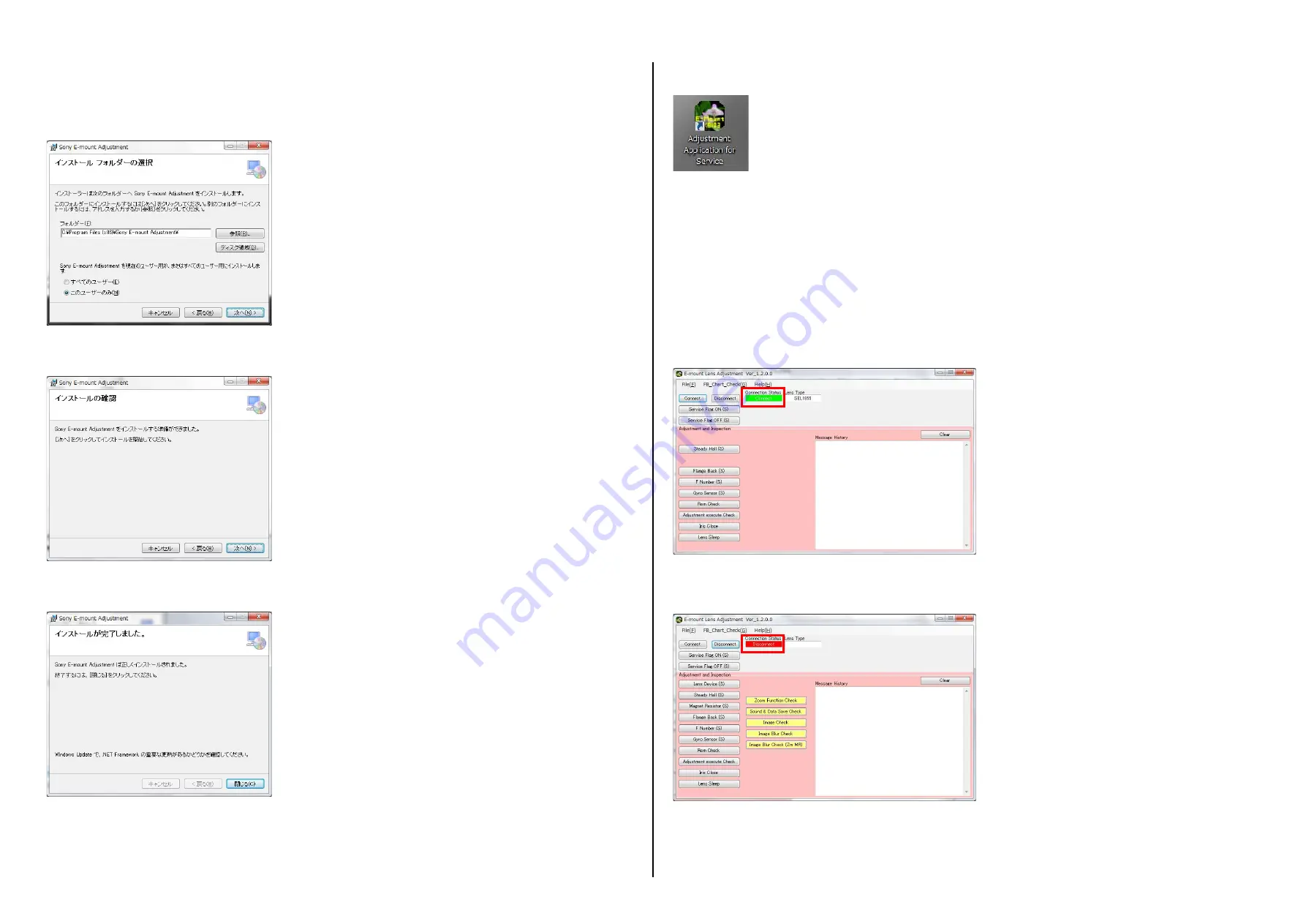
2)  [Connect]ボタンをクリックし,Connection Statusが “Connect” に変化することを確認する。

2.   E-Mount Lens Adjustmentの終了

1)  [Disconnect]ボタンをクリックし,Connection Statusが “Disconnect” に変化することを確認する。

2)  メインウインドウ右上の[

°

]ボタンをクリックし終了する。

4-3.  E-Mount Lens Adjustment

5.  インストール開始画面が表示されるので, [次へ] ボタンをクリックし,インストールを開始する。

6.  インストールが完了すると,下記画面が表示されるので, [閉じる] ボタンをクリックする。

7.  デスクトップにE-Mount Lens Adjustment

(Adjustment Application for Service)

のショートカットアイコンが作成される。

Fig.4-2-4

Fig.4-2-5

Fig.4-2-6

Fig.4-3-1

Fig.4-3-2

Ver. 1.3 2013.04

4.  インストール先フォルダを選択する画面が表示されるので,インストールするユーザーを選択して, [次へ] ボタンをクリックする。

すべてのユーザー: 

インストールを行うPC内すべてのユーザーにインストール

このユーザーのみ: 

現在ログインしているユーザーのみにインストール

Fig.4-2-3

Summary of Contents for E 18-55mm F3.5-5.6 OSS

Page 1: ... of item 2 to NOTE ON REPLACEMENT OF SERVICE EXCLUSIVE OPTICS BLOCK Addition of METHOD OF FIRMWARE UPDATE S M Revised Page 3 4 Addition of REPAIR PARTS LIST Page 3 1 Revision of NOTE ON REPLACEMENT OF SERVICE EXCLUSIVE OPTICS BLOCK Page 3 4 Addition of DISASSEMBLY English Page 2 2 2 7 Japanese Page 2 2 2 7 Addition of REPAIR PARTS LIST Page 3 1 Addition of Section 4 ADJUSTMENTS English Page 4 1 4 ...

Page 2: ...change without notice Included items The value shown above for equivalent 35mm format focal length is for Interchangeable Lens Cameras equipped with an APS C sized image sensor The value shown above for angle of view is for Interchangeable Lens Cameras equipped with an APS C sized image sensor Minimum focus is the shortest distance from the image sensor to the subject Shutter speed differs with sh...

Page 3: ...ip file Decompress FirmwareData_user_Firm_ _ zip 2 Decompress the zip file 101HGPLens UserFirmUpdater zip and save the file FirmwareData_user_Firm_ _ dat decompressed in step 1 into the resource folder close below 3 Connect the NEX 5 camera mounted with NEX 5 camera hereinafter referred to as camera to PC with the USB cable and then turn on the power of camera 4 Run FirmwareUpdater exe 5 Follow in...

Page 4: ...のメッセージが表示されたら セッ トの電源をOFFにしてバッテリーを抜いてく ださい 7 終了 ボタンをクリ ックしてプログラムを終了させてく ださい サービス専用光学ブロック交換時の注意 1 サービス専用光学ブロックを交換した際には E mountレンズをNEX 5に接続し 以下の方法で専用フラグ解除を行ってください レンズ調整プログラム E Mount Lens Adjustment Adjustment Application for Service の Service Flag OFF S を実施する 注意 専用フラグ解除をせずに E mountレンズをNEX 5に接続してもレンズを認識しません F 表示 2 サービス専用光学ブロックはサービス在庫品のため 交換の際は 必ずファームウェアのバージョンを確認してください ファームウェアのバージョンが古い場合は 下記のファームウェアアッ...

Page 5: ...older bridges occur such as on IC pins etc Be sure to control soldering iron tips used for unleaded solder and those for leaded solder so they are managed separately Mixing unleaded solder and leaded solder will cause detachment phenomenon 1 4 SAFETY CHECK OUT After correcting the original service problem perform the following safety checks before releasing the set to the customer 1 Check the area...

Page 6: ...ens use the universal wrench How to Use SERVICE TOOLS Attach the chip A or chip B to the universal wrench For the notches chip A For the holes chip B Match the universal wrench to the holes or notches of the lens block etc B 40 Adhesive bond B 40 J 6082 614 A LOCTITE 460 or the equivalent Adhesive bond LOCTITE 460 or the equivalent SG 310 FT 210 Grease FT 210 9 913 200 37 Grease SG 310 9 913 200 3...

Page 7: ...xed Hold Barrel Assy Zoom Linkage Pin Zoom Linkage Pin Zoom Cover Assy Zoom Cover Assy Cam Pin C Cam Pin B Cam Pin B Cam Pin B Cam Pin B CL 015 Board Complete Noise Guard Sheet Rubber Bushes Rubber Bush Guard Tape MF PI Hold Plate Zoom Cam Barrel Zoom Cam Barrel 1 Group Moving Frame 1 Group Block Assy 1st Group Lens Assy B 40 1 2 3 4 5 9 q qa 8 qs qf qd 6 7 HELP01 HELP03 HELP04 HELP10 HELP12 HELP0...

Page 8: ...sive bond such as instant glue which makes the surface get white after drying Apply adhesive bond LOCTITE 460 to the tip of the stopper screws then tighten them to Mount Assemble Rear Cover Assy by fitting the bosses with the holes on Fixed Hold Barrel Assy Note Take care that do not make the flexible boards get caught when assembling Rear Cover Assy Make folding lines on the flexible board of BL ...

Page 9: ... of 2 Group Lens Assy on the right side 3 Turn Zoom Cover Assy towards WIDE Note Take notice that 2 Group Lens Assy and 3 Group Lens Assy may drop off if turn Zoom Cover Assy until it is in OVER TELE HELP08 1 Turn Zoom Cover Assy towards OVER TELE 2 Pass the flexible board through Fixed Hold Barrel Assy at where the indicated R portion of Outer Barrel matching with the indicated R portion of 3 Gro...

Page 10: ...the flexible board 2 Insert the flexible board of 3 Group Lens Assy into Zoom Cam Barrel Assy while passing it through the hole of Fixed Hold Barrel Assy 3 Turn Zoom Cover Assy to WIDE without catching the flexible board 4 Insert the two FPC Holder plate into the grooves on Fixed Hold Barrel Assy Note Make sure that the tip of the FPC Holders Plate is in the groove on Fixed Hold Barrel Assy Take n...

Page 11: ...Hold Plate and then float PI Note If you wrongly disassembled Outer Barrel and Zoom Cam Barrel reassemble them by fitting the phases of them HELP13 HELP14 1 Assemble Front Cover Assy by fitting the phases at the three places of Bayonet and fitting the direction of the mounting hole of the F lock pin 2 Turn Front Cover Assy in the direction indicated by the arrow and fit it with the inserting hole ...

Page 12: ...rks 2 Apply the adhesive bond B 40 to the indicated portion of the 1 Group Moving Frame three locations A portion 3 Apply the adhesive bond B 40 to the indicated portion of the 1st Group Lens Assy three locations B portion 1st Group Lens Assy A portion A portion B portion B portion three locations three locations 30 to 45 1st Group Lens Assy 1 Group Moving Frame 1 Group Moving Frame Apply the adhe...

Page 13: ...B Note 3 REPAIR PARTS LIST NOTE XX and X mean standardized parts so they may have some difference from the original one Items marked are not stocked since they are seldom required for routine service Some delay should be anticipated when ordering these items The mechanical parts with no reference number in the exploded views are not supplied ns not supplied DISASSEMBLY ENGLISH DISASSEMBLY JAPANESE...

Page 14: ...upplied with the unit as an accessory but is not prepared as a service part Note 当商品はアクセサリーとして同梱されておりますがサービス用補 修部品としては準備しておりません Front Lens Cap X 2546 071 1 Rear Lens Cap 4 159 701 02 Other accessories INSTRUCTION MANUAL Note Lens Hood 4 159 703 02 他の付属品 レンズフロントキャップ X 2546 071 1 レンズリアキャップ 4 159 701 02 取扱説明書 Note レンズフード 4 159 703 02 ...

Page 15: ...f 40 inch LCD monitor Full HD Camera NEX 5 Tripod adaptor optional NOTE The lens adjustment program FB adjustment chart and Resolving power check chart can be downloaded from the TISS homepage For partial adjustments operations on lens side are required Prepare a larger tripod to prevent the lens from wobble Note1 Personal computer The SeusEX must be installed in the PC OS Windows XP Home Professi...

Page 16: ...ogram E Mount Lens Adjustment zip from the TISS homepage 2 Double click the setup exe file 3 The installer screen appears then click the Next button Fig 4 2 2 NOTE Make sure to perform the installation only by the management Do not change the folder to be installed in TELE end Within 10 mm Flange back adjustment jig J 6082 563 A FB Adjustment chart or Siemens star chart J 6080 875 A AC adaptor AC ...

Page 17: ... plug before using the E Mount Lens Adjustment Make sure to disconnect the AC adaptor after finishing the adjustment including the case when stops due to an error SeusEX will start when the E Mount Lens Adjustment is started 1 Start the E Mount Lens Adjustment 2 Click the Connect button and check if the connection status becomes Connect 2 Finishing the E Mount Lens Adjustment 1 Click the Disconnec...

Page 18: ...ck the Iris Close button 7 Click the button on the upper right of the main window to finish E Mount Lens Adjustment 8 Turn off the power of camera NOTE If the PUSH ENTER does not disappear even after pressing the ENTER key press it again Do not touch the focus ring when performing operations on lens side as the focus is on status during adjustment Ver 1 3 2013 04 2 Method for adjusting the Flange ...

Page 19: ...e range Error will occur even if the adjustment value that has ran out of the side of setting value allowable range is returned in the allowable range 6 Press the ENTER key 7 Repeat the operations from steps 4 to 6 to POS8 Fig 4 3 7 Fig 4 3 8 Fig 4 3 9 Ver 1 3 2013 04 4 4 IMAGE QUALITY CHECK ADJUSTMENT 4 4 1 Adjusting Procedure Check Adjusting Procedure Note1 If the result of the projective resolv...

Page 20: ...0 mm and 1500 mm then shoot two times with self timer 4 Check the three images to see if the resolution of the patterns in four corners meets the standard shown in Fig 4 5 2 NOTE Check if the patterns on the four corners are visually as the same resolution Use Adobe PhotoShop to check the image resolution 4 4 1 Adjusting Procedure Fig 4 5 2 Near the limit Check the five patterns in center and four...

Page 21: ...checking lens to be within 10 mm 3 Manually focus to make the center of the siemens star chart match with the center of the LCD 4 Set the camera on the following mode Movie AVCHD 5 Reset the checking lens Set the focus to be Do not touch the focus ring 4 6 2 Take a movie for Flange Back Check 1 Take a movie by operating the zoom as shown below Zoom 55mm 35mm 28mm 24mm 18mm 24mm 28mm 35mm Stop at e...

Page 22: ... 下記の点に注意して使用してください 注意 半田こてを長く当てすぎると 基板のパターン 銅箔 がはがれてしまうことがありますので 注意してください また 従 来の半田よりも粘性が強いため IC端子などが半田ブリッジしないように注意してください 半田こてのこて先は 必ず無鉛半田用と有鉛半田用に分けて管理してください 無鉛半田と有鉛半田が混在すると剥離現象が発生してしまいます 1 4 SAFETY CHECK OUT サービス 点検時には次のことにご注意ください 1 注意事項をお守りください サービスのとき特に注意を要する個所については キャビネット シャーシ 部品などにラベルや捺印で注意事項を表示してい ます これらの注意書き及び取扱説明書等の注意事項を必ずお守りください 2 指定部品のご使用を セットの部品は難燃性や耐電圧など安全上の特性を持ったものとなっています 従って交換部品は 使用さ...

Page 23: ...ンズ専用治具について 分解 または組み立て時に レンズブロック等に以下のような切り欠き または穴がある場合は レンズ専用治具を使用してください 使用方法 副資材について レンズ専用治具にチップA またはチップBを組み付ける 切り欠き用 チップA 穴用 チップB 下図のようにレンズ専用治具をレンズブロック等の穴 または切り欠きに合わせて使用する レンズ専用冶具 J 6082 609 A レンズ専用冶具 チップA J 6082 609 1 レンズ専用冶具 チップB J 6082 609 2 チップ チップ レンズ専用治具 切り欠き または 穴の幅に合わせて 調節する チップB チップB 穴 切り欠き チップA チップA 先端の剥がれたメッキ部は カットして除去する メッキ破片がコネクタ内に 残っている場合もあるので注意 切り欠き 穴 B 40 ボンド B 40 J 6082 614 A ボンド...

Page 24: ...ズーム外装ASSY 2群レンズASSY カムピン C カムピン B カムピン B カムピン B カムピン B 1郡部組 1郡レンズAssy CL 015マウント基板部組 ゴムブッシュ ゴムブッシュ ノイズ防御シート 防御シール MF PI押え板 ズームカム環 1群移動枠 Cam Pin C B 40 1 2 3 4 7 9 q qa 8 qs qf qd 6 5 HELP01 HELP03 HELP12 HELP11 HELP13 HELP09 HELP08 HELP07 HELP05 HELP10 HELP14 HELP04 HELP02 HELP06 HELP15 HELP15 A B C A B C REPAIR PARTS LIST The changed portions from Ver 1 2 are shown in blue Ver 1 3 2013 04 ...

Page 25: ... 注意 ボンド ロックタイ ト460 または相当品を使用すること 瞬間接着剤のように 乾燥後に表面が白くなるボンドは使用しないこと ストッパービスのネジ先端にボンド ロックタイ ト460 を塗布し マウントに締め付ける BL接点ボックスASSYの指示部に折り癖をつける マウントを取り外すとき BL接点ボックスのフレキを必ず切り離してからマウントを取り外してください 後部外装ASSYのボスと固定保持環部組の穴を合わせて後部外装ASSYを組み付ける 注意 後部外装ASSYを組み付けるときは ズームをオーバー TELE端以外にセッ トしてから フレキを挟まないようにするこ と マウント グリス SG 310 塗布する 爪部裏側 フレキ マウント 山折り 谷折り ボンド ロックタイト460 塗布 マウント フレキ 後部外装ASSY ボス ...

Page 26: ...フレキを固定保持環の中へ通す 3 3群レンズASSYのカムピンをズームカム環の内側のカム溝に合わせて組み付ける 4 ズームをWIDE方向に回転させる 注意 オーバー TELE端までズーム外装ASSYを回転させると3群レンズASSYが落下する恐れがあります 1 ズーム外装ASSYをオーバー TELE側へ回転させる 2 前外装ロックピン側を手前にする 3 2群レンズASSYの切り欠き部が 右側になるように2群レンズASSYのカムピンをズームカム環の内側のカム溝に 合わせて組み付ける 4 ズームをWIDE方向に回転させる 注意 オーバー TELE端までズーム外装ASSYを回転させると2群レンズASSY 3群レンズASSYが落下する恐れがあります HELP07 HELP06 HELP08 ズーム外装ASSY カムピン 55 ズーム外装ASSY 1群移動枠 1群移動枠 1群移動枠 カムピン 2群レン...

Page 27: ...合わせてズーム外装ASSYを組み付ける 5 ズーム外装ASSYをWIDE側 マウント側から見て左回り へ回す 1 ズーム外装ASSYをオーバー TELE側へ回転させる 2 3群レンズASSYのフレキを固定保持環分組の穴に通しながらズームカム環に挿入する 3 フレキを挟み込まないようにズーム外装ASSYをWIDE位置まで回転させる 4 FPC 固定板 2箇所 を固定保持環部組の溝に挿入する 注意 FPC固定板の先端が固定保持環部組の溝にはまっているこ とを確認する オーバー TELE端までズーム外装ASSYを回転させると3群レンズASSYが落下する恐れがあります HELP09 FPC 固定板 ズーム外装ASSY ズーム連動ピン カメラマウント側 スライド可変抵抗ボス ズーム外装ASSY ズーム外装ASSY 溝 グリス FT 210 塗布する ズーム外装ASSY ...

Page 28: ...ーカス外装ASSYを固定保持環部組に組み付ける 注意 フォーカス外装ASSY内のく し歯をマウント側にする HELP11 HELP12 固定保持環部組に固定環とズームカム環を組み付ける 注意 固定保持環部組と固定環のカメラマウント側の穴の形状を合わせて ズームカム環のズーム連動ピン取り付け穴が 固定保 持環部組のズーム連動ピン取り付け穴と一致していることを確認する 注意 固定環とズームカム環を誤って分解した場合は 固定環 とズームカム環の位相を合わせて組み付ける MF PI押え板を取り外して PIを浮かせる カメラマウント側の穴 ズーム連動ピン取り付け穴 固定環 固定保持環部組 バヨネット 固定筒 ズームカム環 MF PI押え板 PI バヨネット 前外装ASSY 前外装ロックピン バヨネット フォーカス外装ASSY ...

Page 29: ...指標の位置を合わせて1郡レンズAssyを1郡移動枠に取り付ける 1郡レンズAssy バヨネット バヨネット 指標 指標 1郡レンズAssy 印2個 印2個 1群移動枠 1群移動枠 2 1郡移動枠の指示部にボンド B 40 を塗布する 3箇所 A部 3 1郡レンズAssyの指示部にボンド B 40 を塗布する 3箇所 B部 ボンド B 40 を塗布 ボンド B 40 を塗布 1郡レンズAssy 1郡レンズAssy 1群移動枠 30 45 1群移動枠 3箇所 3箇所 A部 A部 B部 B部 4 1郡遮光環を締め付ける 1群遮光環 Ver 1 3 2013 04 ...

Page 30: ...Adjustment Chart pdf 撮影解像力確認チャート Focus Chart A3 pdf 40インチ液晶モニタ Full HD カメラ NEX 5 三脚 任意 注意 レンズ調整プログラム FB調整チャートおよび撮影解像力確認チャートは TISSホームページからダウンロード可能です 一部の調整において レンズ側での操作が必要となりますので レンズを操作した際に ぐらつかないよう大きな三脚をご用意願います Note1 パーソナルコンピュータ SeusEX がインストール済みのもの OS Windows XP Home Professional SP2 以降 Vista 7 RAM 256 MB またはそれ以上を推奨 Windows XP 7 1 GB またはそれ以上を推奨 Windows Vista USB port USB 2 0 を推奨 USB 1 1 でも使用可能 ポートは...

Page 31: ...プログラム E Mount Lens Adjustment zip をダウンロードする 2 setup exeをダブルクリ ックする 3 インストーラー画面が表示されるので 次へ ボタンをクリ ックする Fig 4 2 2 Fig 4 2 1 フランジバック 調整用治具 10mm以内 被検レンズ Tele端 パーソナルコンピュータ SeusExがインストール済みのもの OS Windows XP Home Professional SP2以降 Vista 7 RAM 256MBまたはそれ以上を推奨 Windows XP 7 1GBまたはそれ以上を推奨 Windows Vista USBポート USB 2 0を推奨 USB 1 1でも使用可能 ポートは2個必要 Run time NET Framework 2 0 NET Framework 2 0がインストールされていない PCには レンズ...

Page 32: ... に変化するこ とを確認する 2 E Mount Lens Adjustmentの終了 1 Disconnect ボタンをクリ ックし Connection Statusが Disconnect に変化するこ とを確認する 2 メインウインドウ右上の ボタンをクリ ックし終了する 4 3 E Mount Lens Adjustment 5 インストール開始画面が表示されるので 次へ ボタンをク リ ックし インストールを開始する 6 インストールが完了すると 下記画面が表示されるので 閉じる ボタンをク リ ックする 7 デスク トップにE Mount Lens Adjustment Adjustment Application for Service のショートカッ トアイコンが作成される Fig 4 2 4 Fig 4 2 5 Fig 4 2 6 Fig 4 3 1 Fig 4 3 2...

Page 33: ...NISHED と表示されるので OK ボタンをク リ ックする Fig 4 3 3のようにMessage Historyへ調整結果が表示されます Clear ボタンをクリ ックすると Message Historyに表示されている履歴が消去されます 注意 ENTERを押しても PUSH ENTER が消えない場合は 再度ENTERを押してく ださい 調整時はフォーカスが となりますので レンズ側での操作の際にフォーカスリングを触らないでく ださい Fig 4 3 3 Ver 1 3 2013 04 2 ズームをWIDE端にセッ トし ENTERを押す 3 ズームをTELE端にセッ トし ENTERを押す Fig 4 3 5 Fig 4 3 6 2 Flange Back S の調整方法 Flange Back S の項目については レンズ側での操作が必要となります 以下に調整方法を掲載しま...

Page 34: ...ig 4 3 7 6 ENTERを押す 7 上記4 6 の操作を POS8 まで繰り返す Fig 4 3 8 8 調整が完了すると Fig 4 3 9の画面が表示されます Fig 4 3 9 9 ポップアップウインドウ右上の ボタンを押す ボタンを押すと FINISHED のダイアログボックスが表示されます 4 4 画質の確認 調整 4 4 1 調整手順 確認 調整手順 Note1 撮影解像力の確認で片ボケがNGの場合は 1群部組を交換してく ださい 1群部組の部品交換を行っても改善しない場合は サービス専用光学ユニッ トの交換を行ってく ださい Note2 フランジバックの確認 調整後 でNGの場合は 以下の順に部品の交換を行ってく ださい 1 ズームカム環 2 1群部組 1 2の部品交換を行っても改善しない場合は サービス専用光学ユニッ トの交換を行ってく ださい 撮影解像力 片ボケ ...

Page 35: ...設置し ズームをTELE端にする 3 ピントを合わせてチャートが上下左右均等になるように配置する 4 5 撮影解像力の確認 調整 4 5 1 準備 1 4 5 1 準備 の状態で マニュアルフォーカスに設定する 2 ピントを合わせて セルフタイマーで撮影する 3 ピントは手順2 の状態のままで 撮影距離を 1300mm 1500mm にし 2枚セルフタイマーで撮影する 4 撮影画像3枚の結果から 周辺の解像がFig 4 5 2で示す基準を満たしているか確認する 注意 周辺4隅が同じ解像で見えるこ とを確認してく ださい Adobe PhotoShop等を使用して 解像の確認を行ってく ださい 4 5 2 撮影解像力 片ボケ の確認 4 4 1 調整手順 1郡レンズAssy 1群移動枠 4 4 1 調整手順 2 片ボケが改善されるまで 片ボケ確認と片ボケ調整を繰り返す 注意 調整を行っても片...

Page 36: ...0 400lux または 35 65cd m2 になるようにしてく ださい ジーメンススターチャートは光源ムラがないようにしてく ださい 2 TELE端にしたとき フランジバック調整用治具のレンズから被検レンズの先端まで 10mm 以内にセッ トする 3 マニュアルフォーカスにてLCDの中心に ジーメンススターチャートの中心が来るように正対させる 4 カメラを以下のモードに設定する 動画 AVCHD 5 再度 被検レンズを装着し直す フォーカスが となる フォーカスリングには絶対に触れないでく ださい 1 以下のようにズーム操作を行い 映像を撮影する ズーム 55mm 35mm 28mm 24mm 18mm 24mm 28mm 35mm ズームをそれぞれの位置で止めてく ださい 1 上記で撮影した映像を液晶モニタで再生する 著しいピントボケ 中心像移動 像ユレ 像トビがないこ とを確認して...

Reviews: