background image

41

Playback

C

hap

te

r 3

  Re

co
rd

in

g an

d Pl

a

yba

c

k

Note

When controlling this unit from external equipment, set 
the REMOTE I/F menu item 

(see page 69)

 and the Control 

mode selector so that the remote mode indicators in the 
display section are on or off as follows.

When using an editing control unit connected to the 
REMOTE IN (R) connector:

When using an RM-LG2 connected to the 
CONTROL connector:

When using equipment connected to the 

S400(i.LINK) connector:

For description on how to carry out search operations via 
external equipment, see the operating instructions for the 
equipment.

Cueing Up a Desired Cue Point

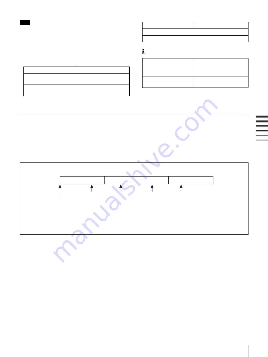
When you have started this unit, the cue pointer is 
automatically positioned at the top of the disk (or the start 
point of the first-recorded clip). 
When you press the NEXT button with the 

J

 (CUE) 

button held down, the cue pointer jumps to the first-
registered cue point. A second press of the NEXT button 

with the 

J

 (CUE) button held down makes the cue pointer 

jump to the second-registered cue point, a third press 
makes the cue pointer to the third-registered cue point, and 
so on.
When you press the PREV button with the 

J

 (CUE) button 

held down, the cue pointer jumps to the previous cue point. 

If cue points are registered as shown in the above figure, 
pressing the NEXT button repeatedly with the 

J

 (CUE) 

button held down makes the cue pointer jump in the order 
ARBRCRD.
To jump back from point D to point B for example, press 
the PREV button twice with the 

J

 (CUE) button held 

down.

Switch/menu item

Setting

Control mode selector

REMOTE
(REMOTE indicator lights.)

REMOTE I/F menu item

9PIN
(9P indicator lights.)

Switch/menu item

Setting

Control mode selector

LOCAL

REMOTE I/F menu item

Switch/menu item

Setting

Control mode selector

REMOTE
(REMOTE indicator lights.)

REMOTE I/F menu item

i.LINK
(i.LINK indicator lights.)

A

D

B

C

Top of disk: The initial position of the cue pointer 
when you have started the unit.

Clip 1

Clip 2

Clip 3

A: First-registered cue point
B: Second-registered cue point
C: Third-registered cue point
D: Fourth-registered cue point

Summary of Contents for DVCAM DSR-DR1000A

Page 1: ...DSR DR1000A DR1000AP 2005 Sony Corporation 3 986 592 11 1 Video Disk Recorder Operating Instructions Before operating the unit please read this manual thoroughly and retain it for future reference ...

Page 2: ...y with the cart stand tripod bracket or table specified by the manufacturer or sold with the apparatus When a cart is used use caution when moving the cart apparatus combination to avoid injury from tip over Unplug this apparatus during lightning storms or when unused for long periods of time Refer all servicing to qualified service personnel Servicing is required when the apparatus has been damag...

Page 3: ...authorized recording of such material may be contrary to the provisions of the copyright laws For customers in Europe DSR DR1000AP only This product with the CE marking complies with both the EMC Directive 89 336 EEC and the Low Voltage Directive 73 23 EEC issued by the Commission of the European Community Compliance with these directives implies conformity to the following European standards EN60...

Page 4: ...ications 25 Using the Internal Time Code Generator 26 Synchronizing Internal and External Time Codes 28 Making Basic Network Settings 29 To Set the IP Address 29 To Set the Subnet Mask 29 To Set the Default Gateway 29 To Set Up a User Account 29 Chapter 3 Recording and Playback Recording 30 Settings for Recording 30 Recording Procedure 32 To Set Cue Points 33 Long time Recording With Video Camera ...

Page 5: ...xtracted From Clips Program Playback 44 Working with Playlists 45 Displaying Playlists 45 Editing Playlists 45 Saving the Current Playlist Data 46 Saving Playlists 46 To Delete a Playlist 47 Exiting the Clip Menu 47 Chapter 5 Network Operations Connecting This Unit to a LAN 48 Network Menu 49 Creating and Editing an Address Book 49 Registering Host information in an Address Book 50 Editing an Addr...

Page 6: ...formation 76 Chapter 7 Connections and Settings Connections With Camera System Event Record ing 78 Connections to a Digital Non Linear Editing System 79 Connections for a Cut Editing System 80 Connections for an A B Roll Editing System 82 Adjusting the Sync and Subcarrier Phases 89 Chapter 8 Maintenance and Troubleshooting Regular Checks 91 Troubleshooting 93 Error Messages 94 Alarm Messages 94 Ap...

Page 7: ...umer DV component digital format High picture quality and high stability Video signals are separated into color difference signals and luminance signals which are encoded and compressed to one fifth size before being recorded to ensure stable and superb picture quality High quality PCM digital audio PCM recording makes for a wide dynamic range and a high signal to noise ratio thereby enhancing sou...

Page 8: ...ts over the range 2 to 2 times normal speed Superimposition function Time code values operation mode indications error messages and other text data can be superimposed on analog composite video signals output from the SUPER connector The SUPER connector is a special connector for output of text information It can be used independently when you are outputting composite video component video S Video...

Page 9: ...al video and audio signals in the DV format and the SBP2 protocol used for high speed transfer of video and audio data By connecting SBP2 compatible nonlinear devices or servers you can transfer data at fast speed Ethernet modular jack You can connect this unit to a LAN to transfer material In addition to transferring clips you can also extract and transfer individual scenes Menu system for functi...

Page 10: ...udio level meters 4 PHONESconnector and control knob 2 SC SYNC control 3 Controlmode selector 5 METER CH 1 2 3 4 button 6 MONITOR SELECT button 0 Status indicators 9 COUNTER SELECT button 3 Audio input output level control section see page 16 2 Video audio input setting section see page 15 1 Display section see page 13 4 Recording playback control section see page 16 6 Menu clip control section se...

Page 11: ...annels 3 and 4 The settings made with this button and the MONITOR SELECT button select the channels for level indications and audio output For more details see 6 MONITOR SELECT button f MONITOR SELECT button Use this button and the METER CH 1 2 3 4 button to select the audio channels for level indications on the audio level meters for audio output via the PHONES connector on the front panel for au...

Page 12: ...tor or ACCESS indicator are lit Doing so may result in the loss of recorded or received data k Audio level meters These two meters indicate the recording audio levels during recording or EE mode and the playback audio levels during playback When the audio level indicated on a meter exceeds 0 dB the OVER indicator for the meter lights The short bars to the right of level indication bars indicate th...

Page 13: ...is selection determines the signals output from the Y CPST R Y S C and B Y S Y SUPER connectors as follows 2 INPUT signal display section 1 OUTPUT signal display section 3 Time data type indicators 4 DVCAM indicator 9 Time counter display 6 REC INHI indicator 7 Disk end alarm indicator 8 REPEAT indicator 0 Remote mode indicators qa VITC indicator qd REC MODE display qs PB Fs display 5 KEY INHI ind...

Page 14: ...m see page 62 is set to ON g Disk end alarm indicator Starts flashing when the remaining capacity of the disk is for about 2 minutes h REPEAT repeat playback indicator Lights when the REPEAT MODE menu item see page 61 is set to ON to enable the repeat playback function i Time counter display Indicates the count value of the time counter time code VITC or user bit data depending on the settings of ...

Page 15: ...s indicated by the i LINK VIDEO indicators in the INPUT signal display section see page 14 Note When the video input is set to the i LINK pressing either the CH1 1 2 button or CH2 3 4 button changes the setting to COMPOSITE Reset the video input b CH1 1 2 audio channel 1 or 1 2 button Each press of this button cycles through the following input audio signal selection options for audio channel 1 wh...

Page 16: ...n set the switch to PB the audio input levels return to the preset levels In the same way if you set VARIABLE switch to PB set the audio output levels and then set the switch to REC the audio output levels return to the preset levels b REC PB LEVEL control knobs These knobs are used to control audio levels function differently depending on the setting of the VARIABLE switch as follows 4 Recording ...

Page 17: ...he AUTO EE SELECT menu item see page 61 to PB If cue points are set see page 33 the NEXT button is used to cue up a cue point see page 41 f STOP button Press this button to stop the recording or playback operation 5 PANEL SELECT section Note The buttons of the PANEL SELECT section cannot be turned on or off during simultaneous recording and playback a R recorder button Press this button turning it...

Page 18: ...indicators One of the indicators lights to show the current or most recent search playback mode JOG indicator Jog mode SHUTTLE indicator Shuttle or variable mode d Search dial Rotate to perform search playback in jog shuttle or variable mode The G indicator lights when you rotate to the right to indicate forward direction playback The g indicator lights when you rotate to the left to indicate reve...

Page 19: ...ch to off c AC IN connector Use the supplied power cord to connect this to an AC outlet d CONTROL connector mini jack Connect the supplied RM LG2 Remote Control Unit e REMOTE IN R OUT P connectors D sub 9 pin You can connect remote control units to these connectors using an optional 9 pin remote cable You can also use this connectors to make cascade connections between several DSR DR1000A DR1000AP...

Page 20: ...IDEO IN connectors for inputting analog video signals Y CPST loop through connectors R Y C B Y The signals you can connect to these connectors depend on the selection made with the VIDEO button in the video audio input selection section The selection is indicated by the VIDEO indicators in the INPUT signal display section The analog video signals that can be input to these connectors are as follow...

Page 21: ...th superimposed text information When Y R B is selected When the CHARA DISPLAY menu item see page 63 is set to ON factory default setting the SUPER connector outputs a composite video signal with superimposed text information b AUDIO OUT 1 3 and AUDIO OUT 2 4 connectors XLR 3 pin male These connectors output analog audio signals The output audio channels are determined by the playback audio mode a...

Page 22: ...gital Interface input connector BNC type This connector inputs digital video and audio signals in SDI format Use the VIDEO button in the video audio input setting section see page 15 to select the required input signal formats The current input signal selections are indicated in the INPUT signal display section see page 14 d SDI OUT1 OUT2 Serial Digital Interface output 1 output 2 connectors BNC t...

Page 23: ... CODE OUT time code output connector BNC type This connector outputs a time code according to the operating state of the unit as follows During playback the playback time code During recording the time code generated by the internal time code generator or the time code input to the TIME CODE IN connector When the EE OUT PHASE menu item see page 66 is set to MUTE no time code is output TIME CODE IN...

Page 24: ...y begins to flash To change a numeric value Press the J CUE button to increase a value Press the j button to decrease a value To return a value to the factory default setting 2002 01 01 00 00 00 press the RESET button To confirm a value Press the SET button To exit the date and time setting menu without changing any values press the MENU button To display the material s recording date and time on ...

Page 25: ...time code generator for DSR DR1000A only D VITC field indication E DSR DR1000A DR1000AP operation mode T C R P L A Y 0 0 0 4 4 7 0 7 B Drop frame indication for time code reader a C Drop frame indication for time code generator a a This character can appear on the DSR DR1000A only The character to appear in these two columns is always a colon on the DSR DR1000AP Time data A Time data type E DSR DR...

Page 26: ...ing the time code generated by the internal time code generator onto a disk In addition you can use the user bits to record such data as the date time scene number or other useful information When an external time code generator is connected to the TIME CODE IN connector the internal time code generator can be locked to synchronized with an external time code REC PAUSE Temporary stop of recording ...

Page 27: ...k OUT buttons to move the flashing digit to the value to be changed 5 Use the J CUE and j buttons to change the value of the flashing digit Enter hexadecimal values 0 to 9 A to F when setting user bit data 6 Repeat steps 4 and 5 until you have set the desired values for all digits To set a value of 00 00 00 00 simply press the RESET button 7 Press the SET button The message NOW SAVING appears on t...

Page 28: ...de generator locks onto the external time code and starts advancing Once the internal time code generator has been synchronized in this way you can disconnect the external time code input and this unit will maintain the synchronized time code Note When the selected input mode is i LINK the i LINK indicator is lit in the INPUT signal display section setting the TC MODE menu item to EXT REGEN causes...

Page 29: ...efault value 255 255 255 000 appears with the leftmost digit 2 flashing Change the value by using the menu and clip operation buttons in the same way as with the IP address To Set the Default Gateway Select DEFAULT GATEWAY in the NETWORK CONTROL screen and press the k OUT button The default value 000 000 000 000 appears with the leftmost digit 0 flashing Change the value by using the menu and clip...

Page 30: ...set the REC MODE menu item see page 68 to NORMAL REC In addition to normal recording this unit is capable of continuous recording see page 34 interval recording see page 34 and pre alarm recording see page 34 REW PLAY F FWD STOP REC INPUT VIDEO AUDIO V SDTI SDTI i LINK SDI SG SDI SG SDI SG ANALOG CH 1 1 2 AES EBU dB 0 12 20 30 40 60 OVER 2 4 CH dB 0 12 20 30 40 60 OVER 1 3 CH OUTPUT VIDEO AUDIO HO...

Page 31: ...s Two audio recording modes with either two channels at 48 kHz or four channels at 32 kHz can be used on this unit It is not possible to select any other mode for example with four channels at 48 kHz If there is a point where the audio mode is switched it is not possible to carry out insert editing over a section including that point Selected time data Time data type indicator Count value of the t...

Page 32: ...ch playback signals coming from a player VCR will be recorded on the tape loaded in the unit Note When controlling this unit from an editing control unit connected to the REMOTE IN R connector of this unit set the Control mode selector to REMOTE turning the REMOTE indicator on When not set the switch to LOCAL turning the indicator off If the REC INHI indicator lights The REC INHIBIT menu item see ...

Page 33: ...on see Cueing Up a Desired Cue Point on page 41 To delete a cue point Cue up the cue point that you want to delete hold down the J CUE button and press the RESET button To delete all cue points select DELETE ALL CUE from the Disk menu and press the k OUT button When the message DELETE ALL CUE appears press the SET button For more information about the Disk menu see Deleting Clips on page 42 Long t...

Page 34: ...ting Recording at an Alarm Input Pre Alarm Recording You can start recording at a position 30 seconds before an alarm trigger signal is detected Data for the recording is saved in advance Recording continues until disk space is exhausted and then the unit automatically enters stop mode To perform continuous recording you need to set the REC MODE menu item see page 68 to PRE ALARM REC The trigger s...

Page 35: ...g simultaneous recording and playback With each press of the LINE OUT SELECT button the indicator light as follows R lights P lights R and P both light R lights P lights Line output signals change as follows according to the lit indicators R lit Signals being recorded P lit Signals being played back Switch Setting 75 Ω termination switch ON or attach a 75 Ω terminator Input switch Set according to...

Page 36: ...s recording and playback Press the STOP button to stop recording or playback You can then exit the mode by pressing the buttons in the PANEL SELECT section so that the buttons go out Setting Points A and B for Repeat Playback You can conduct repeat playback of certain sections You can set the repeat playback start point point A and end point point B by using the current position or inputting time ...

Page 37: ...enu SYSTEM MENU SETUP MENU TC PRESET DISK MENU NETWORK MENU DATE TIME PRESET HOURS METER Monitor screen Time counter display Operational SETUP MENU OPERATIONAL FUNCTION DISPLAY CONTROL TIME CODE SETUP BANK OPERATION NETWORK CONTROL MENU GRADE BASIC Monitor screen Time counter display REP FUNC SETUP MENU OPERATIONAL FUNCTION REPEAT FUNCTION AUTO EE SELECT LOCAL ENABLE STP PC REMOTE REC MODE INTERVA...

Page 38: ...e time counter display while the new setting is being saved in memory Note The new setting may be lost if you power off the unit during the saving operation Wait until the saving operation is completed before powering the unit off If you want to discard the changed value Press the MENU button instead of pressing the SET button to return to the menu display then press the MENU button again to end t...

Page 39: ... the new setting and close the menu 4 Press the PLAY button The unit repeats playback between the repeat start and end points set in step 1 Connecting Multiple Units for Simultaneous Playback Multi Simultaneous Playback You can connect multiple DSR DR1000A DR1000AP units in a cascade connection for simultaneous playback of various different scenes The figure below shows how to make cascade connect...

Page 40: ... You can control fine grained in 61 steps playback over the range 2 times normal speed Playback using the tape speed override TSO function You can use the tape speed override function to adjust the playback speed temporarily This function is convenient for playback phase synchronization with another VCR playing back the same program 1 A Hold down the PLAY button and turn the search dial in the des...

Page 41: ...UE button held down makes the cue pointer jump to the second registered cue point a third press makes the cue pointer to the third registered cue point and so on When you press the PREV button with the J CUE button held down the cue pointer jumps to the previous cue point If cue points are registered as shown in the above figure pressing the NEXT button repeatedly with the J CUE button held down m...

Page 42: ... menu operations To display the delete operation menu select DELETE in the Disk menu and press the k OUT button In the delete operation menu select CLIP or ALL DELETE and press the SET button to delete individual clips or all clips When CLIP is selected Display the clip to delete by playback or search and press the SET button A message DELETE appears asking you to confirm the deletion Press the SE...

Page 43: ...nt you can unprotect the clip by pressing the RESET button When you have protected all of the clips that you want to protect press the MENU button to return to the protect operation menu and press the SET button To Search in Clip Units Clip Jump Press the PREV button or the NEXT button on the front panel PREV button The first press moves to the start point of the clip containing the current positi...

Page 44: ...oint timecode appears in the operation mode display area below the time code display on the monitor screen 5 With the CLIP button held down press the SET button CLIP set appears in the time counter and scene B is registered When the In Out points are registered the In and Out points timecodes disappears and the operation mode is displayed below the time code display on the monitor screen Note An e...

Page 45: ...elect RECALL and press the k OUT button The RECALL screen appears 2 Select one of cliplist1 to cliplist7 and press the k OUT button The confirmation message RECALL appears 3 Press the SET button The selected list appears To hide a playlist Press the K IN button Editing Playlists 1 Select LIST in the Clip menu and then press the k OUT button 2 Select the scene that you want to change and press the ...

Page 46: ...the line above the target scene and the scene numbers are reassigned To cancel the addition Press the MENU button To change the playback order of the scenes 1 Select MOVE and press the k OUT button A playlist that does not contain the target scene appears 2 Use the J CUE button or the j button to highlight the line to which you want to move the scene 3 Press the SET button You are returned to the ...

Page 47: ...NU button To Delete a Playlist 1 Select ALL DELETE in the Clip menu and press the k OUT button The confirmation message ALL DELETE OK appears 2 Press the SET button The current playlist is deleted To cancel the deletion Press the MENU button Exiting the Clip Menu If you want to save the current playlist data press the SET button on the Clip menu screen If you need not save the current playlist dat...

Page 48: ...hange data with computers and other recorders Note Before connecting this unit to a LAN you need to set its IP address subnet mask and default gateway and to set up a user account with a user name and password see Making Basic Network Settings on page 29 LAN Ethernet DSR DR1000A DR1000AP Ethernet Ethernet DSR DR1000A DR1000AP DSR DR1000A DR1000AP ...

Page 49: ...the communications destination in an address book Address book entries contain the host name IP address user name password and login folder of a communications destination You can register up to 50 entries To create or edit an address book select the ADDRESS BOOK item from Network menu and press the k OUT button If nothing is registered in the address book A screen like the one shown below appears...

Page 50: ...tate the search dial in the counterclockwise direction To delete a character after entering it press the RESET button To move the cursor Press the K IN or k OUT button To confirm a host name Press the SET button You are returned to the ADDRESS BOOK DATA screen 3 Next enter the IP address IP user name USER password PASS and folder to use in communications DIR Notes When you are entering an IP addre...

Page 51: ...r another registration number press the SET button with the K IN button held down Pressing the SET button with the K IN button held down adds the changes to the end of the host data list Note A host entry cannot be changed while that host is sending data to or receiving data from this unit or in sending or receiving standby Entries cannot be changed if the address book itself is being sent or rece...

Page 52: ...er of the clip that you want to send appears in the CLIP SEL section at the bottom of the monitor or in the time counter display You are returned to the SEND CLIP screen which displays the number and duration of the selected clip Note Clips cannot be selected while they are being recorded If you select a clip that is being recorded a warning message appears asking you to select another clip 8 Pres...

Page 53: ...en the 30th request is issued the message Request queue full Cannot send clip appears and the transfer is rejected To cancel the transfer In step 5 press the MENU button instead of the SET button Sending Address Book Data The following procedure allows you to share address book data between recorders on the same network by copying the contents of the address book on one recorder to another recorde...

Page 54: ...data that has been recorded on other recorders Note Data cannot be received when there is 10 minutes or less of free disk capacity If free disk capacity has fallen to 10 minutes or less you should make more capacity available by deleting recorded clips before carrying out this operation 1 Select the RECEIVE item on the Network menu and press the k OUT button The RECEIVE CLIP screen appears showing...

Page 55: ...ead of the SET button Saving or Deleting Received Data The NEW CONTENTS indicator on the front panel of this unit light when new data is received Use the following procedure to check the data and to save or delete it 1 Select the NEW CONTENTS LIST item in the Network menu and press the k OUT button A list of received data that has not yet been save appears The list indicates the type of data clip ...

Page 56: ...s of transfer jobs executing or standby and check whether the result of a data transfer was OK or not As required you can then abort the transfer or withdraw a connection request Use the following procedure to display the status list 1 Select the STATUS item on the Network menu and press the k OUT button The status list screen appears The following are displayed to indicate the status EXEC Executi...

Page 57: ...e Status or Result field of the monitor screen or in the time counter display Monitor message Time counter display message Description Not Login Not Login Cannot login Contents Full Cont Full More than 100 data items Disk Full Disk Full Disk is full Timeout Timeout Connection timeout No Clip No Clip Clip not found Send Error Send Err Send error occurred Receive Error Rcv Err Receive error occurred...

Page 58: ...igital hours meter display see Regular Checks on page 91 The items of the setup menu are divided into several functional groups on level 1 and except for the MENU GRADE item the settings themselves are made on level 2 or level 3 Also the menu items are divided into two categories according to how frequently they are accessed the basic items to which frequent access is normally required and the enh...

Page 59: ...SE CHARA DISPLAY CHARA POSITION CHARA TYPE CHARA VSIZE DISPLAY INFO SUB STATUS MENU DISPLAY PEAK HOLD OVER DISP HOLD BRIGHTNESS ALARM REF ALARM TC MODE RUN MODE a DF MODE TC SELECT VITC TCG REGEN UB BINARY GP VITC POS SEL 1 VITC POS SEL 2 VITC OUTPUT EE OUT PHASE MUTE IN SRCH LOCAL ENABLE REC MODE INTERVAL REC REC INHIBIT SEARCH ENABLE MAX SRCH SPEED PREROLL TIME AFTER CUE UP PLAY START Level 1 Le...

Page 60: ... CONTROL SHUTTLE MUTE DV ATT NETWORK CONTROL IP ADDRESS SUB NET MASK DEFAULT GATEWAY ACCOUNT INTERFACE SELECT SETUP BANK OPERATION VIDEO OUTPUT DIGITAL OUTPUT REMOTE I F RECALL BANK1 RECALL BANK2 RECALL BANK3 RECALL BANK4 SAVE BANK 1 SAVE BANK 2 SAVE BANK 3 SAVE BANK 4 INPUT BLANK b SRCH CONTROL SEND RECEIVE ADDRES BOOK NEW CONTENTS LIST STATUS NETWORK MENU CLIP CLIP LIST ADDRESS BOOK TC PRESET DI...

Page 61: ...oint is point A as set by the user REPEAT END REP END Determine whether the repeat end point is the end of the video recorded portion or point B VIDEO END VD end The repeat end point is the end of the video recorded portion B POINT B point The repeat end point is point B as set by the user A PRESET A preset Specify a time code value to be used as the setting of point A For details see Setting Poin...

Page 62: ...peed in search shuttle mode and F FWD fast forward REW rewind mode SHUTTLE SHUTTLE Specify the maximum search speed in shuttle mode X60 X60 Maximum 60 times normal speed X32 X32 Maximum 32 times normal speed X16 X16 Maximum 16 times normal speed F FWD REW F FWD REW Specify the maximum search speed in F FWD REW mode a MAX MAX No maximum search speed is specified X85 X85 Maximum 85 times normal spee...

Page 63: ...e of characters in text superimposed on output from the SUPER connector to the monitor Make the following settings while watching the monitor screen WHITE WITH BKGD White White characters on black background BLACK WITH BKGD Black Black characters on white background WHITE OUTLINE W outline White characters with black outline BLACK OUTLINE B outline Black characters with white outline CHARA VSIZE C...

Page 64: ...ground WHITE OUTLINE W outline White characters with black outline BLACK OUTLINE B outline Black characters with white outline PEAK HOLD Peak hold Set the peak hold time for the audio level meters 1 5 SEC 1 5 sec to OFF OFF Set the peak hold time in the range of OFF no peak hold to 1 5 seconds in 0 1 second steps Factory default setting OFF OFF OVER DISP HOLD Hold OVER Determine whether or not to ...

Page 65: ...ect whether the time code generator and time counter operate in drop frame mode or non drop frame mode Normally select drop frame mode to keep in synchronization with real time The non drop frame mode is useful for example when using computer graphics and working on a frame count basis ON DF ON DF Drop frame mode OFF NDF OFF NDF Non drop frame mode TC SELECT TC select Determine which to display in...

Page 66: ...he output video signal phase See example configuration on page 72 MUTE IN SRCH Mute in SR Select whether to mute the output from the TC OUT connector in search jog shuttle mode OFF OFF Do not mute ON ON Mute VIDEO CONTROL Video Settings related to video control Description of settings INT VIDEO SG Video SG Select the test signal to be output from the internal test signal generator When SG is selec...

Page 67: ...ROCESS CONTROL Proc ctrl C PHASE MODE C Phas MD Select the phase rotation mode for chroma phase control The effect of this setting applies to the output levels of all of the composite video S video SDI and component video signals U V COMPOSITE Cmpst Select this setting when observing the composite video output level using a composite vectorscope PB PR COMPONENT Cmpnt Select this setting when obser...

Page 68: ...ng on and off 2 To save the settings press the MENU button to return to the previous screen then press the SET button Example settings LEVEL SELECT Level Sel REF LEVEL REF Level Select the audio reference level headroom for recording 20 dB 20dB factory default setting for DSR DR1000A 18 dB 18dB factory default setting for DSR DR1000AP 16 dB 16dB 12 dB 12dB CH1 IN LEVEL CH1 input Select the audio l...

Page 69: ...itch allows the text data for superimposition on the monitor screen to be output from the right hand REF VIDEO IN connector marked For more information about this consult your Sony dealer COMPOSITE Composite Composite video signals S VIDEO S Video S video separated Y and C and composite video signals Y R B Y R B Y R Y and B Y component video signals AUDIO OUTPUT Audio Out Select the channels for a...

Page 70: ...BANK2 Recall 2 Recall menu settings from menu bank 2 RECALL BANK3 Recall 3 Recall menu settings from menu bank 3 RECALL BANK4 Recall 4 Recall menu settings from menu bank 4 SAVE BANK 1 Save 1 Save current menu settings to menu bank 1 1 Select the bank you want to save then press the k OUT button Message SAVE OK appears 2 To save press the SET button To quit saving press the RESET button SAVE BANK ...

Page 71: ...amcorder is in genlock mode the time code precision is 0 frames When the camcorder is not in genlock mode it is 1 frame VIDEO IN VIDEO OUT VIDEO LOOP THRU TIME CODE IN TIME CODE OUT VIDEO IN VIDEO LOOP THRU TIME CODE IN TIME CODE OUT VIDEO IN VIDEO LOOP THRU TIME CODE IN TIME CODE OUT Composite video or SDI video and audio signal Time code signal Output device VCR camera etc DSR DR1000A DR1000AP 1...

Page 72: ... OUTPUT PHASE mode The time code output signal is synchronized with the output video signal This mode is appropriate when outputting signals from a single device to a number of recorders using separate cables for video audio and time code In this mode the same time code is recorded on all of the recorders 1 to n Menu control buttons Functions MENU button Opens the menu and launches menu control mo...

Page 73: ...T 8 3 5 7 2 4 6 9 1 Setup menu SYSTEM MENU SETUP MENU TC PRESET DISK MENU NETWORK MENU DATE TIME PRESET HOURS METER Monitor screen Time counter display Menu selection level display Operational SETUP MENU OPERATIONAL FUNCTION DISPLAY CONTROL TIME CODE SETUP BANK OPERATION MENU GRADE BASIC Monitor screen Time counter display Level 1 menu display Display SETUP MENU OPERATIONAL FUNCTION DISPLAY CONTRO...

Page 74: ...Items In step 3 first select MENU GRADE and next select ENHANCED then press the SET button to save the setting in memory With this done when you press the MENU button and the k OUT button to display the setup menu all basic and enhanced items on menu level 1 appear Changing the Settings of Enhanced Items To change the settings of enhanced items first carry out the procedure in the previous section...

Page 75: ...ry default setting has been changed the current setting will be 100 or 50 proceed as follows 1 Either press the RESET button or select the default setting using the J CUE or j button 2 Press the SET button The setting returned to its factory default is saved in memory as the current setting To return all settings to their factory default settings 1 Press the MENU button in the menu control section...

Page 76: ...mation and their meaning In each table the indications given in brackets such as ASM are the indications displayed when the SUB STATUS menu item is set to ALL For the display format when ALL is selected see the next section Setting of SUB STATUS menu item Items of supplementary information displayed TC MODE Operating mode of the internal time code generator REMAIN Remaining capacity of the disk CL...

Page 77: ...nal VITC input to the unit via the i LINK S400 i LINK interface and is generating the same time code value and user bit value as those of the external time code regeneration When the SUB STATUS menu item is set to REMAIN On screen indication Meaning REMAIN 184 min Remaining capacity of the disk in minutes When the remaining capacity has not been calculated REMAIN min appears When the SUB STATUS me...

Page 78: ... sales representative Connections With Camera System Event Recording The figure below shows how to connect this unit to a multi camera system to record sports and other events REMOTE IN R 2 1 1 1 1 3 1 SUPER MONITOR SDI IN SDI OUT 1 REF VIDEO IN REF VIDEO OUT To transmission system Camcorder 1 Router This unit Slow motion controller Reference video signal Video monitor Camcorder 2 175Ω coaxial cab...

Page 79: ...he feeder machine Settings on this unit For details of video audio input and audio mode settings see Settings for Recording on page 30 SDI OUT1 S400 i LINK 1 2 1 DV cable Non linear editing system SDI input i LINK SBP2a on AV C This unit a When using the SBP2 protocol set menu item PC REMOTE to ENA see page 69 2 75 Ω coaxial cable Switch menu item Setting Control mode selector REMOTE REMOTE indica...

Page 80: ...d with the optional DSBK 1501 and DSBK 1504 1504P boards SDI OUT 2 SDI IN MONITOR SUPER REMOTE IN R REMOTE VIDEO OUT Y CPST REF VIDEO IN PLAYER 1 1 3 2 1 2 RECORDER MONITOR VIDEO OUT B Y CPST SUPER 1 3 When you select assemble or insert editing mode on the editing control unit the two DSR 1500A 1500AP units recorder and player will automatically enter the selected editing mode A75 Ω coaxial cable ...

Page 81: ...corrector TBC to operate correctly To ensure this input a reference video signal synchronized with the video signal to the REF VIDEO IN connector Switch menu item Setting LOCAL REMOTE switch REMOTE REMOTE indicator lights DIGITAL OUTPUT menu item SDI SDI indicator lights REMOTE I F menu item 9PIN 9P indicator lights REC FORMAT menu item DVCAM DVCAM indicator lights Switch menu item Setting Control...

Page 82: ... create a final tape a tape that contains a completely packaged program in Betacam format use a DVCAM VCR such as the DSR 1500A 1500AP as the recorder Notes This application requires the DSR 1500A 1500AP unit used as the recorder to be fitted with the optional DSBK 1504 1504P board The DSR 1500A 1500AP units shown in the following figure are fitted with the optional DSBK 1501 and DSBK 1504 1504P b...

Page 83: ...ary to connect a delay unit between the audio mixer s output and the audio input to the DSR 1500A 1500AP recorder Main video monitor Source video monitor Video signal generator DSR 1500A 1500AP recorder Audio mixer Editing control unit PVE 500 etc Control signal DME switcher DFS 700A 700AP etc This unit player 1 UVW 1600 1600P player 2 Video signal Audio signal Reference video signal Delay unit a ...

Page 84: ...nce video signal For details of reference video signals see About reference video signals on page 81 L R L R MONITOR OUT 1 MONITOR OUT 2 Speaker left channel Audio amplifier Audio mixer Cables with RCA phono plugs Speaker right channel REF VIDEO IN REF VIDEO IN 1 2 3 REF VIDEO IN REF VIDEO IN DME switcher DFS 700A 700AP etc DSR 1500A 1500AP recorder UVW 1600 1600P player 2 Editing control unit PVE...

Page 85: ...ER 2 MIXER PLAYER 1 RECORDER REMOTE EDITOR REMOTE REMOTE IN R DSR 1500A 1500AP recorder 9 pin remote control cable not supplied This unit player 1 Mixer control mode selection switch PARALLEL 9 pin remote control cable not supplied UVW 1600 1600P player 2 Editing control unit PVE 500 etc DME switcher DFS 700A 700AP etc 9 pin remote control cable not supplied 9 pin 15 pin mixer control cable not su...

Page 86: ...S COMPONENT 2 VIDEO INPUTS COMPONENT 1 PGM OUT COMPONENT 1 LINE OUT 2 LINE OUT 1 1 2 3 4 MIC LINE IN COMPONENT 1 OUTPUT AUDIO OUTPUT CH 1 CH 2 CH 2 OUT CH 1 OUT CH 2 IN CH 1 IN 1 1 2 3 3 3 3 3 3 VIDEO IN AUDIO IN 2 4 1 3 AUDIO OUT 1 3 2 4 Y R Y B Y 3 3 DME switcher DFS 700A 700AP etc CCable with XLR connectors not supplied Audio mixer DSR 1500A 1500AP recorder UVW 1600 1600P player 2 A 12 pin 3 BN...

Page 87: ...tor screen by setting the CHARA DISPLAY menu item see page 63 to ON factory default setting Switch menu item Setting Control mode selector REMOTE OUTPUT LEVEL menu item see page 68 Normally 4 dBm VIDEO OUTPUT menu item see page 69 Y R B Y R B indicator lights AUDIO OUTPUT menu item see page 69 1 2 CH or 3 4 CH CH 1 2 or CH 3 4 indicator lights VIDEO OUT B Y CPST SUPER MONITOR 2 1 75 Ω termination ...

Page 88: ... Set the VCR constants as follows BVE 600 900 910 2000 PAL model or FXE 100P 120P Set the VCR constants as follows RM 450 RM 450CE Set the DIP switches as follows Left switches Right switches RM 450 Right switches RM 450CE 1 2 3 4 5 6 7 8 9 10 11 12 13 14 15 80 18 00 96 05 05 03 80 0A 08 FE 00 80 5A FF 1 2 3 4 5 6 7 8 9 10 11 12 13 14 15 81 17 00 7D 05 05 02 80 0A 07 FE 00 80 4C FF 7 6 5 4 3 2 1 0...

Page 89: ...adjustment operation 1 Press the SCH button on the vectorscope The vectorscope switches to SCH mode 2 Press the B channel button on the vectorscope This displays the black burst signal from the switcher 3 Press the EXT button on the vectorscope This switches the vectorscope to external synchronization mode 4 Adjust the phase synchronization control on the vectorscope so that the sync and subcarrie...

Page 90: ...el A is in correct phase alignment with the black burst signal on channel B Note When component signals are used the subcarrier phase indicator does not appear 8 Output the player 2 signal from the PVE 500 and repeat steps 6 and 7 to adjust the sync and subcarrier phases of the output from player 2 Align the sync and subcarrier phases of the black burst signal to the reference line Sync phase Refe...

Page 91: ... 10 hour increments T3 RECORDING mode The cumulative total hours of disk operation for recording is displayed in 10 hour increments For the T2 mode and T3 mode there are two types of count a trip count which is resettable and the cumulative total from manufacture which is unresettable Displaying the digital hours meter Use the following procedure 1 Press the MENU button in the menu control section...

Page 92: ...ll appear to the right of the trip value and the slash The following illustrates the digital hours meter indications in the time counter display in all three display modes The right hand indication for each display mode is the indication you can view while holding down the k button in the menu control section T1 OPERATION mode T2 PLAYING mode T3 RECORDING mode To end the digital hours meter displa...

Page 93: ...REMOTE indicator off or change the setting of the LOCAL ENABLE menu item see page 62 to ALL ENABLE During recording or playback the time data is not shown in the time counter display The MENU button has been pressed Press the button once again to exit the menu control mode time code preset mode or digital hours meter display mode In either of the menu control mode and time code preset mode the tim...

Page 94: ...g this unit the unit may sometimes output alarm messages such as the one shown below to the monitor screen and the time counter display Audio problem Symptom Cause Remedy The REC PB LEVEL control knobs do not work The VARIABLE switch on the front panel is set to PRESET Set the VARIABLE switch to REC when recording or set it to PB when playing back Editing restriction Symptom Cause Video cannot be ...

Page 95: ...tion cannot be changed in REC recording mode REC mode Input signal does not conform to DVCAM DV format Unknown Sig Input signal is 625 50 For DSR DR1000A 625 50 sig For DSR DR1000A Input signal is 525 60 For DSR DR1000AP 525 60 sig For DSR DR1000AP Input video is not detected Check the VIDEO indicator in the INPUT signal display section and supply an appropriate video signal No INPUT Input video s...

Page 96: ...ng TCG RUN mode is set to REC RUN Set the RUN MODE menu item see page 65 to FREE RUN REC RUN VIDEO END VIDEO END VIDEO TOP VIDEO TOP Alarm messages and associated directions Alarm message on monitor screen Cause Direction Alarm message in time counter display ...

Page 97: ...rong radio waves Operate the unit in a horizontal position This unit is designed to be operated in a horizontal position Do not operate it on its side or tilted through an excessive angle exceeding 20º Avoid violent impacts Dropping the unit or otherwise imparting a violent shock to it is likely to cause it to malfunction Do not obstruct ventilation openings To prevent the unit from overheating do...

Page 98: ...ty Less than 80 Storage relative humidity Less than 90 Mass 7 5 kg 16 lb 8 oz External dimensions w h d 210 130 422 mm 83 8 5 1 8 16 5 8 inches Video performance Band width Composite S video DSR DR1000A 30 Hz to 4 2 MHz 1 0 dB Y Composite S video DSR DR1000AP 25 Hz to 4 8 MHz 1 0 dB Y Component DSR DR1000A 30 Hz to 5 0 MHz 1 0 dB Y 30 Hz to 1 5 MHz 1 0 5 0 dB R Y B Y Component DSR DR1000AP 25 Hz t...

Page 99: ...286 Vp p DSR DR1000A or 0 3 Vp p DSR DR1000AP 75 Ω burst level Analog audio inputs AUDIO IN XLR 3 pin female 2 4 0 3 6 dBm high impedance balanced For DSR DR1000A only Time code input TIME CODE IN BNC type SMPTE time code DSR DR1000A or EBU time code DSR DR1000AP 0 5 Vp p to 18 Vp p 3 3 kΩ unbalanced Network 100BASE TX 10BASE T RJ 45 type 100BASE TX complied with IEEE 802 3u 10BASE T complied with...

Page 100: ...rol connectors REMOTE IN R OUT P D sub 9 pin female 2 for connection of editing control unit RS 422A standard CONTROL Minijack for connection of the supplied RM LG2 Remote Control Unit and input of the trigger signal S400 i LINK 6 pin complied with IEEE 1394 Accessories supplied AC power cord 1 Remote control unit 1 Operating Instructions English version 1 CD ROM manual 1 Accessories not supplied ...

Page 101: ... of the component signals Non drop frame mode The number of frames of the time code and video run is not adjusted When you use the time code in non drop frame mode the real playback time will be about 86 seconds shorter per day than the time code If you edit frame by frame or if you determine the length of a shot by counting the time code use drop frame mode Non linear editing Editing while playin...

Page 102: ...nd the monitor Time code Signals recorded on the media to supply information on media position such as the hour minute second and frame to assist in setting edit points or searching for particular scenes User bits Sections of time code information consisting of a total of 32 bits that can be used for recording information such as date tape ID number program ID number etc ...

Page 103: ... signal 85 cut editing system 80 digital non linear editing system 79 reference video signal 84 video monitor 87 video audio signal 86 CONTINUOUS REC indicator 12 Continuous recording 34 CONTROL connector 19 Control mode selector 11 COUNTER 12 14 SELECT button 12 Cue point cue up 41 setting 33 Cursor clip operations buttons 18 Cyclical playback 39 D Date time setting 24 Default gateway 29 Digital ...

Page 104: ...deo camera 33 REF VIDEO IN connectors 19 REMOTE 11 indicator 15 Remote control 8 control connectors 100 mode indicators 15 REMOTE IN R OUT P connectors 19 REPEAT indicator 14 Repeat playback 39 RESET button 18 R Y S C connector 21 S S VIDEO indicator 14 Saving 46 SC SYNC control 11 SDI 7 indicator 14 OUT1 OUT2 connectors 22 SDI audio signal input 15 SDI IN connector 22 SDI video signal input 15 Se...

Page 105: ... PHASE mode 71 OUT connectors 21 Video performance 98 test signal 15 VIDEO INPUT PHASE mode 71 VIDEO OUTPUT PHASE mode 72 Video audio input setting section 15 VITC field indication 25 indicator 15 Y Y CPST connector 20 21 Y R B indicator 14 Sony Corporation ...

Reviews: