background image

67

Menu Contents

C

h

ap
te

r 4


 M
e

nu
 S
e

tti

n

gs

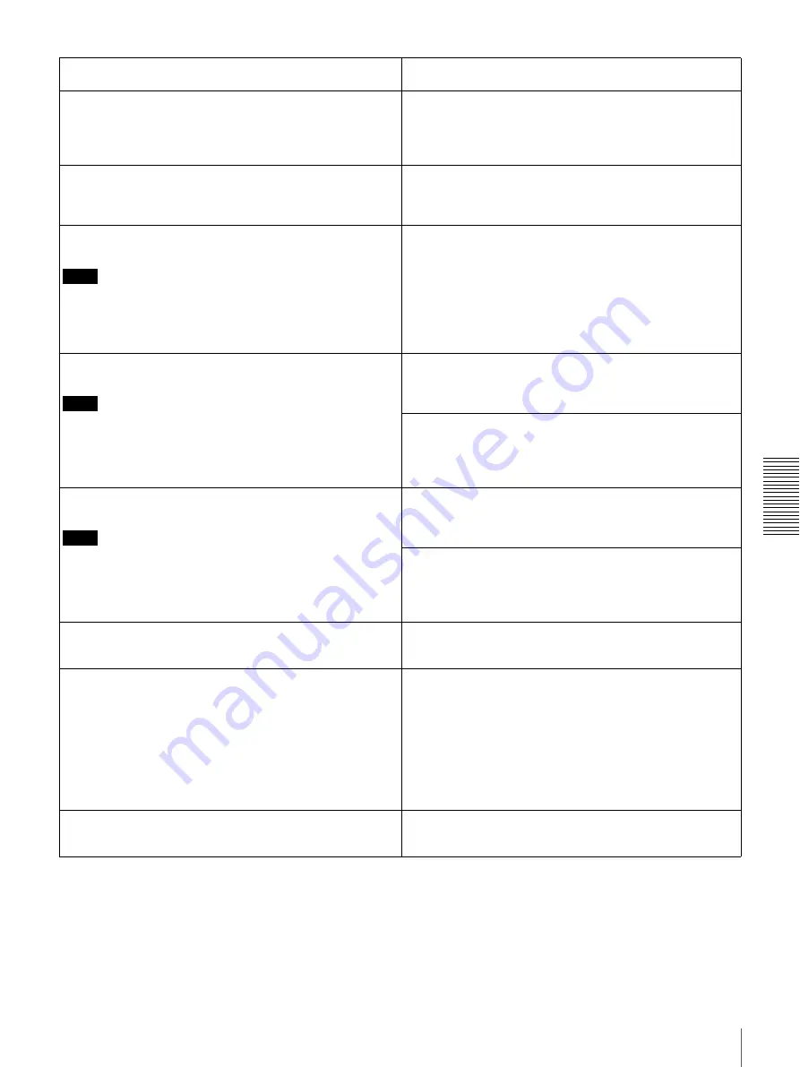
VITC [> VITC]:

 Determine whether to record the internally 

generated time code as VITC. 

OFF [>> OFF]:

 Do not record the internally generated time 

code as VITC. (VITC present in the input video signal is 
recorded unchanged.) 

*

ON [>> ON]:

 Record the internally generated time code as 

VITC.

TCG REGEN [>TCG regen]:

 Select the signal to be 

regenerated when the time code generator is in the 
regeneration mode (i.e., when the TC MODE menu item is 
set to INT REGEN or EXT REGEN).

*

TC & UB [>> TC & UB]:

 Both the time code and user bits are 

regenerated.

TC [>> TC]:

 Only the time code is regenerated.

UB [>> UB]:

 Only the user bits are regenerated.

UB BINARY GP. [> Binary Gp.]:

 Select the user bit binary 

group flag of the time code generator.

Note

When the TC MODE menu item is set to EXT REGEN, the 
user-bit binary group flag setting follows the setting on the time 
code input to this unit.

*

000: NOT SPECIFIED [>> 000]:

 Character set not specified

001: ISO CHARACTER [>> 001]:

 8-bit characters conforming 

to ISO 646 and ISO 2022

010: UNASSIGNED-1 [>> 010]:

 Undefined

011: UNASSIGNED-2 [>> 011]:

 Undefined

100: UNASSIGNED-3 [>> 100]:

 Undefined

101: PAGE/LINE [>> 101]:

 Multiplex

110: UNASSIGNED-4 [>> 110]:

 Undefined

111: UNASSIGNED-5 [>> 111]:

 Undefined

VITC POS SEL-1 [>VITC pos-1]:

 Select a line to insert the 

VITC in.

Note

You can insert the VITC signal in two places. To insert it in two 
places, set both this item and also VITC POS SEL-2.

(For DSR-1800A)

12 LINE [>> 12 line] to 20 LINE [>> 20 line]:

 Select any line 

from 12 to 20.

Factory default setting:

 16 LINE [>> 16 line]

(For DSR-1800AP)
Select a line to insert the VITC in.

9 LINE [>>  9 line] to 22 LINE [>> 22 line]:

 Select any line 

from 9 to 22.

Factory default setting:

 19 LINE [>> 19 line]

VITC POS SEL-2 [>VITC pos-2]:

 Select a line to insert the 

VITC in.

Note

You can insert the VITC signal in two places. To insert it in two 
places, set both this item and also VITC POS SEL-1.

(For DSR-1800A)

12 LINE [>> 12 line] to 20 LINE [>> 20 line]:

 Select any line 

from 12 to 20.

Factory default setting:

 18 LINE [>> 18 line]

(For DSR-1800AP)
Select a line to insert the VITC in.

9 LINE [>>  9 line] to 22 LINE [>> 22 line]:

 Select any line 

from 9 to 22.

Factory default setting:

 21 LINE [>> 21 line]

VITC OUTPUT [>VITC out]:

 Select the time code to be output 

as VITC.

OFF [>> OFF]:

 Do not output VITC.

TC [>> TC]:

 Output TC after converting it into VITC.

*

VITC [>> VITC]:

 Output VITC.

EE OUT PHASE [>EE out]:

 Determine the output phase for 

the LTC signal output from the TIME CODE OUT 
connector when recording time code and in STOP REC 
mode (forced EE mode).

*

MUTE [>>mute]:

 Mute the output.

THROUGH [>> through]:

 Output the time code input to the 

TIME CODE IN connector as it is. 

(See example 

configuration on page 73

.

)

VIDEO INPUT PHASE [>> V input]:

 Output the time code 

with the same phase as the input video signal phase. 

(See example configuration on page 73.)

VIDEO OUTPUT PHASE [>> V output]:

 Output the time code 

with the same phase as the output video signal phase. 

(See example configuration on page 74.)

MUTE IN SRCH [>Mute in SR]:

 Select whether to mute the 

output from the TIME CODE OUT connector in search 
(jog/shuttle) mode.

OFF [>> OFF]:

 Do not mute.

*

ON [>> ON]:

 Mute.

TIME CODE [Time code]: Settings related to the time code 
generator

Description of settings

Summary of Contents for DSR-1800A

Page 1: ...SR series Digital Video Cassette Recorder or Player English Japanese French German Italian and Spanish versions For more details see Using the CD ROM Manual on page 11 Digital Videocassette Recorder Operating Instructions Before operating the unit please read this manual thoroughly and retain it for future reference ...

Page 2: ...cart apparatus combination to avoid injury from tip over Unplug this apparatus during lightning storms or when unused for long periods of time Refer all servicing to qualified service personnel Servicing is required when the apparatus has been damaged in any way such as power supply cord or plug is damaged liquid has been spilled or objects have fallen into the apparatus the apparatus has been exp...

Page 3: ...interface cables used to connect peripherals must be shielded in order to comply with the limits for a digital device pursuant to Subpart B of Part 15 of FCC Rules WARNING Excessive sound pressure from earphones and headphones can cause hearing loss In order to use this product safely avoid prolonged listening at excessive sound pressure levels For the customers in Europe DSR 1800AP only This prod...

Page 4: ...vants E1 résidentiel E2 commercial et industrie légère E3 urbain extérieur et E4 environnement EMC contrôlé ex studio de télévision Le fabricant de ce produit est Sony Corporation 1 7 1 Konan Minato ku Tokyo Japon Le représentant autorisé pour EMC et la sécurité des produits est Sony Deutschland GmbH Hedelfinger Strasse 61 70327 Stuttgart Allemagne Pour toute question concernant le service ou la g...

Page 5: ...prodotto in maniera sicura evitare l ascolto prolungato a livelli eccessivi di pressione sonora Per i clienti in Europa DSR 1800AP soltanto Questo prodotto recante il marchio CE è conforme sia alla direttiva sulla compatibilità elettromagnetica EMC che alla direttiva sulle basse tensioni emesse dalla Commissione della Comunità Europea La conformità a queste direttive implica la conformità alle seg...

Page 6: ... en contra de lo establecido por las leyes de copyright ADVERTENCIA Una excesiva presión de sonido de los auriculares y cascos auriculares puede provocar una pérdida de percepción de sus oídos Para utilizar este producto con seguridad no escuche durante mucho tiempo con niveles de presión de sonido excesivos Para los clientes de Europa DSR 1800AP sólo Este producto con marcado CE cumple con las di...

Page 7: ...ocedure 34 Playback 37 Settings for Playback 37 Playback Procedure 38 Repeat Playback Automatic Cyclical Playback 40 Setting Points A and B for Repeat Playback 40 Cuing Up to Any Desired Position Set as Point A or B 45 Chapter 3 Convenient Functions for Editing Operation Setting the Time Data 47 Displaying Time Data and Operation Mode Indications 47 Using the Internal Time Code Generator 49 Synchr...

Page 8: ...efault Settings 79 Displaying Supplementary Status Information 80 Chapter 5 Connections and Settings Connections for a Digital Non Linear Editing System 83 Connections for a Cut Editing System 85 Connections for an A B Roll Editing System 86 Connections for Analog Recording 91 Adjusting the Sync and Subcarrier Phases 92 Chapter 6 Maintenance and Troubleshooting Maintenance 95 Condensation 95 Regul...

Page 9: ...1 4 inch digital recording format for professional use High picture quality high stability Video signals are separated into color difference signals and luminance signals which are encoded and compressed to one fifth size before being recorded to ensure stable and superb picture quality Because the recording is digital multi generation dubbing can be performed with virtually no deterioration of qu...

Page 10: ...ng the TIME CODE IN OUT connectors The unit is also compatible with VITC Remote control The unit can be operated by remote control from an editing control unit that supports the RS 422A interface or from an optional SIRCS compatible remote control unit such as the DSRM 10 SIRCS Sony Integrated Remote Control System A command protocol to remote control Sony professional videocassette recorders play...

Page 11: ...at digital audio signals to be transferred between this unit and digital Betacam VCRs or other digital equipment RMM 131 1 Rack Mount Kit This kit can be used to mount the unit onto an EIA standard 19 inch rack Using the CD ROM Manual The supplied CD ROM includes Operating Instructions for the DSR series Digital Video Cassette Recorder or Player English Japanese French German Italian and Spanish v...

Page 12: ...ng Instructions English version Contact your Sony service representative When ordering be sure to specify the part number of the manual you want Part No Models covered 3 869 571 1X DSR 1800A 1800AP Intel and Pentium are registered trademarks of Intel Corporation or its subsidiaries in the United States and other countries Microsoft and Windows are registered trademarks of Microsoft Corporation in ...

Page 13: ...tment Accepts DVCAM DV and DVCPRO 25M videocassettes For details of usable cassettes see page 27 d PHONE LEVEL control knob Controls the volume of the headphones connected to the HEADPHONES connector INPUT VIDEO AUDIO i LINK dB 0 12 20 30 40 60 dB 0 1 0 1 2 OVER 1 dB 0 12 20 30 40 60 dB 0 1 0 1 2 OVER 2 dB 0 12 20 30 40 60 dB 0 1 0 1 2 OVER 3 dB 0 12 20 30 40 60 dB 0 1 0 1 2 OVER 4 REC MODE CH11 2...

Page 14: ...lected with the VIDEO IN button in the INPUT SELECT section COMPOSITE Composite video signal Y R B Y R Y and B Y component video signals S VIDEO S video signal SDI SDI video signal optional DSBK 1801 board required SG Video test signal c AUDIO CH1 1 2 display Indicates the input audio signal selected with the CH 1 1 2 button in the INPUT SELECT section ANALOG Analog audio signal AES EBU Digital au...

Page 15: ... settings and channel output format selections MIX A B MARK c MENU button b INPUT SELECT section a MONITOR SELECT switches d COUNTER SEL button f SET YES button e RESET NO button g h TC PRESET button i SC PHASE control j SYNC PHASE control buttons Switch setting Selected channel and output format Left switch Right switch HEADPHONES connector AUDIO MONITOROUT connector Channel 1 only monaural Chann...

Page 16: ...he selection made with this button SDTI i LINK SDTI QSDI interface i LINK selection button Selects digital video and audio signals in i LINK compatible DV format input to the DV IN OUT connector When you press this button the i LINK indicator lights in the input selection audio mode display section c MENU button Press this button to display the menu on the monitor screen and the time counter displ...

Page 17: ...PLAY button while holding down this button it lights and recording begins d PLAY button When you press this button it lights and playback begins If you press this button during recording or editing the recording or editing operation is stopped and this unit enters playback mode e F FWD fast forward button When you press this button it lights and the tape is fast forwarded maximum 85 times normal s...

Page 18: ...in LP mode cannot be played back correctly When a tape recorded in LP mode is played back DV LP flashes and audio is muted b ClipLink indicator Lights when a cassette is loaded on which ClipLink log data is stored in the cassette memory c VITC indicator Lights when VITC is being read or recorded regardless of the data shown in the time counter display a Recording playback format indicators b ClipL...

Page 19: ... when the remaining capacity of the tape is for about 2 minutes l SHUTTLE JOG indicators When searching in shuttle mode using the search dial the SHUTTLE indicator lights and when searching in jog mode using the search dial the JOG indicator lights When the search dial is turned clockwise causing playback to take place in the forward direction the G indicator lights When the search dial is turned ...

Page 20: ...onnector page 25 or DV IN OUT connector page 23 press this button turning it on When reverting to local mode to use the buttons in the tape transport control section press this button again turning it off b 9PIN button When carrying out remote control between this unit and the unit connected to the REMOTE connector press this button turning it on c i LINK button When carrying out remote control be...

Page 21: ...O OUT CH 1 2 OUT IN OUT CH 1 2 CH 3 4 CH 3 4 S VIDEO COMPONENT VIDEO IN COMPONENT VIDEO OUT REF VIDEO Y R Y B Y Y R Y B Y SDI ON 600Ω LEVEL HIGH LOW OFF ON 600Ω LEVEL HIGH LOW OFF ON 600Ω LEVEL HIGH LOW OFF ON 600Ω CH 1 CH 2 CH 3 CH 4 ANALOG VIDEO IN S VIDEO OUT IN 1 2 SUPER OUT IN OUT A Analog video signal input output section see page 22 B Digital signal input output section see page 23 D Extern...

Page 22: ...Y connectors BNC type Input analog component video signals Y R Y B Y to these connectors d REF reference VIDEO IN OUT connectors BNC type Input a reference video signal The IN connector block has a built in automatic 75 Ω termination switch When a signal is input to the left REF VIDEO IN connector with no bridging loop through connection made the connector is terminated with an impedance of 75 Ω a...

Page 23: ...ternal time code generator or the time code input to the TIME CODE IN connector When the EE OUT PHASE menu item see page 67 is set to MUTE no time code is output B Digital signal input output section optional DSBK 1801 board required a DV IN OUT connector 6 pin IEEE 1394 This i LINK compatible connector inputs and outputs digital video and audio signals in DV format Notes When searching at speeds ...

Page 24: ...s shown in the following table according to the audio input levels to the AUDIO IN CH 1 to CH 4 connectors and the required impedance a Selectable on DSR 1800AP only b AUDIO IN CH 1 channel 1 to CH 4 connectors XLR 3 pin female Use these connectors to connect separate channels of analog audio input from a player VCR or other external audio equipment You can switch the audio input level setting wit...

Page 25: ...f the internal digital video processor connect an optional remote control unit to this connector b REMOTE connector D sub 9 pin Use the optional 9 pin remote cable to connect an editing controller that supports this unit or a VCR that supports editing with two units DSR 2000A 2000AP etc to connect those devices to this unit for remote control REMOTE VIDEO CONTROL a VIDEO CONTROL connector b REMOTE...

Page 26: ...26 Location and Function of Parts Chapter 1 Overview ...

Page 27: ...ize DVCPRO 25M cassettes are usable for playback only Notes If you insert an incorrect type of cassette it will be automatically ejected Although this unit can use DV series consumer cassettes video or audio noise may occur on some tapes For reliable playback editing recording and storage use DVCAM cassettes Cassettes that have been recorded by a DV format recorder can be played back on this unit ...

Page 28: ...roblems may occur causing a loss of functions Remove away any dust or dirt from this area before using the cassette If the cassette is dropped on the floor or otherwise receives a hard impact the tape may become slackened and may not record and or play back correctly For information about how to check the tape for slack see the next section Checking the tape for slack Using a paper clip or a simil...

Page 29: ...assettes Inserting a cassette This unit accepts three sizes of cassette L standard size M medium size DVCPRO and S mini size When inserting a cassette in the unit make sure its tape window faces upward as shown in the following figure REC SAVE REC SAVE switch Set to SAVE Outer guides Standard size Tape window facing upward Inner guides Tape window facing upward Mini size Insert the cassette into t...

Page 30: ...uble insertion Ejecting a cassette Press the EJECT button INPUT VIDEO AUDIO V SDTI SDTI i LINK dB 0 12 20 30 40 60 dB 0 1 0 1 2 OVER 1 dB 0 12 20 30 40 60 dB 0 1 0 1 2 OVER 2 dB 0 12 20 30 40 60 dB 0 1 0 1 2 OVER 3 dB 0 12 20 30 40 60 dB 0 1 0 1 2 OVER 4 REC MODE CH11 2 CH23 4 COMPOSITE 2CH4CH PB FS Y R B 48k44 1k32k S VIDEO SDI SG ANALOG AES EBU SDI SG ANALOG AES EBU SDI SG EJECT button ...

Page 31: ...n the video monitor then set its input switches according to the signals input from this unit 2 Set up the player to play back a tape 1 3 7 5 6 4 2 INPUT VIDEO AUDIO V SDTI SDTI i LINK dB 0 12 20 30 40 60 dB 0 1 0 1 2 OVER 1 dB 0 12 20 30 40 60 dB 0 1 0 1 2 OVER 2 dB 0 12 20 30 40 60 dB 0 1 0 1 2 OVER 3 dB 0 12 20 30 40 60 dB 0 1 0 1 2 OVER 4 REC MODE CH11 2 CH23 4 COMPOSITE 2CH4CH PB FS Y R B 48k...

Page 32: ...he required optional digital input output board DSBK 1801 is installed Selected time data Time data type indicator Count value of the time counter COUNTER Time code TC User bit data U BIT Video input signal input connector Corresponding button in the INPUT SELECT section Lit indicator in the input selection audio mode display section Composite signal VIDEO IN VIDEO IN COMPOSITE in VIDEO group Sepa...

Page 33: ... For this reason audio editing between different modes is inhibited on this unit For smooth editing operations check the audio recording mode of the base tape beforehand Once you have started recording you cannot change the audio mode selection If on a tape there is a point where the audio mode is switched it is not possible to carry out insert editing over a section including that point 7 Use the...

Page 34: ...t on When not turn off the button 2 1 3 INPUT VIDEO AUDIO V SDTI SDTI i LINK dB 0 12 20 30 40 60 dB 0 1 0 1 2 OVER 1 dB 0 12 20 30 40 60 dB 0 1 0 1 2 OVER 2 dB 0 12 20 30 40 60 dB 0 1 0 1 2 OVER 3 dB 0 12 20 30 40 60 dB 0 1 0 1 2 OVER 4 REC MODE CH11 2 CH23 4 COMPOSITE 2CH4CH PB FS Y R B 48k44 1k32k S VIDEO SDI SG ANALOG AES EBU SDI SG ANALOG AES EBU SDI SG dB 0 12 20 30 40 60 dB 0 1 0 1 2 OVER 1 ...

Page 35: ...ing and loading cassettes make sure that the unit has been powered on 2 Hold down the REC button and press the PLAY button This puts the unit into recording mode and the tape starts moving 3 Press the PLAY button on the player The player starts the playback operation at which point this unit starts recording the input playback signals Cautions Once you have started recording you cannot change the ...

Page 36: ...is When your current purpose is editing set the unit for the same audio recording mode as with the tape For more details see Troubleshooting on page 98 Operation Do this Stop recording Press the STOP button The unit enters stop mode and will automatically switch to standby off mode after the time period set with the STOP TIMER menu item see page 68 Remove the cassette Press the EJECT button After ...

Page 37: ...Playback 1 Power on this unit by pressing on the side of the POWER switch 2 Power on the video monitor and set its switches as shown below Switch Setting 75 Ω termination switch ON or attach a 75 Ω terminator Input switch Set according to the type of input signal from this unit 2 1 INPUT VIDEO AUDIO V SDTI SDTI i LINK dB 0 12 20 30 40 60 dB 0 1 0 1 2 OVER 1 dB 0 12 20 30 40 60 dB 0 1 0 1 2 OVER 2 ...

Page 38: ...ing operations Indicator It means Cassette memory indicator The loaded cassette contains a cassette memory ClipLink indicator There is ClipLink log data stored in the cassette memory on the loaded cassette NOT EDITABLE indicator The tape was recorded in the DV format or a DVCPRO tape is inserted You cannot use it as a recording tape for editing Operation Do this Stop playback Press the STOP button...

Page 39: ...then rotate the search dial Playback is carried out at the speed according to the speed of the search dial rotation The playback speed range is 1 times normal speed by factory default The search dial has no detents Inhibit the unit from outputting text information time data operation mode indications etc to the video monitor Set the CHARA DISPLAY menu item see page 65 to OFF Remove the cassette Pr...

Page 40: ...Playback You can set the repeat playback start point point A and end point point B by using the current tape position or inputting time code values To perform repeat playback after setting points A and B press the PLAY button when the REMOTE button is off When the DSRM 10 Remote Control Unit is connected to the CONTROL S connector on the front panel you can also start repeat playback by pressing i...

Page 41: ...or B To check the point A or B time code value Press the KA or Bk button on the menu control panel While the button is held down the point A or B time code value is displayed on the monitor and in the time counter display If you hold down the KA and Bk buttons simultaneously the value shown is the point B time code value minus the point A time code value If the point A time code value is greater t...

Page 42: ...f the REPEAT FUNCTION menu item are displayed Operational SETUP MENU OPERATIONAL FUNCTION DISPLAY CONTROL TIME CODE SETUP BANK OPERATION MENU GRADE BASIC Time counter display Monitor screen REP FUNC SETUP MENU OPERATIONAL FUNCTION REPEAT FUNCTION AUTO EE SELECT LOCAL ENABLE STP EJ Monitor screen Time counter display REPEAT MD SETUP MENU OFF T TOP V END OPERATIONAL FUNCTION REPEAT FUNCTION REPEAT M...

Page 43: ...RATIONAL FUNCTION REPEAT FUNCTION REPEAT MODE REPEAT TOP REPEAT END A PRESET B PRESET OFF T TOP V END Monitor screen Time counter display Tape top SETUP MENU OPERATIONAL FUNCTION REPEAT FUNCTION REPEAT TOP TAPE TOP A POINT T TOP V END Monitor screen Time counter display A point SETUP MENU T TOP V END OPERATIONAL FUNCTION REPEAT FUNCTION REPEAT TOP TAPE TOP A POINT Monitor screen Time counter displ...

Page 44: ...in flashing Holding the button down moves the flashing digit continuously If you want to clear the time code value press the RESET NO button The value is cleared to 00 00 00 00 and the leftmost digit begins flashing REP TOP SETUP MENU OPERATIONAL FUNCTION REPEAT FUNCTION REPEAT MODE REPEAT TOP REPEAT END A PRESET B PRESET OFF A V END Monitor screen Time counter display A preset SETUP MENU OPERATIO...

Page 45: ...anged value Press the MENU button instead of pressing the SET YES button to return to the menu display then press the MENU button again to end the menu operation without saving the changed value into memory After the saving operation is completed the monitor screen and time counter display return to the REPEAT FUNCTION setting display as shown in step 9 14To set point B refer to steps 5 to 13 Sele...

Page 46: ...46 Playback Chapter 2 Recording and Playback ...

Page 47: ... be displayed on the monitor screen Time data can also be displayed in the time counter display on this unit To view time data and operation mode indications on the monitor screen Set the CHARA DISPLAY menu item see page 65 to ON factory default setting The time data and the indication of the current operation mode are superimposed on the video signal that is being output from the VIDEO OUT 2 SUPE...

Page 48: ...ed by the time code reader as the new data has not been read correctly from the tape Drop frame mode factory default setting Non drop frame mode T C R P L A Y 0 0 0 4 4 7 0 7 L O C K B Drop frame indication for time code reader a C Drop frame indication for time code generator a a This character can appear on the DSR 1800A only The character to appear in these two columns is always a colon on the ...

Page 49: ... number reel number or other useful information When an external time code generator is connected to the TIME CODE IN connector the internal time code generator can be locked to synchronized with an external time code To set the initial time code value and user bit data 1 Press the COUNTER SEL button to light the time data type indicator TC or U BIT TC To set the initial time code value U BIT To s...

Page 50: ...ff Advancement of internal time code generator The internal time code generator can advance in either of two modes which can be set with the RUN MODE menu item see page 66 FREE RUN Advancement starts when the data saving operation is completed REC RUN Advancement starts when recording starts and stops when recording stops To set the current time as the initial time code value In step 2 above set t...

Page 51: ...d on a tape is discontinuous You can start recording time code from an initial value which can be set freely see page 49 Notes Use a tape which is recorded in the DVCAM format You cannot use the TC insert function with a tape recorded in DV format The time code recording starts from the current tape position Cue the tape up beforehand to the required start position If you use a tape on which ClipL...

Page 52: ... message TC INSERT COMPLETED PUSH THE YES BUTTON appears on the monitor screen and Completed appears in the time counter display 8 Press the SET YES button to exit the menu TC insert AUTO FUNCTION MENU i LINK DUBBING TC INSERT Monitor screen Time counter display Set tape TC INSERT INSERT THE TAPE IN THIS VTR ABORT MENU KEY Monitor screen Time counter display TC insert TC INSERT START TC INSERT STA...

Page 53: ...to 1 30 times normal speed in both directions Note When controlling this unit from external equipment be sure to turn on or off the buttons in the remote control setting section on the front panel of the unit as shown in the following table For description on how to carry out search operations via external equipment see the operating instructions for the equipment Search Operations on This Unit Wh...

Page 54: ... the display section is lit Pressing the search dial toggles between jog mode and shuttle mode 2 Turn the search dial to the desired angle corresponding to the desired playback speed Playback in shuttle mode starts 3 To stop playback in shuttle mode return the search dial to the center position or press the STOP button To return to normal speed playback Press the PLAY button To alternate between n...

Page 55: ...is recorded in this portion it may also not be copied A continuous recorded section of approximately 5 seconds is required before the recording start point It is recommended to record beforehand color bars or a similar signal at the start point of the source tape to be dubbed on this unit Connections for dubbing via i LINK interface To carry out dubbing through the LINK interface connect the i DV ...

Page 56: ... following message appears in step 6 for an A V TC CM dubbing operation When carrying out A V TC CM dubbing if you insert the cassettes in step 6 the cassette memory capacity of the cassettes inserted in both this unit and the player are checked automatically If the cassette memory capacity of the source tape is larger than that of the recording tape the above message appears In this case replace ...

Page 57: ...cording tape the above message appears to confirm whether or not to copy the contents of the cassette memory To copy the contents of the cassette memory press the SET YES button If you do not wish to copy the contents of the cassette memory press the RESET NO button If you press the RESET NO button however the contents of the cassette memory may not agree with the material recorded on the tape Cop...

Page 58: ...58 Digitally Dubbing Signals in DVCAM Format Chapter 3 Convenient Functions for Editing Operation ...

Page 59: ...ge 51 For details of the digital hours meter display see Regular Checks on page 95 The items of the setup menu are divided into several functional groups on level 1 and except for the MENU GRADE item the settings themselves are made on level 2 or level 3 Also the menu items are divided into two categories according to how frequently they are accessed the basic items to which frequent access is nor...

Page 60: ...E DISPLAY INFO SUB STATUS MENU DISPLAY PEAK HOLD OVER DISP HOLD BRIGHTNESS ALARM TC MODE RUN MODE DF MODE a TC SELECT VITC TCG REGEN UB BINARY GP VITC POS SEL 1 VITC POS SEL 2 VITC OUTPUT EE OUT PHASE MUTE IN SRCH REPEAT MODE REPEAT TOP REPEAT END A PRESET B PRESET CASSETTE OUT F FWD REW STOP STANDBY OFF DISPLAY CONTROL TAPE PROTECTION STOP TIMER STILL TIMER NEXT MODE TIME CODE SETUP MENU FROM STO...

Page 61: ...C CM AUTO FUNCTION STILL MODE EE DELAY INT VIDEO SG STD NON STD OUT REF SEL SETUP REMOVE a SETUP ADD a CC F1 BLANK a CC F2 BLANK a WIDE MODE ESR MODE PROCESS CONTROL REC MODE INPUT ARRANGE REC LEVEL LEVEL SELECT INT AUDIO SG OUTPUT CH3 4 OUTPUT PHASE JOG CONTROL SHUTTLE MUTE AUDIO EDIT DV PB ATT DIGITAL PROCESS SETUP BANK OPERATION SYSTEM EE MODE RECALL BANK1 RECALL BANK2 RECALL BANK3 RECALL BANK4...

Page 62: ...er or not to put the unit into repeat playback mode OFF OFF Do not put the unit into repeat playback mode ON ON Put the unit into repeat playback mode ON FREEZE FREEZE Put the unit into freeze playback mode In this case while the unit is cueing up to the repeat start point the freeze picture of the repeat end point is displayed REPEAT TOP REP TOP Determine whether the repeat start point is the beg...

Page 63: ...ll time change or time data display selection are effective REC INHIBIT REC INH Determine whether to prohibit recording on tape OFF OFF Do not prohibit recording on tape ON ON Prohibit recording on tape The REC INHIBIT indicator on the front panel lights A1 EDIT CH A1 Edit CH Determine which audio channel the EDIT PRESET command set on an editing control unit such as the PVE 500 for A1 is assigned...

Page 64: ... still pictures in search mode PLAY START PLAY start Set the timing for switching from stop mode to playback mode In an editing system including an editing control unit such as the PVE 500 you can adjust this setting so that the delay before switching to playback mode is the same on all the decks of the editing system It is then no longer necessary to synchronize the decks for editing and the prer...

Page 65: ... TIME DATA UB Time UB Time data selected using the COUNTER SEL button and user bit data When user bit data is selected using the COUNTER SEL button user bit data and time code are shown TIME DATA CNT Time CNT Time data selected using the COUNTER SEL button and CNT value When CNT is selected using the COUNTER SEL button CNT value and time code are shown TIME DATA TIME Time Time Time data and VITC T...

Page 66: ... from tape EXT REGEN EXT Use external time code selected as follows When TC is selected External time code input to the TIME CODE IN connector When VITC is selected The VITC time code present in the input video signal Note When the selected input mode is i LINK the i LINK indicator is lit in the Input selection audio mode display section setting this item to EXT REGEN causes the internal time code...

Page 67: ...Factory default setting 16 LINE 16 line For DSR 1800AP Select a line to insert the VITC in 9 LINE 9 line to 22 LINE 22 line Select any line from 9 to 22 Factory default setting 19 LINE 19 line VITC POS SEL 2 VITC pos 2 Select a line to insert the VITC in Note You can insert the VITC signal in two places To insert it in two places set both this item and also VITC POS SEL 1 For DSR 1800A 12 LINE 12 ...

Page 68: ...ill image FIELD1 Field 1 Output only field 1 as the still image FIELD2 Field 2 Output only field 2 as the still image EE DELAY EE delay An E E video signal is output delayed with respect to the video input signal by the time for video circuit processing With this item select whether or not to delay the sync signal attached to the output video signal by an amount corresponding to the video signal d...

Page 69: ...MENU MENU Use the setup menu to change the settings for the internal digital video processor C PHASE MODE C Phas MD Select the phase rotation mode for chroma phase control The effect of this setting applies to the output levels of all of the composite video S video SDI and component video signals U V COMPOSITE Cmpst Select this setting when observing the composite video output level using a compos...

Page 70: ...the settings press the MENU button to return to the previous screen then press the SET YES button Example settings REC LEVEL Rec level Determine whether to enable or disable the AUDIO INPUT LEVEL control knobs on the front panel VARIABLE Variable Enable PRESET Preset Disable AUDIO INPUT SOURCE ARRANGE in1 in2 in3 in4 ch1 on ch2 on on ch3 on ch4 on ON OFF SET KEY TO MENU MENU KEY 1 2 3 4 1 Input au...

Page 71: ... AUDIO SG Audio SG Select the operation of the internal audio test signal generator SILENCE silence Silent signal 1kHz SINE 1kHz 1 kHz 20 dB FS sine wave signal When you select SG as the audio input in the INPUT SELECT section on the front panel the audio test signal generated by the internal audio test signal generator is input OUTPUT CH3 4 OUT ch3 4 Select the signals to be output from the AUDIO...

Page 72: ...operations Description of settings RECALL BANK1 Recall 1 Recall menu settings from menu bank 1 1 Select the bank you want to recall then press the k button Message RECALL OK appears 2 To recall press the SET YES button To quit recalling press the RESET NO button RECALL BANK2 Recall 2 Recall menu settings from menu bank 2 RECALL BANK3 Recall 3 Recall menu settings from menu bank 3 RECALL BANK4 Reca...

Page 73: ...f the VCRs 1 to n MENU GRADE Menu grade Selection of menu items to be displayed Description of settings Determine whether to display basic items only or both basic and enhanced items on the monitor screen and in the time counter display when using the menu BASIC Basic Display basic items only ENHANCED Enhanced Display both basic and enhanced items VIDEO IN AUDIO IN TIME CODE IN TIME CODE OUT VIDEO...

Page 74: ... time code is recorded on all of the VCRs 1 to n VIDEO IN VIDEO OUT AUDIO OUT TIME CODE OUT VIDEO OUT AUDIO IN AUDIO OUT TIME CODE IN TIME CODE OUT VIDEO IN VIDEO OUT AUDIO IN AUDIO OUT TIME CODE IN TIME CODE OUT VIDEO IN VIDEO OUT AUDIO IN AUDIO OUT TIME CODE IN TIME CODE OUT Composite video signal S video signal Analog component signal SDI video and audio signal Audio signal Time code signal Out...

Page 75: ...LINK DUBBING i LINK DUB Selection of data for i LINK dubbing Settings For dubbing through the i LINK interface select data that the dubbing applies to A V A V Dub the audio and video A V TC A V TC Dub the audio video and time code A V TC CM A V TC CM Dub the audio video time code and cassette memory contents Note When A V is selected the time code recorded follows the setting of the TIME CODE menu...

Page 76: ...u control buttons Functions MENU button Opens the menu and launches menu control mode Closes the menu and exits menu control mode J and j buttons These buttons move the highlighted cursor up and down within the current level to select an item or setting Hold down one of these buttons to make the highlighted cursor move continuously K and k buttons Press the k button to go down one level Press the ...

Page 77: ...OPERATION MENU GRADE BASIC Monitor screen Time counter display Level 1 menu display Display SETUP MENU OPERATIONAL FUNCTION DISPLAY CONTROL TIME CODE SETUP BANK OPERATION MENU GRADE BASIC Time counter display Monitor screen Example Display when DISPLAY CONTROL is selected Chara disp SETUP MENU DISPLAY CONTROL CHARA DISPLAY CHARA POSITION CHARA TYPE CHARA VSIZE DISPLAY INFO SUB STATUS MENU DISPLAY ...

Page 78: ...ced items in the menu level 1 appear Changing the Settings of Enhanced Items To change the settings of enhanced items first carry out the procedure in the previous section Displaying Enhanced Items then proceed as follows 1 Press the MENU button on the menu control panel The menu selection level display appears on the monitor 2 With SETUP MENU selected press the k button This displays all basic an...

Page 79: ...e example if the setting has been changed it will be 100 or 50 press the RESET NO button The setting returns to its factory default setting of 75 To return all settings to their factory default settings Use the following procedure 1 Press the MENU button on the menu control panel to display the menu selection 2 Press the k button to display level 1 of the setup menu 3 Press the RESET NO button A m...

Page 80: ... PRESET FREE IP F The internal time code generator is operating in FREE RUN mode INT PRESET REC IP R The internal time code generator is operating in REC RUN mode INT REGEN T U IRTU The internal time code generator is in synchronization with the playback time code LTC read from tape EXT LTC T U ELTU The internal time code generator is in synchronization with the external time code LTC input to the...

Page 81: ...34 Input audio channels 3 and 4 are mixed and recorded on audio channel 4 on tape Input audio channel 3 is recorded on audio channel 3 on tape Input audio channel 2 is recorded on audio channel 2 on tape Input audio channels 1 and 2 are mixed and recorded on audio channel 1 on tape Example display T C R P L A Y 0 0 0 4 4 7 0 7 L O C K V V 1 2 4 T M I E X T U D 3 Setting for input audio mixing Oper...

Page 82: ...82 Displaying Supplementary Status Information Chapter 4 Menu Settings ...

Page 83: ...ns to use this unit as a recorder in a nonlinear editing system Notes Refer to the documentation of your nonlinear editing equipment and software for more information about connection and settings on the nonlinear editing equipment Different editing software applications provide different editing functions For more information about actual editing procedures and settings refer to the documentation...

Page 84: ...her device off and unplug its power cord from the power output before connecting or disconnecting the i LINK cable DV cable If you connect or disconnect the cable with the power cord still plugged in power from the DV connector may flow into this unit possibly damaging this unit When you connect this unit to another device with a 6 pin DV connector make the connection to the 6 pin DV connector on ...

Page 85: ...ference video signal synchronized with the video signal to the REF VIDEO IN connector RECORDER SDI OUT AUDIO MONITOR OUT AUDIO MONITOR OUT VIDEO OUT 2 SUPER REMOTE SDI IN VIDEO OUT 2 SUPER REMOTE REF VIDEO OUT REF VIDEO IN PLAYER 1 1 3 2 1 1 3 2 When you select assemble or insert editing mode on the editing control unit the two DSR 1800A 1800AP units recorder and player will automatically enter th...

Page 86: ...d beginning on page 87 a An I O delay of several frames occurs on DME switchers and other devices equipped with frame memory It is therefore necessary to connect an audio delay unit between the audio mixer and the recorder VCR to adjust for the delay Main video monitor Source video monitor Video signal generator DSR 1800A 1800AP recorder Audio mixer MXP 290 etc Editing control unit PVE 500 etc Con...

Page 87: ... details of reference video signals see About reference video signals on page 85 L R L R MONITOR OUT 1 MONITOR OUT 2 Speaker left channel Audio amplifier Audio mixer MXP 290 etc Cables with RCA phono plugs Speaker right channel REF VIDEO IN REF VIDEO IN REF VIDEO IN REF VIDEO IN 1 2 3 4 BLACK BURST OUT DME switcher DFS 500 500P etc DSR 1800A 1800AP recorder UVW 1600 1600P etc player 2 Editing cont...

Page 88: ...WITCHER PLAYER 2 MIXER PLAYER 1 RECORDER REMOTE REMOTE REMOTE EDITOR DSR 1800A 1800AP recorder 9 pin remote control cable not supplied DSR 1600A 1600AP player 1 Mixer control mode selection switch PARALLEL 9 pin remote control cable not supplied UVW 1600 1600P etc player 2 Editing control unit PVE 500 etc DME switcher DFS 500 500P etc 9 pin remote control cable not supplied 9 pin 15 pin mixer cont...

Page 89: ... VIDEO INPUTS COMPONENT 1 COMPONENT VIDEO OUT Y R Y B Y COMPONENT VIDEO IN Y R Y B Y PGM OUT COMPONENT 1 AUDIO IN CH 1 CH 2 LINE OUT 2 LINE OUT 1 1 2 3 4 MIC LINE IN AUDIO OUT CH 1 CH 2 COMPONENT 1 OUTPUT AUDIO OUTPUT CH 1 CH 2 CH 2 OUT CH 1 OUT CH 2 IN CH 1 IN 1 1 2 3 3 3 3 3 3 3 3 DME switcher DFS 500 500P etc C Cable with XLR connectors not supplied Audio mixer MXP 290 etc DSR 1800A 1800AP reco...

Page 90: ... PAL model or FXE 100P 120P Set the VCR constants as follows RM 450 RM 450CE Set the DIP switches as follows Left switches Right switches RM 450 Right switches RM 450CE BVE 800 Set the DIP switches as follows SW2 SW3 NTSC model SW3 PAL model VIDEO OUT 2 SUPER AUDIO MONITOR OUT 2 1 75 Ω termination switch ON or attach a 75 Ω terminator Input switches Set according to the type of input signals Video...

Page 91: ...r Recording on page 31 VIDEO OUT 2 SUPER REF VIDEO IN AUDIO MONITOR OUT COMPONENT VIDEO OUT Y R Y B Y COMPONENT VIDEO IN Y R Y B Y a REF VIDEO OUT AUDIO OUT CH 1 CH 2 AUDIO IN CH 1 CH 2 2 2 3 3 2 1 Video monitor Composite video input Audio input DSR 1600A 1600AP player DSR 1800A 1800AP recorder B 75 Ω coaxial cable not supplied C Cable with XLR connectors not supplied A Cable with RCA phono plugs ...

Page 92: ... configuring the editing system use a vectorscope to adjust the sync and subcarrier phases of the recorder and players Subcarrier phase adjustment is necessary when using composite signals and Y C signals b Ensure that the 75 Ω coaxial cables A and B not supplied are of the same length DSR 1600A 1600AP player 1 UVW 1600 1600P etc player 2 Switcher DFS 500 500P etc a 75 Ω coaxial cable B b Editing ...

Page 93: ...r 1 adjust the SYNC PHASE and SC PHASE controls on the menu control panel using a Phillips screwdriver so that the output from player 1 on channel A is in correct phase alignment with the black burst signal on channel B Note When component signals are used the subcarrier phase indicator does not appear 8 Output the player 2 signal and repeat steps 6 and 7 to adjust the sync and subcarrier phases o...

Page 94: ...94 Adjusting the Sync and Subcarrier Phases Chapter 5 Connections and Settings ...

Page 95: ... use Regular Checks Digital hours meter The digital hours meter keeps cumulative counts of the total operating time the head drum rotation time the tape transport operating time and the number of threading unthreading operations These counts can be displayed on the monitor screen and in the time counter display of this unit Use them as guidelines for scheduling maintenance In general consult your ...

Page 96: ... the menu control panel to change the item displayed Initially only the trip value appears Hold down the k button to display also the cumulative total from manufacture which will appear to the right of the trip value and the slash The following illustrates the digital hours meter indications in the time counter display in all four display modes The right hand indication for each display mode is th...

Page 97: ...sette to clean the video and audio heads You can run the cleaning cassette for 10 seconds per cleaning operation Follow the instructions for the cleaning cassette as inappropriate use of the cleaning cassette can damage the heads To clean the heads Insert the cleaning cassette This automatically starts cleaning You cannot operate any tape transport control buttons other than the EJECT button durin...

Page 98: ...ently loaded tape is DV or DVCPRO a Replace the tape with one recorded in the DVCAM format Time data problems Symptom Cause Remedy Cannot freely set the initial time data value The TC MODE menu item is set to EXT REGEN a Change the setting of the TC MODE menu item see page 66 to INT PRESET CNT is selected as the time data type to be displayed the COUNTER time data type indicator is lit a Press the...

Page 99: ...L control knobs do not work The REC LEVEL menu item is set to PRESET Set the REC LEVEL menu item see page 70 to VARIABLE Note To be able to perform this operation it is necessary to set the MENU GRADE menu item see page 73 to ENHANCED i LINK interface problems Symptom Cause Remedy This unit cannot be recognized or controlled by computer via i LINK interface Performance of i LINK interface is not g...

Page 100: ...es output alarm messages such as the one shown below to the monitor screen and the time counter display If such an alarm message appears a connection or operation error may have been made or condensation on heads may have occurred Follow the direction indicated on the monitor screen Note To display alarm messages on the monitor screen it is necessary for the monitor to be connected to the VIDEO OU...

Page 101: ... Use a tape without cassette adaptor Adaptor Counter mode is selected Use the COUNTER SEL button to light the TC or U BIT time data type indicator in the display section CNT mode Input selection cannot be changed in REC recording mode REC mode Input signal does not conform to DVCAM DV format Unknown Sig Input signal is 625 50 For DSR 1800A 625 50 sig For DSR 1800A Input signal is 525 60 For DSR 18...

Page 102: ...R 1800A 625 50 Tape For DSR 1800A Use a tape recorded in 625 50 format For DSR 1800AP 525 60 Tape For DSR 1800AP Tape not recordable Use a DVCAM DV ME tape REC INHI Tape not usable Use a DVCAM DV DVCPRO 25M tape ILL Tape TC EXTERNAL is selected Set the TC MODE menu item see page 66 to INT PRESET TC EXT TCG REGEN mode is selected Set the TC MODE menu item see page 66 to INT PRESET REGEN mode TCG RU...

Page 103: ...rong radio waves Operate the unit in a horizontal position This unit is designed to be operated in a horizontal position Do not operate it on its side or tilted through an excessive angle exceeding 20º Avoid violent impacts Dropping the unit or otherwise imparting a violent shock to it is likely to cause it to malfunction Do not obstruct ventilation openings To prevent the unit from overheating do...

Page 104: ...ss 13 kg 28 lb 10 oz Dimensions w h d excluding projections 427 174 400 mm 167 8 67 8 153 4 inches Tape transport control system Tape speed DSR 1800A 28 193 mm s DSR 1800AP 28 221 mm s Recording playback time Using PDV 184ME standard size cassette Maximum 184 minutes Using PDVM 40ME mini size cassette Maximum 40 minutes Fast forward rewind time Using PDV 184ME standard size cassette Less than 3 mi...

Page 105: ...HD N Less than 0 05 48 kHz Input connectors Digital signal inputs SDI IN with optional DSBK 1801 SDI AES EBU Input Output Board installed BNC type 2 active through Serial Digital Interface format 270 Mbps SMPTE 259M ITU R BT 656 DV IN OUT 6 pin IEEE 1394 connector Analog video inputs REF VIDEO IN BNC type 2 loop through Black burst 0 286 Vp p DSR 1800A or 0 3 Vp p DSR 1800AP 75 Ω negative sync Com...

Page 106: ...on of editing control unit RS 422A standard CONTROL S Stereo minijack for connection of SIRCS compatible remote control unit DSRM 10 VIDEO CONTROL D sub 15 pin male for connection of TBC remote control unit DV IN OUT 6 pin IEEE 1394 connector Supplied accessories AC power cord 1 Operating Instructions English version 1 CD ROM manual 1 Optional accessories DSBK 1801 SDI AES EBU Input Output Board R...

Page 107: ... signals recorded on video tape See also Non linear editing Loading When being loaded the tape is pulled out of the cassette case and threaded along the specified tape path and wrapped round the drum to be ready for recording or playback Generally this is done automatically when you place the cassette at the cassette entrance of the VCR Also called threading Loop through connection A connection wh...

Page 108: ...r saturation and its phase represents hue Superimpose To put a set of characters onto a picture so that both can be seen at the same time S video A signal format in which Y luminance and C chrominance signals are separated to reduce interference between them so that noiseless images are reproduced Sync signal A reference signal consisting of vertical and horizontal sync signals used for synchroniz...

Page 109: ...U IN connectors 24 DIGITAL AUDIO AES EBU OUT connectors 24 Digital dubbing 55 Digital hours meter 11 95 display modes 95 indications in the time counter display 96 indications on the monitor 96 Digital jog sound function 10 Digital signal input output section 23 Digital slow motion playback 10 Display section 18 Drop frame indication 48 DSBK 1801 SDI AES EBU Input Output Board 11 DV format 9 DVCAM...

Page 110: ... PROCESS 72 DISPLAY CONTROL 65 MENU GRADE 73 OPERATIONAL FUNCTION 62 SETUP BANK OPERATION 72 TAPE PROTECTION 68 TIME CODE 66 VIDEO CONTROL 68 SHUTTLE indicator 19 Shuttle mode 20 54 SIRCS 10 Slow motion playback 10 SMPTE 10 Specifications 104 STOP button 17 Subcarrier phase 92 Superimposition 11 23 Supplementary status information 80 Sync phase 92 SYNC PHASE control 17 Synchronizing time codes 50 ...

Page 111: ......

Page 112: ...Sony Corporation http www sony net Printed in China ...

Reviews: