Sony CRF-230, Service Manual
The Sony CRF-230 is a high-quality radio with impressive features. If you're looking for the comprehensive Service Manual or user manual to get the most out of this exceptional device, simply head over to manualshive.com, where you can easily download it for free.
Share
Download


Reviews:
No comments
Related manuals for CRF-230
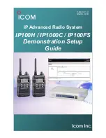
IP100H
Brand: Icom Pages: 57

DXi 50 WL
Brand: Scott Pages: 14

usb box
Brand: perfect pro Pages: 177

A1101R09 Series
Brand: Anaren Pages: 26

22 Ch GMRS/FRS Two-way Radios
Brand: Radio Shack Pages: 28

D-ONE BT
Brand: Zodiac Pages: 31

MR F80B
Brand: Cobra Marine Pages: 44

EDACS FMD
Brand: Ericsson GE Pages: 16

HP-51DFJ
Brand: Clas Ohlson Pages: 28

ATS-200
Brand: Olywiz Pages: 9

KH 75
Brand: EBENCH Pages: 10

CS-1000DX
Brand: Comtex Pages: 24

UH039P
Brand: Uniden Pages: 12

HAV-SR20
Brand: König Electronic Pages: 8

FR-314
Brand: Audiovox Pages: 30

IR706
Brand: AWA Pages: 28

NRC-160
Brand: Naxa Pages: 2

MD 43386
Brand: ALDI Pages: 32


