background image

KDL-42W650A 12

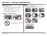
SECTION 3 - REPAIR INFORMATION

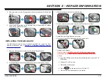
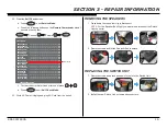
REPAIRING THE TV

If the latest Software does not correct the issue, complete the following:

1.  Verify the television has the symptom the customer indicated.

2.  Replace part causing the symptom. 

3.  Install the latest version of Software (Required for ALL repairs).

4.  Perform the required service adjustments and checks.

5.  Verify the repair resolved the issue.

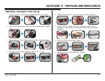
REMOVING THE TABLE-TOP STAND

1.  Remove 2 screws from Chassis Box and pull down as shown to detach. 

REMOVING THE CHASSIS BOX

1. 

Remove 1 screw from Bracket Top. Using a flat plastic object, separate 

bracket and grasp as shown to detach.

2.  Locate and disconnect connectors.

3.  Press down the 2 locking clips and pull LVDS cable to release.

4.  Locate and remove screws.


CAUTION: Do not use the Table-Top Stand 
to hold or carry the TV.

Summary of Contents for Bravia KDL-42W650A

Page 1: ...lor TV 9 883 551 02 RB1G Chassis Segment LW Version Date Subject 1 0 10 15 2013 Original Manual Release Date 2 0 12 16 2013 Updated Section 3 Repair Information Replaced page 13 Updated Section 5 OptionalAccessory included Replaced page 24 MODEL COMMANDER DESTINATION KDL 42W650A RM YD089 CND KDL 42W650A ...

Page 2: ...chart 8 Standby LED Blinking Flowchart 9 No Video Flowchart 10 Video Distortion Flowchart 11 Section 3 Repair Information 12 Repairing the TV 12 Removing the Table Top Stand 12 Removing the Chassis Box 12 Replacing the Main Board 13 Removing the Speakers 16 Replacing the Switch Unit 16 Removing the Smart Core Block 17 Section 4 Exploded View Part Number Information 18 KDL 42W650A 18 Smart Core Blo...

Page 3: ... CAUTIONS AND WARNINGS ATTENTION Ces instructions de service sont à l usage du personnel de service qualifié seulement Pour prévenir le risque de choc électrique ne pas faire l entretien autre que celui contenu dans le Mode d emploi à moins que vous soyez qualifié faire ainsi ALERTE Afin d eviter tout risque d electrocution provenant d un chássis sous tension un transformateur d isolement doit etr...

Page 4: ...eakage as described in Leakage Test LEAKAGE TEST The AC leakage from any exposed metal part to earth ground and from all exposed metal parts to any exposed metal part having a return to chassis must not exceed 0 5 mA 500 microamperes Leakage current can be measured by any one of three methods 1 A commercial leakage tester Follow the manufacturers instructions provided with the tester 2 A battery o...

Page 5: ...or this TV Refer to the i Manual for supported formats USB DLNA SECTION 1 SPECIFICATIONS AND LAYOUTS Screen size dimensions and mass are approximate values Optional accessories availability depends on countries region TV model stock Design and specifications are subject to change without notice Model name KDL 42W650A Power and others Power requirement Rating Input 110 240 V AC 50 60 Hz USA Canada ...

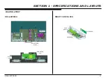
Page 6: ...KDL 42W650A 2 SECTION 1 SPECIFICATIONS AND LAYOUTS BOARD LAYOUT KDL 42W650A LD BOARD SMART CORE BLOCK HSC BOARD WLAN MODULE HIR BOARD SMART CORE BLOCK SWITCH UNIT MAIN BOARD BLX ...

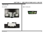
Page 7: ...KDL 42W650A 3 SECTION 1 SPECIFICATIONS AND LAYOUTS WIRE DRESSING KDL 42W650A SMART CORE BLOCK ...

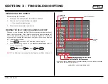
Page 8: ...ISPLAY Channel 5 Volume POWER NOTE This differs from accessing Service Adjustments Mode Volume SECTION 2 TROUBLESHOOTING SelfDiagnosis Supported model SELF CHECK 000 RESERVED 00 000 RESERVED 00 002 MAIN_POWE 00 003 DC_ALERT 00 003 AUD_PROT 00 003 HDMI_EQ 00 003 TU_DEMOD 00 004 VLED 00 004 LD_ERR 00 005 HFR_ERR 00 005 TCON_ERR 120123132522 120123113645 02 005 P_ID ERR 00 006 BACKLITE 00 007 TEMP_ER...

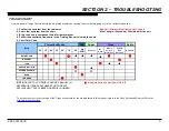
Page 9: ... Power Audio 2X 3X 4X 5X 6X 7X 8X No WIFI Dead set No Video Whole Screen Distortion Isolated Area Distortion No Audio MAIN BOARD LCD PANEL TCON SERVICE BULLETIN SOFWARE UPDATE WLAN Video Protection Modes 4 Follow the associated flowcharts in the Training Manual to isolate the board Board Immediate Shutdown After Power ON 7X NOTE REFER TO LCD PANELS SERVICE MANUAL IN REFERENCE LIBRARY DATABASE FOR ...

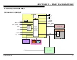
Page 10: ...VBS COMP VIDEO 1 CVBS RF HDMI 1 SWITCH UNIT LCD PANEL HFR TCON BLX L R HEAD PHONES OUT OPTICAL AUDIO OUT IC4601 AMP IC5009 HDMI SWITCH EQ TUNER ETHERNET USB HDMI 2 LVDS AC IN IC9000 A V DECODER VIDEO PROCESS LED BACKLIGHTS AC ADAPTOR WIFI IR RX LED s HIR HSC SMART CORE LD MAIN BOARD LOCAL DIMMING ...

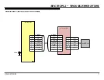
Page 11: ...5V GND PWM_DIMMER 1 2 5 3 4 VLED LD_STBY 6 7 LD_MODE_SW DC_DIMMER 8 9 CN8202 CN1001 LD BLX 10 LD_ERR 1 3 4 5 6 7 8 9 10 IP_REF LD_MODE_SW LD_STBY FB_REF PWM VCC_IN GND LD_ERR 2 DC IN LED 1 LED 2 LED 3 1 3 2 LED 4 NC 4 5 10 LED_VCC 11 14 LED BACKLIGHTS MAIN BOARD LOCAL DIMMING ...

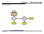
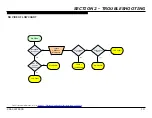
Page 12: ... No Power Yes No See protection flowchart Does TV turn ON Is red light blinking on front of TV Yes No AC Adaptor Substitute 19 5V AC Adaptor with another Main Board For Part Number information refer to Section 4 Exploded View Part Number Information on page 18 ...

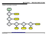
Page 13: ... Shutdown Standby LED Blinking No Yes No Yes 2X Main Board 3X 4X N A No 5X Yes 6X No 7X Immediately TCON LCD Panel Yes No After a while Main Board Check ventilation LD Board Main Board For Part Number information refer to Section 4 Exploded View Part Number Information on page 18 ...

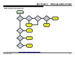
Page 14: ...ned on SONY logo appears momentarily No Main Board No Yes Yes Locate CN8202 on Main Board Zero volts at Pin 5 TCON LCD Panel Yes No Yes Main Board No LCD Panel LCD Panel Zero volts at Pin 1 For Part Number information refer to Section 4 Exploded View Part Number Information on page 18 ...

Page 15: ... Yes Improper or missing colors Yes Main Board No Vertical lines or bars No Yes Lines move when wide mode changed Yes No TCON LCD Panel Main Board LCD Panel Any single or isolated vertical lines Yes LCD Panel More than 1 vertical band No Yes TCON LCD Panel For Part Number information refer to Section 4 Exploded View Part Number Information on page 18 ...

Page 16: ...orm the required service adjustments and checks 5 Verify the repair resolved the issue REMOVING THE TABLE TOP STAND 1 Remove 2 screws from Chassis Box and pull down as shown to detach REMOVING THE CHASSIS BOX 1 Remove 1 screw from Bracket Top Using a flat plastic object separate bracket and grasp as shown to detach 2 Locate and disconnect connectors 3 Press down the 2 locking clips and pull LVDS c...

Page 17: ...est Software into one of the TVs USB ports b Connect TV to AC power c Wait at least 20 seconds d Press POWER on the remote to turn ON the TV e Wait until the Software update is complete 5 After removing screws firmly grasp as shown to separate Chassis Box from TV 6 Grasp and pull upwards on left and right side of Chassis Box to release clips Lift it upwards to detach REPLACING THE MAIN BOARD The M...

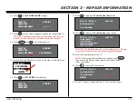
Page 18: ...ompleted CAUTION TV will turn ON and OFF during this process 15 After 5 minutes turn TV ON wait for a successful update screen to display and remove the USB device 16 Turn TV OFF again 17 Access Service Mode by pressing the following buttons within 1 second of each other DISPLAY Channel 5 Volume POWER 18 When the DIGITAL Menu appears press 2 until 002 MODEL category displays 19 Press 1 until 001 D...

Page 19: ...ays DIGITAL SERVICE 002 MODEL 003 SERIAL 27 Press 0 to display the Serial Number Edit option DIGITAL MODEL SERVICE SerialNumberEdit 1 SerialNumber 28 Press to display the Serial Number input screen DIGITAL MODEL SERVICE SerialNumberEdit 1 SerialNumber Please Input serial number 0000000 99999999 _ _ _ _ _ _ _ CAUTION The Serial Number can only be selected once Be sure to verify the information is c...

Page 20: ... 006 BACKLITE 00 007 TEMP_ERR 00 007 FAN_ERR 00 010 EMITTER 00 101 VPC_WDT 00 102 MEPS_WDT 00 103 HOST_WDT 00 104 STBY_WDT 00 00345 000333 06789 Error Count c To clear the error history and error count press 8 0 d Press POWER to exit Self Check Mode 33 Cycle AC Power Unplug and plug AC Cord from the outlet REMOVING THE SPEAKERS 1 Press down the connector clip to disconnect NOTE For the Speaker Box...

Page 21: ... of Cover SC and pull it apart to detach 4 Disconnect connectors and release cable from Lid SC hook 5 Unclamp 2 side clips from the Lid SC and lift as shown to detach LID SC 6 Carefully using a flat edge object ex steel ruler release the clip located on the right side corner and pull as shown to detach the Panel Ornament 7 Detach the HIR Board and WLAN Module HIR BOARD WLAN MODULE 8 Release hooks ...

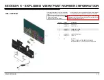
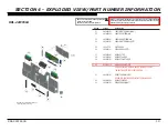
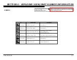
Page 22: ...The components identified by a red outline and a mark contain confidential information Specific instructions must be adhered to whenever these components are repaired and or replaced See Appendix A KDL 42W650A 1 4 462 165 01 STAND NECK 2 4 460 953 01 STAND PIPE ML 3 1 838 955 41 POWER SUPPLY CORD 4 1 492 293 12 AC ADAPTOR 120W 5 4 446 865 02 CHASSIS BOX 42 MMB 6 4 446 122 01 COVER SC 7 NA LCD PANE...

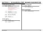
Page 23: ...8 882 02 LABEL REAR TERMINAL 53 4 458 888 01 LABEL UNDER TERMINAL 54 4 458 885 01 LABEL SIDE TERMINAL LEFT 55 1 492 117 11 SWITCH UNIT 56 1 858 861 11 SPEAKER BOX LEFT 57 4 439 638 01 BRACKET TOP 58 4 439 636 01 BRACKET UNDER 59 4 439 637 03 BRACKET SIDE TUNER 60 A 1923 827 A BLX BOARD COMPLETE AFTER REPLACING THE MAIN BOARD YOU MUST UPDATE THE SOFTWARE TO THE LATEST VERSION 61 4 440 057 01 SHEET ...

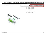
Page 24: ... outline and a mark contain confidential information Specific instructions must be adhered to whenever these components are repaired and or replaced See Appendix A 101 1 492 076 11 WLAN MODULE 102 A 1906 604 B HSC WIFI BOARD MOUNTED 103 4 454 489 03 CASE SC 104 A 1924 408 A HIR BOARD MOUNTED 105 4 451 771 02 PANEL ORNAMENT SC 106 4 446 121 01 LID SC REF NO PART NO DESCRIPTION 104 105 106 102 103 1...

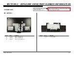
Page 25: ...ed outline and a mark contain confidential information Specific instructions must be adhered to whenever these components are repaired and or replaced See Appendix A CONNECTORS REF NO PART NO DESCRIPTION 151 1 910 803 51 CONNECTOR ASSEMBLY 10P 152 1 910 803 48 CONNECTOR ASSEMBLY 20P 153 1 846 625 21 LVDS FFC WITH CONNECTOR 51P 201 1 910 803 53 HARNESS ASSEMBLY REF NO PART NO DESCRIPTION 201 151 15...

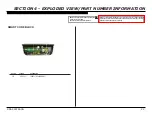
Page 26: ...fety Replace only with part number specified NOTE The components identified by a red outline and a mark contain confidential information Specific instructions must be adhered to whenever these components are repaired and or replaced See Appendix A SMART CORE BLOCK 251 251 1 910 803 21 CONNECTOR ASSEMBLY 5P REF NO PART NO DESCRIPTION ...

Page 27: ...ctions must be adhered to whenever these components are repaired and or replaced See Appendix A SCREWS 4 159 298 01 SCREW PSW M4X10 2 990 421 41 SCREW PSW M3X6 SCREW PSWTP2 4X10 7 685 647 79 SCREW BVTP 3X10 TYPE2 IT 3 4 462 169 01 SCREW M4X8 LOCK Main Board 5 Table Top Stand to TV 2 Chassis Box 4 Chassis Box 5 Switch Unit 2 Smart Core Block 1 Speaker Box Right 2 Speaker Box Left 2 Stand Neck 2 P N...

Page 28: ...W M4X10 ATTACHMENT PARTS FOR WALL MOUNT BRACKETS 4 462 084 11 MANUAL INSTRUCTION ENGLISH VERSION 4 462 084 21 MANUAL INSTRUCTION FRENCH VERSION 4 262 708 04 CLAMPER CABLE 4 460 156 01 WALL MOUNT BKTASSEMBLY MISCELLANEOUS PART NO DESCRIPTION 7 600 031 97 TAPE 3M 1350FB 1 15MMX66M BLK 7 600 031 96 TAPE 3M 1350FW 1 15MMX66M WHT 3 299 071 06 FLYER SAFETY OPTIONAL ACCESSORIES PART NO DESCRIPTION 4 414 ...

Page 29: ...key components shall be identified with a red outline and a 2 Only repair boards or components listed in the service manual shall be utilized for replacement and or repair 3 Disassembly decryption or reverse engineering component s is strictly prohibited 4 Any board in which the Servicer replaces an encryption key component must be placed back into the set it orignally came from and the replaced d...

Reviews: