Sony BKM-16R Operation Manual Download Page 6

6

Location and Function of Parts

Location and Function of Parts

For functions available with your monitor, see page 5.
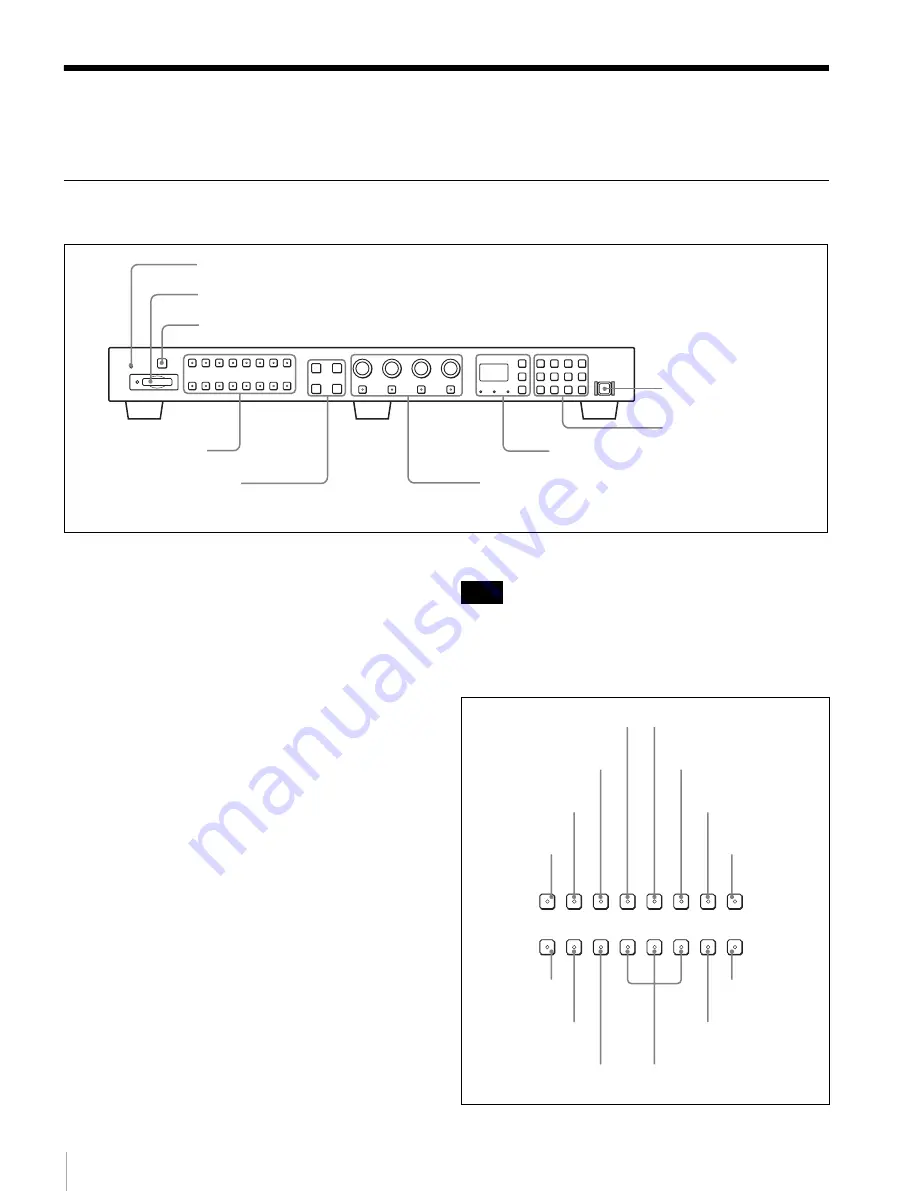
Front Panel

a

OPERATE lamp

The lamp lights when the unit is turned on.

b

Memory Stick insertion slot

The standard and duo type “Memory Stick” is available. 
Insert the “Memory Stick” (optional).
When you use a “Memory Stick Micro”, do so after 
attaching the M2 adaptor (optional).

For inserting/ejecting the “Memory Stick”, see page 10.

The setting and adjustment data saved in the “Memory 
Stick” are only compatible with monitors of the same 
series.
It is not possible to load the data stored in the “Memory 
Stick” inserted in this slot to a monitor that does not 
support the “Memory Stick,” or save the setting/adjustment 
data in the “Memory Stick” inserted in this slot to such a 
monitor.

c

CAPTURE button

Press to capture the 3G/HD-SDI input signal as the still 
picture in frame.

d

Function buttons

Press to change the operation conditions for the monitor.
Each time the button is pressed, the LED on the button 
turns on and turns off, and the operation conditions are 
changed.  (The LED may not turn on depending on the 
function.)

You can assign other functions to the F1 to F16 buttons.

The button may not function due to the input signal.  For 
the limitations with each type of signal, refer to the manual 
of your monitor.

Factory preset setting

2

 Memory Stick insertion slot

4

 Function buttons

5

 Menu operation buttons

6

 MONITOR I/

1

 switch

7

 Numeric keypad

8

 Monitor selection buttons and lamps

9

 MANUAL adjustment buttons and knobs

1

 OPERATE lamp

3

 CAPTURE button

Note

APT

COMB

CHAR

OFF

COL

TEMP

16 : 9

NATIVE

SCAN

BLUE
ONLY

R OFF

G OFF

B OFF MARKER

F4

F5

F6

F7

CHROMA

UP

F2

F3

F8

F12

F13

F14

F15

F10

F11

F16

MONO

H DELAY V DELAY

SCAN

F9

F1

SCAN button

MONO button

APT button

COMB button

CHAR OFF button

COL TEMP button

R, G, B OFF buttons

MARKER button

CHROMA UP 
button

BLUE ONLY button

NATIVE SCAN button

16:9 button

H DELAY button

V DELAY button

Summary of Contents for BKM-16R

Page 1: ...MONITOR CONTROL UNIT BKM 16R OPERATION MANUAL English 1st Edition Revised 3 ...

Page 2: ...interference at his own expense You are cautioned that any changes or modifications not expressly approved in this manual could void your authority to operate this equipment All interface cables used to connect peripherals must be shielded in order to comply with the limits for a digital device pursuant to Subpart B of Part 15 of FCC Rules This device complies with Part 15 of the FCC Rules Operati...

Page 3: ...ons 5 Location and Function of Parts 6 Front Panel 6 Rear Panel 9 Inserting Ejecting the Memory Stick 10 Notes on Memory Stick 10 Mounting the Unit in a Rack 12 Connections 12 Connecting the Monitor 12 Connecting the Multiple Units with the LAN 13 Specifications 14 Dimensions 15 ...

Page 4: ...l connected monitors or put all connected monitors into the same setup and adjustment state Setup and adjustment with the Memory Stick You can use a Memory Stick to save and load monitor setup and adjustment data If your system includes more than one monitor you can use the Memory Stick to exchange data between monitors This makes it easy to put all monitors in your system into the same setup and ...

Page 5: ...dently Monitor BVM A series BVM series except BVM A PVM L series PVM series except PVM L Available function Setup adjustment with Memory Stick a a a a CAPTURE a a Function assignment to function buttons a b a b SCAN a a a a H DELAY a a a a c V DELAY a a a a c MONO a a a a APT a a a Aperture modification adjustment a a a a COMB a a a CHAR OFF a a a COL TEMP a a a a 16 9 a a a a NATIVE SCAN a a a BL...

Page 6: ...n frame d Function buttons Press to change the operation conditions for the monitor Each time the button is pressed the LED on the button turns on and turns off and the operation conditions are changed The LED may not turn on depending on the function You can assign other functions to the F1 to F16 buttons The button may not function due to the input signal For the limitations with each type of si...

Page 7: ... button Press to cut R red G green and B blue respectively MARKER button Press to display all markers on the screen The marker display mode is set in the menu of the monitor CHROMA UP button Press to increase the chroma setting by 12 dB e Menu operation buttons f MONITOR I 1 switch Each time the switch is pressed the monitor is turned on or set in standby mode When several monitors are connected t...

Page 8: ... monitor SINGLE SINGLE REMOTE GROUP ALL GROUP ALL SINGLE button Selects single connection mode The designated monitor is connected remotely The monitor ID number is displayed on all connected monitors when the button is held pressed GROUP button Selects group connection mode The monitor of the designated group is connected remotely The group ID number is displayed on all connected monitors when th...

Page 9: ...able of the unit to peripheral device use a shielded type cable to prevent malfunction due to radiation noise To connect the unit to the LAN 10 100 connector of the monitor in 1 to 1 connection NETWORK switch is set to PEER TO PEER use a straight shielded type cable The connection speed may be affected by the network system b DC 5V 12V IN connector male Connect to the DC 5V OUT connector of the mo...

Page 10: ... the Memory Stick in the correct direction Forcing the Memory Stick in the wrong way may damage it Insert only the Memory Stick into the Memory Stick insertion slot Attempting to insert other objects into the Memory Stick insertion slot may damage the product To eject the Memory Stick Notes on Memory Stick Available types of Memory Stick Memory Stick Memory Stick PRO Memory Stick Duo Memory Stick ...

Page 11: ... at the same time This may cause damage to the product When you use Memory Stick Duo Memory Stick PRO Duo with this product be sure to insert it in the right direction Inserting it in the wrong direction may cause damages to the product Memory Stick Duo Memory Stick PRO Duo Memory Stick Micro and M2 adaptor should be kept away from small children to prevent them from accidentally swallowing it If ...

Page 12: ...ze of the rack s holes Connections The illustrations of the monitor used in this manual are BVM E250 Note on connecting the cable to the DC 5V 12V IN connector Be sure to plug the female connector of the cable into the DC 5V 12V IN connector on the unit Connect the connector to the shape of the DC 5V 12V IN connector Connecting the Monitor Rack mount bracket BKM 16R this unit Rack mount attachment...

Page 13: ...ing the Multiple Units with the LAN The unit controls up to 32 monitors Up to four units are connected to one monitor in single mode The unit cannot control monitors in another subnetwork 1 Turn off the MAIN POWER switch of the monitor before connecting the units 2 Connect to the network by using a 10BASE T 100BASE TX cable shielded type optional When an optional LAN cable is connected use a shiel...

Page 14: ... 100 240 V 50 60 Hz DC OUT 12 V 3 A Current consumption 5 V DC 1 1 A 12 V DC 0 5 A Power consumption Approx 6 W Peak inrush current 1 Power ON current probe method 20 A 100 V 60 A 240 V 2 Hot switching inrush current measured in accordance with European standard EN55103 1 10 A 230 V Operating temperature 0 C to 35 C 32 F to 95 F Recommended 20 C to 30 C 68 F to 86 F Operating humidity 0 to 90 no c...

Page 15: ...MEDIA EXTERNAL STORAGE SYSTEMS OR ANY OTHER MEDIA OR STORAGE SYSTEMS TO RECORD CONTENT OF ANY TYPE Always verify that the unit is operating properly before use SONY WILL NOT BE LIABLE FOR DAMAGES OF ANY KIND INCLUDING BUT NOT LIMITED TO COMPENSATION OR REIMBURSEMENT ON ACCOUNT OF THE LOSS OF PRESENT OR PROSPECTIVE PROFITS DUE TO FAILURE OF THIS UNIT EITHER DURING THE WARRANTY PERIOD OR AFTER EXPIR...

Page 16: ... for use by the purchasers of the equipment described in this manual Sony Corporation expressly prohibits the duplication of any portion of this manual or the use thereof for any purpose other than the operation or maintenance of the equipment described in this manual without the express written permission of Sony Corporation ...

Page 17: ...Sony Corporation BKM 16R WW 3 213 868 14 1 2008 ...

Reviews: