24
Chapter 4:
Setup and Operation
Setup Security Settings
Security Setup
SonoSite provides a comprehensive set of tools on the system that allows its customers to meet the applicable
security requirements listed in the HIPAA standard. SonoSite's customers are ultimately responsible for ensuring
the security and protection of all electronic protected health information collected, stored, reviewed, and
transmitted on the system.
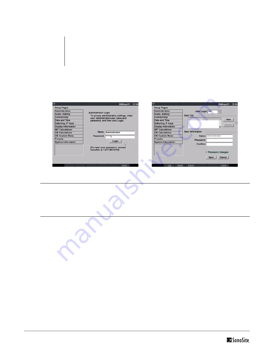
Figure 5 Setup Screens: Administration and Administrator Information
WARNING:
Health care providers who maintain or transmit health information are required by the Health
Insurance Portability and Accountability Act (HIPAA) of 1996 and the European Union Data
Protection Directive (95/46/EC) to implement appropriate procedures: to ensure the integrity and
confidentiality of information; to protect against any reasonably anticipated threats or hazards to
the security or integrity of the information or unauthorized uses or disclosures of the information.
Administrator Login
1
Press the
Setup
key.
2
Select Administration.
3
In Administrator Login, type Administrator in the Name field.
4
Call SonoSite for the password (1-877-657-8118).
5
Select Login.
Change Administrator
Password
1
In User Information, enter your new password in the Password field.
2
Enter the password again in the Confirm field.
To ensure passwords are secure, it is recommended that passwords contain
characters from the following categories:
• Upper case characters: A-Z
• Lower case characters: a-z
• Numbers: 0-9
Note: The password is case-sensitive.
3
In Password changes, click on the check box to allow users access to change
their password or leave unchecked to restrict access. (Optional)
4
Select Save.
Summary of Contents for MicroMaxx
Page 1: ...MicroMaxx Ultrasound System Service Manual ...
Page 6: ...vi ...
Page 10: ...4 Chapter 1 Introduction ...
Page 56: ...50 Chapter 5 Cleaning and Disinfecting ...
Page 61: ...Chapter 6 Troubleshooting 55 Control Panel Figure 6 3 Control Panel Flow Diagram ...
Page 62: ...56 Chapter 6 Troubleshooting System Figure 6 4 System Flow Diagram ...
Page 63: ...Chapter 6 Troubleshooting 57 Battery Figure 6 5 Battery Flow Diagram ...
Page 72: ...66 Chapter 7 Replacement Procedures Figure 7 10 Power Supply Screws Screws 7 ...
Page 85: ...Appendix A Parts List 79 Figure A 1 Power Supply P05471 Figure A 2 Speaker Assembly P03872 ...
Page 89: ...Appendix A Parts List 83 Figure A 8 Main PCB Assembly P05472 ...
Page 92: ...86 Appendix B Service Event Report ...
Page 98: ...92 Index ...


