


II-73
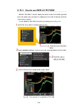
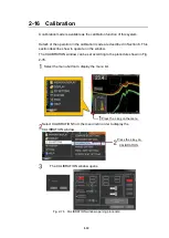
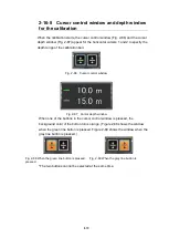
2-16-3
Screen structure at the start of the
calibration
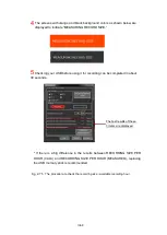
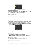
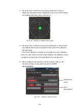
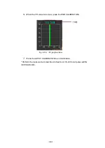
Press the CALIBRATION START button on the screen shown in Fig. 2-77. Then,
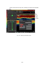
the screen shown in Fig. 2-79 will be displayed. This screen is composed of the
echogram window, the calibration control window, the calibration trace graph
window, the TR graph window and the cursor display window.
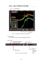
Two horizontal cursors are also displayed to specify both start and final depths
for narrowing down the position of the calibration ball.
*Note 1) When more than one ES have been displayed on the screen, only the
ES to be calibrated will be displayed.
*Note 2) When the fish length graph and the trace graph of the ES to be calibrated
are displayed on the screen, this screen will be closed.
*Note 3) Even if the menu button is pressed in the calibration mode, all menu
items are disabled.
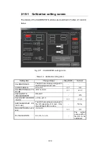
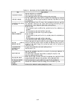
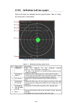
Fig. 2-79 Screen structure after the start of calibration
Calibration trace graph window Cursor display window
CALIBRATION CONTROL window
TR graph window
Echogram window
Summary of Contents for KSE-310
Page 1: ...KSE 310 TYPE FISH SIZING ECHO SOUNDER Instruction Manual Ver 5 04E SONIC CORPORATION ...
Page 2: ... MEMO ...
Page 163: ...III 153 ...
Page 166: ...III 156 3 2 1 CURSOR CONTROL This is described in Section 2 9 ...
Page 186: ...Ⅲ IV 14 Fig 4 13 NET DEPTH Display Method dialog ...
Page 196: ......


