


17
INTERCOM OPERATION
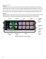
VOLUME CONTROLS (ALL MODELS):
VOLUME INDICATOR
The Volume Indicator is a vertical row of 10 colored LED’s. Minimum volume is indicated by only the bottom yellow
indicator being lit. Maximum volume is indicated by all 10 LED’s being lit.
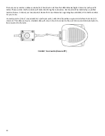
Master headset volume is set with the front
face volume pad.
IMPORTANT:
When power is turned off to the intercom, the intercom and Remote Intercoms remember the last volume
setting and will return to that volume level when power is turned on again.
VOLUME UP BUTTON (ALL MODELS)
Pressing this button once increases the intercom volume by one step. After pressing the button three times one more
LED in the Volume Indicator lights. Once maximum volume has been reached (all LED's in the Volume Indicator are lit),
pressing the Volume Up Button will have no effect.
VOLUME DOWN BUTTON (ALL MODELS)
Pressing this button once decreases the intercom volume by one step. After pressing the button three times, one less
LED in the Volume Indicator lights. Once minimum volume has been reached (only the bottom LED in the Volume
Indicator is lit), pressing the Volume Down Button will have no effect.
The minimum volume level is not zero volume. It is NOT possible to turn the intercom audio off using the Volume
Control Buttons.
The Volume Controls on the SON200 Series Digital Intercoms adjust the volume of INTERCOM COMMUNICATION
ONLY! The Volume Controls DO NOT adjust the volume of the Receive Audio from the radio(s). To adjust the volume
of the Receive Audio, adjust the Receive Audio Adjustment or the radio's volume control.
INTERCOM ADJUSTMENTS AND OPERATIONS:
For the Radio, Aux, and Cell connections to the intercom the user can adjust input gain and output gain to allow
interfacing the intercom to other equipment.
It is important to set your device gain levels appropriately for your connected equipment.
•
An input gain that is too low results in insufficient volume level.
•
An output gain that is too low causes insufficient volume level in your end device.
•
An output gain that is too high results in audio distortion caused by clipping in your output device.
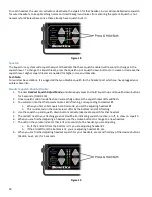
PROGRAMMING INPUT AND OUTPUT DEVICE GAIN
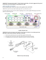
1.
To enter
Device Gain Adjust Mode
, simultaneously press and hold Volume up and Volume down buttons for 5
seconds. (FIGURE 18)
2.
Once Device Gain Adjust Mode has been successfully entered, the Volume level LEDs and the Squelch level LEDs
will flash.
3.
Press the button corresponding to the device you want to adjust, for example, Radio 1.
4.
Note that the Blue and Green LEDs on the Radio 1 button will begin to flash.
5.
Use the Volume up and down buttons to adjust input gain to the desired setting
o
Have a coworker transmit to you over the radio
o
Adjust input gain until his voice is at the level you want it to be.
6.
Use the Squelch up and down buttons to adjust output gain to the desired setting
o
Pressing the PTT button on your headset, transmit over the radio to your coworker
o
Adjust output gain until your audio level is where your coworker wants it to be.
7.
To adjust another Radio or Aux, repeat Steps 3-6.
8.
When you are finished adjusting input and output gains for your device, press and hold any of the device
buttons (Radio1, Aux1, etc.) for 5 seconds.