background image

CMM-40 

– INSTRUKCJA OBSŁUGI 

Opis funkcjonalny 

4.1  Gniazda  pomiarowe  i  elementy  wyboru  funkcji  po-

miarowej 


CMM-40 

Summary of Contents for CMM-40

Page 1: ...INSTRUKCJA OBS UGI 1 USER MANUAL 39 MANUAL DE USO 73 CMM 40 v1 6 19 10 2018...

Page 2: ......

Page 3: ...1 INSTRUKCJA OBS UGI MULTIMETR PRZEMYS OWY CMM 40 Wersja 1 6 19 10 2018...

Page 4: ...CMM 40 nale automatyczna lub r czna zmiana zakres w funkcja HOLD umo liwiaj ca odczyt pomiar w przy niedosta tecznym o wietleniu lub w trudno dost pnych miejscach funkcja REL umo liwiaj ca dokonywani...

Page 5: ...emiennego 15 5 3 Pomiar napi cia w mV 16 5 4 Pomiar pr du sta ego 17 5 5 Pomiar pr du przemiennego cz stotliwo cykl roboczy 18 5 6 Pomiar rezystancji 19 5 7 Test ci g o ci obwodu 19 5 8 Test diod 20 5...

Page 6: ...uracja parametr w 27 6 11 AC DC 27 7 Wymiana baterii 28 8 Wymiana bezpiecznik w 29 9 Utrzymanie i konserwacja 30 10 Magazynowanie 31 11 Rozbi rka i utylizacja 31 12 Za czniki 32 12 1 Dane techniczne 3...

Page 7: ...ia je eli nie przestrzega si instrukcji S owo UWAGA rozpoczyna opis sytuacji w kt rej niezastoso wanie si do instrukcji grozi uszkodzeniem przyrz du OSTRZE ENIE Miernik CMM 40 jest przeznaczony do pom...

Page 8: ...ie nale y prze cza urz dzenia w tryb pomiaru pr du lub rezystancji nie wolno przekracza maksymalnego dopuszczalnego zakresu napi cia wej ciowego dla adnej funkcji nie wolno pod cza napi cia do miernik...

Page 9: ...tych warun kach mo e wywo a iskrzenia i spowodowa eksplozj UWAGA Warto ci graniczne sygna u wej ciowego Funkcja Maksymalna warto wej ciowa V DC lub V AC 1000V DC AC rms mA AC DC Bezpiecznik szybki 50...

Page 10: ...ecznych napi Podw jna izolacja 3 Przygotowanie miernika do pracy Po zakupie miernika nale y sprawdzi kompletno zawarto ci opakowania Przed przyst pieniem do wykonywania pomiar w nale y upewni si e sta...

Page 11: ...CMM 40 INSTRUKCJA OBS UGI 9 4 Opis funkcjonalny 4 1 Gniazda pomiarowe i elementy wyboru funkcji po miarowej CMM 40...

Page 12: ...zystkich funkcji pomiaro wych 9 gniazdo pomiarowe CAPV F CHz Wej cie pomiarowe dla pozosta ych pomiar w opr cz pr d w 4 1 2 Elementy wyboru funkcji pomiarowej 1 wy wietlacz LCD 2 STORE RECALL Wpis wyn...

Page 13: ...ony VACHz pomiar napi cia przemiennego cz stotliwo ci cyklu roboczego VDC pomiar napi cia sta ego mV pomiar napi cia sta ego i przemiennego do 400mV Hz pomiar cz stotliwo ci cyklu roboczego wype nie n...

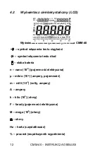
Page 14: ...iernika CMM 40 symbol w czenia testu ci g o ci symbol w czenia testu diod s aba bateria n nano 10 9 pojemno elektryczna mikro 10 6 ampery pojemno m milli 10 3 volty ampery A ampery k kilo 103 ohmy F f...

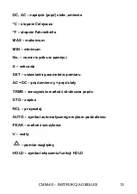
Page 15: ...maksimum MIN minimum No numer wyniku w pami ci S sekunda SET ustawianie parametr w pomiaru AC DC pr d zmienny pr d sta y TRMS rzeczywista warto skuteczna pr du STO zapisz RCL przywo aj AUTO symbol aut...

Page 16: ...ie nale y mierzy napi cia sta ego w momencie gdy silnik elektryczny w obwodzie jest w czany lub wy czany Mog o by to spowodowa du e skoki napi cia i w rezultacie uszko dzenie miernika Aby wykona pomia...

Page 17: ...si pod napi ciem UWAGA Nie nale y mierzy napi cia przemiennego w momencie gdy silnik elektryczny w obwodzie jest w czany lub wy czany Mog oby to spowodowa du e skoki napi cia i w rezultacie uszkodzeni...

Page 18: ...o by to spowodowa du e skoki napi cia i w rezultacie uszko dzenie miernika ustawi prze cznik obrotowy w pozycji mV nacisn przycisk MODE w celu wy wietlenia warto ci DC lub AC w zakresie AC nacisn przy...

Page 19: ...r du do 400mA DC nale y ustawi prze cznik funkcji w po o eniu mA i pod czy czerwony przew d pomia rowy do gniazda A mA dla pomiar w pr du do 20A DC nale y ustawi prze cznik funkcji w po o eniu 10AHz i...

Page 20: ...20A AC nale y ustawi prze cznik funkcji w po o eniu 10AHz i pod czy czerwony przew d pomiarowy do gniazda 10A nacisn przycisk MODE w celu wy wietlenia warto ci AC na wy wietlaczu od czy zasilanie od p...

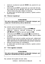
Page 21: ...tawi prze cznik obrotowy w pozycji CAP pod czy czerwony przew d pomiarowy do gniazda CAPV F CHz a czarny do gniazda COM nacisn przycisk MODE aby wy wietli na wy wietlaczu w razie potrzeby przyciskiem...

Page 22: ...cym pod napi ciem Kondensatory nale y roz adowa Aby wykona test diody nale y ustawi prze cznik obrotowy w pozycji CAP pod czy czerwony przew d pomiarowy do gniazda CAPV F CHz a czarny do gniazda COM...

Page 23: ...czyta wynik pomiaru na wy wietlaczu po zako czeniu pomiar w wyj przewody z gniazd pomiaro wych miernika 5 10 Pomiar temperatury Aby wykona pomiar nale y ustawi prze cznik obrotowy w pozycji Temp pod c...

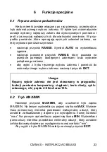
Page 24: ...F CHz a czarny do gniazda COM przy o y ostrza sond do testowanego obwodu w razie potrzeby przyciskiem RANGE ustawi r cznie zakres pomiarowy odczyta wynik pomiaru na wy wietlaczu nacisn przycisk MODE a...

Page 25: ...az wybranie po danego zakresu aby wyj z trybu r cznego wyboru zakresu i powr ci do automatycznego wyboru zakresu nacisn przycisk EXIT Uwaga R czny wyb r zakresu nie jest stosowany w przypadku funkcji...

Page 26: ...lewym wy wietlaczu pomocniczym pojawi si r nica warto ci warto bie ca pomiaru na prawym wy wietlaczu pomocniczym pojawi si odczyt pocz tkowy na wy wietlaczu g wnym przedstawiony zostanie odczyt pomia...

Page 27: ...dlatego zaleca si urucha mia funkcj dopiero po pod czenia przewod w do punktu pomiarowego Uruchomienie funkcji PEAK HOLD przed pod czeniem miernika do punktu mierzonego mo e powodowa wy wietlanie symb...

Page 28: ...k STORE aby rozpocz automatyczny zapis do pami ci W lewym g rnym rogu podawana jest aktualna kom rka pami ci zapisywane dane s wy wietlane w prawym g rnym rogu Uwaga Ze wzgl du na ograniczenia cyfrowe...

Page 29: ...aj ustawie Rodzaj ustawie obejmuje poni sze elementy w sekwencji A alarm d wi kowy dla g rnego limitu B alarm d wi kowy dla dolnego limitu C czas do automatycznego wy czenia zasilania D sygna d wi kow...

Page 30: ...iany baterii mo e spowodowa pora enie niebezpiecznym napi ciem Aby wymieni bateri nale y wyj przewody z gniazd pomiarowych i prze cznik obrotowy ustawi w pozycji OFF otworzy tyln pokryw baterii poprze...

Page 31: ...ieni bateri nale y wyj przewody z gniazd pomiarowych i prze cznik obrotowy ustawi w pozycji OFF otworzy tyln pokryw baterii poprzez odkr cenie dw ch rub B u ywaj c rubokr tu krzy akowego wyj bateri od...

Page 32: ...ERNIK NALE Y STOSOWA ORAZ PRZECHOWYWA W NORMALNYCH TEMPERATURACH Temperatury skrajne mog skr ci ywotno elektronicznych element w miernika oraz zniekszta ci lub stopi elementy plastikowe 3 Z MIERNIKIEM...

Page 33: ...rzestrzega poni szych zalece od czy od miernika przewody upewni si e miernik i akcesoria s suche przy d u szym okresie przechowywania nale y wyj bateri 11 Rozbi rka i utylizacja Zu yty sprz t elektryc...

Page 34: ...00 0V 0 1V 0 1 w m 5 cyfr Pomiar napi cia przemiennego True RMS Zakres Rozdzielczo Niepewno podstawowa 400 00mV 0 01mV 1 w m 40 cyfr 4 0000V 0 0001V 1 w m 30 cyfr 40 000V 0 001V 400 00V 0 01V 1000 0V...

Page 35: ...ej wilgotno ci powietrza ni szej ni 75 Dla pr du zniekszta conego b d jest wi k szy o 2 odczytu 2 pe nej skali dla wsp czynnika szczytu 3 0 Pomiar rezystancji Zakres Rozdzielczo Niepewno podstawowa 40...

Page 36: ...zego oraz 100kHz minimalna warto skuteczna napi cia 5V przy 20 do 80 cyklu roboczego oraz 100kHz Pomiar cz stotliwo ci w elektryce Zakres Rozdzielczo Niepewno podstawowa 40 00Hz 10 000kHz 0 01Hz 0 001...

Page 37: ...su 500V zmniejszaj cy si liniowo do 1 5 przy 1000V i warto szczytowa PEAK wychwytuje warto ci szczytowe 1ms j cz stotliwo pomiar w 2 odczyty na sekund k impedancja wej ciowa 10M V DC 9M V AC l wy wiet...

Page 38: ...atyczka zabezpieczaj ca gniazda pomiarowe 2 szt futera instrukcja obs ugi karta gwarancyjna 12 3 Serwis Prowadz cym serwis gwarancyjny i pogwarancyjny jest SONEL S A ul Wokulskiego 11 58 100 widnica t...

Page 39: ...lektrycznych Wzorcowane s nast puj ce typy przyrz d w mierniki do pomiar w wielko ci elektrycznych oraz para metr w sieci energetycznych o mierniki napi cia o mierniki pr du w tym r wnie mierniki c go...

Page 40: ...otwierdzenia metrologicznego nie rzadziej ni co 13 miesi cy Dla wprowadzanych do u ytkowania fabrycznie nowych przyrz d w posiadaj cych wiadectwo Wzorcowania lub Certyfikat Kalibracji kolejne wykonani...

Page 41: ...39 USER MANUAL INDUSTRIAL MULTIMETER CMM 40 Version 1 6 19 10 2018...

Page 42: ...C voltage measurements 52 5 3 mV voltage measurements 53 5 4 DC current measurements 54 5 5 AC current frequency duty cycle measurements 55 5 6 Resistance measurements 56 5 7 Continuity Measurements 5...

Page 43: ...g up function 63 6 11 AC DC function 63 7 Replacement of the batteries 64 8 Replacement of the fuses 65 9 Cleaning and maintenance 66 10 Storage 67 11 Dismantling and utilization 67 12 Attachments 67...

Page 44: ...esented in the present manual not be observed The word ATTENTION introduces a description of a situation where non observance of the recommendations presented in the present manual may imply damage fo...

Page 45: ...ho also must be trained regarding the industrial safety regulations Use great care when making measurements if the voltages are greater than 20VAC rms or 40VDC These voltages are consid ered a shock h...

Page 46: ...s with wet hands WARNING Do not realise measurements in environments in which there are inflammable gases Otherwise operation of the meter under such conditions may cause sparking and explosion ATTENT...

Page 47: ...he meter examine completeness of the con tents of the package Before measurements commence it is necessary to realise the fol lowing actions Make sure the conditions of the batteries or accumulators p...

Page 48: ...CMM 40 USER MANUAL 46 4 Functional description 4 1 Measurement sockets and elements of selection of the measurement function Illustration 1 CMM 40...

Page 49: ...measurement socket CAP V F C Hz Measurement socket for all the measurement functions ex cept of current measurements 4 1 2 Elements of selection of the measurement function 1 40 000 count LCD display...

Page 50: ...r off VACHz alternative voltage frequency and duty cycle measurement VDC direct voltage measurement mV direct and alternative voltage measurement up to 400mV Hz frequency and duty cycle measurement CA...

Page 51: ...ation 2 LCD display of the CMM 40 meter continuity check mode diode test mode Battery status n nano 10 9 capacitance micro 10 6 amps cap m milli 10 3 volts amps A Amps k kilo 103 ohms F Farads capacit...

Page 52: ...direct current C degrees Celsius F degrees Fahrenheit MAX maximum MIN minimum No serial number S second SET set up parameter AC DC alternating current direct current TRMS true RMS STO store RCL recall...

Page 53: ...age measurements ATTENTION Do not measure DC voltages if a motor on the circuit is being switched ON or OFF Large voltage surges may occur that can damage the meter In order to realise a measurement o...

Page 54: ...f AC voltage it is necessary to realise the following actions Set the function switch to the VAC Hz position with the RANGE button set the measurement range manually if necessary Insert the black test...

Page 55: ...with the RANGE button set the measurement range manually if necessary Press the MODE button to indicate DC or AC or in AC range press EXIT for two seconds and chose AC DC Insert the black test lead b...

Page 56: ...urrent measurements up to 400mA DC set the function switch to the mA position and insert the red test lead banana plug into the A mA jack For current measurements up to 20A DC set the function switch...

Page 57: ...jack For current measurements up to 20A AC set the function switch to the 10A HZ position and insert the red test lead banana plug into the 10A jack Press the MODE button to indicate AC on the displa...

Page 58: ...play Touch the test probe tips across the circuit or part under test It is best to disconnect one side of the part under test so the rest of the circuit will not interfere with the resistance reading...

Page 59: ...order to realise diode test it is necessary to realise the follow ing actions Set the function switch to the green CAP position Insert the black test lead banana plug into the negative COM jack and t...

Page 60: ...apacitor to be tested Read the capacitance value in the display Having done the measurement disconnect the test leads from the meter 5 10 Temperature measurements In order to realise temperature measu...

Page 61: ...s the MODE button to indicate Read the duty cycle in the display Having done the measurement disconnect the test leads from the meter 5 12 4 20 mA measurements In order to realise measurement it is ne...

Page 62: ...pear The right auxiliary display meter will display and hold the minimum reading and will update only when a new min occurs To exit MAX MIN mode press EXIT 6 3 Relative mode The relative measurement f...

Page 63: ...button for 2 s signal isation with a long sound After releasing the button the symbol PEAK will appear At the top of the display symbols will appear MAX in left auxiliary display MIN in right auxilia...

Page 64: ...recording Press the STORE button again to record once When the recording interval time is 1 255 S then press STORE button again to start recording automatically from 0000 or XXXX chosen earlier Record...

Page 65: ...into SET function Then press SET shortly once change on setting content Setting content includes in sequence A upper limit buzzer alarm B lower limit buzzer alarm C auto power off time D turn off phon...

Page 66: ...he battery there might be a risk of electric shock with a dangerous voltage WARNING To avoid electric shock do not operate the meter until the battery cover is in place and fastened securely Caution I...

Page 67: ...To avoid electric shock disconnect the test leads from any source of voltage before removing the meter cover In order to replace the fuses it is necessary to do the following Disconnect the test leads...

Page 68: ...R DRY If it gets wet wipe it off 2 USE AND STORE THE METER IN NORMAL TEMPERATURES Temperature extremes can shorten the life of the electronic parts and distort or melt plastic parts 3 HANDLE THE METER...

Page 69: ...ectively i e it must not be placed with waste of another kind Worn out electronic equipment should be sent to a collection point in accordance with the law of worn out electric and electronic equipmen...

Page 70: ...A 0 1 A 40 000mA 0 001mA 400 00mA 0 01mA 10 000A 0 001A 20A 30 sec max with reduced accuracy AC current measurement True RMS AC DC Range Resolution Basic uncertainty 400 00 A 0 01 A 1 5 m v 30 digits...

Page 71: ...3 5 m v 40 digits 400 00nF 0 01nF 4 0000 F 0 0001 F 3 5 m v 10 digits 40 000 F 0 001 F 400 00 F 0 01 F 4000 0 F 0 1 F 5 m v 10 digits 40 000mF 0 001mF Frequency measurement electronic Range Resolutio...

Page 72: ...tion Basic uncertainty 50 0 1200 0 C 0 1 C 1 m v 2 5 C 58 0 2192 0 F 0 1 F 1 m v 4 5 F probe accuracy not included 4 20mA loop measurement Range Resolution Basic uncertainty 25 00 125 00 0 01 50 digit...

Page 73: ...o 104 F r Storage temperature 20oC to 60oC 4oF to 140oF s Operating humidity max 80 up to 31 C 87 F decreasing linearly to 50 at 40 C 104 F t Storage humidity 80 u Max operating altitude 2000m 7000ft...

Page 74: ...s guarantee and post guarantee service is the following company SONEL S A Wokulskiego 11 58 100 widnica Poland Tel 48 74 858 38 60 Fax 48 74 858 38 09 E mail export sonel pl Web page www sonel pl Note...

Page 75: ...73 MANUAL DE USO MULT METRO INDUSTRIAL CMM 40 Versi n 1 6 19 10 2018...

Page 76: ...ortantes del instrumento CMM 40 son selecci n del rango autom tico o manual la funci n HOLD permite la lectura de la medici n con poca luz o en lugares de dif cil acceso la funci n REL permite tomar l...

Page 77: ...n alterna 87 5 3 Medici n de la tensi n en mV 88 5 4 Medici n de corriente continua 89 5 5 Medici n de corriente alterna frecuencia ciclo de trabajo 90 5 6 Medici n de la resistencia 91 5 7 Prueba de...

Page 78: ...9 6 10 Configuraci n de los par metros 99 6 11 AC DC 99 7 Cambio de la bater a 100 8 Cambio de los fusibles 101 9 Mantenimiento y conservaci n 102 10 Almacenamiento 103 11 Desmontaje y utilizaci n 103...

Page 79: ...la salud si no cumple con las instrucciones La palabra ATENCI N da comienzo a la descripci n de la situaci n en la que el incumplimiento de las instrucciones puede da ar el instrumento ADVERTENCIA El...

Page 80: ...ador en la posici n adecuada durante las mediciones de tensi n no se debe cambiar el instrumento en el modo de medici n de corriente o resistencia no est permitido exceder el m ximo rango de tensi n d...

Page 81: ...uso del medidor en estas condiciones puede causar chispas y provocar una explosi n ATENCI N Valores l mites de se al de entrada Funci n Valor m ximo de entrada V DC o V AC 1000V DC AC rms mA AC DC Fu...

Page 82: ...medidor para el trabajo Despu s de comprar el medidor hay que comprobar la integridad del contenido del paquete Antes de realizar la medici n hay que asegurarse si el estado de la bater a permite las...

Page 83: ...CMM 40 MANUAL DE USO 81 4 Descripci n funcional 4 1 Los enchufes de medici n y los elementos de la selecci n de funci n de medici n CMM 40...

Page 84: ...n 9 enchufe de medici n CAPV F CHz La entrada de medici n para las otras mediciones adem s de las corrientes 4 1 2 Elementos de la selecci n de funciones de medici n 1 pantalla LCD 2 STORE RECALL Ins...

Page 85: ...r apagado VCAHz medici n de tensi n alterna frecuencia ciclo de trabajo VCC medici n de tensi n continua mV medici n de tensi n continua y alterna hasta 400mV 10AHz medici n de frecuencia ciclo de tra...

Page 86: ...r CMM 40 s mbolo de iniciar la prueba de continuidad s mbolo iniciar la prueba de diodos bater a baja n nano 10 9 capacidad el ctrica micro 10 6 amperios capacidad m milli 10 3 voltios amperios A ampe...

Page 87: ...imo MIN m nimo No n mero del resultado en la memoria S segundo SET ajuste de los par metros de medici n CA CC corriente alterna corriente continua TRMS valor eficaz de corriente STO guardar RCL record...

Page 88: ...ede medir la tensi n continua cuando estamos encendiendo o apagando el motor el ctrico en el circuito Esto podr a causar grandes subidas de tensi n y por lo tanto da ar el medidor Para realizar la med...

Page 89: ...tensi n ATENCI N No se puede medir la tensi n alterna cuando estamos encendiendo o apagando el motor el ctrico en el circuito Esto podr a causar grandes subidas de tensi n y por lo tanto da ar el med...

Page 90: ...r grandes subidas de tensi n y por lo tanto da ar el medidor poner el conmutador rotativo en la posici n mV pulsarla tecla MODE para mostrar en la pantalla el valor DC o AC en el rango de AC pulsar la...

Page 91: ...hasta 400mA DC hay que ajustar el conmutador de la funci n en la posici n mA y conectar el cable rojo de medici n al enchufe A mA para medir la corriente hasta 20 A DC hay que ajustar el conmutador d...

Page 92: ...rriente hasta 20 A AC hay que ajustar el conmutador de la funci n en la posici n 10AHz y conectar el cable rojo de medici n al enchufe 10A pulsarla tecla MODEpara mostrar en la pantalla el valor ACenl...

Page 93: ...densadores deben ser descargados Para realizar la medici n de la resistencia hay que poner el conmutador rotativo en la posici n CAP conectar el cable rojo de medici n al enchufe CAPV F CHz y el negro...

Page 94: ...o los valores de resistencia de menos de 35 si el circuito est abierto la pantalla muestra el s mbolo OL al terminar las mediciones quitar los cables de las tomas de medici n del medidor 5 8 Prueba de...

Page 95: ...poner el conmutador rotativo en la posici n CAP conectar el cable rojo de medici n al enchufe CAPV F CHz y el negro al enchufe COM pulsar la tecla MODE para mostrar F si es necesario con la tecla RAN...

Page 96: ...a unir el mini conector y la clavija tipo banana es suministrada para la conexi n con las tomas de entrada tipo banana 5 11 Medici n de frecuencia o del ciclo de trabajo llenado Para realizar la medic...

Page 97: ...es el mejor modo para la mayor a de las mediciones Para las mediciones que requieren un ajuste manual del rango debe hacer lo siguiente pulsar la tecla RANGE S mbolo AUTO se apaga en la pantalla pulsa...

Page 98: ...e utiliza en las funciones 4 20mA prueba de diodo y continuidad Para realizar la medici n en modo relativo hay que realizar una medici n como se describe en el manual de instrucciones pulsarla tecla R...

Page 99: ...tivar en este modo Para salir del modo PEAK HOLD pulse la tecla EXIT o elige otra funcci n de medici n Nota Mientras la funci n PEAK HOLD est activa la selecci n autom tica de rango no funciona por lo...

Page 100: ...la tecla STORE para pasar al modo de grabaci n manual pulsar de nuevo la tecla STORE para realizar un solo registro cuando el intervalo de tiempo de grabaci n de datos es de 1 255s entonces pulse de n...

Page 101: ...onfiguraci n de los par metros Para configurar los par metros de medici n hay que pulsar la tecla RANGE SETUP y mantenerla pulsada durante dos segundos para entrar en el modo de ajuste de par metros p...

Page 102: ...la bater a hay que tener en cuenta las incertidumbres adicionales de medici n no especificadas o el funcionamiento inestable del instrumento ADVERTENCIA Si dejamos los cables en los enchufes durante e...

Page 103: ...s enchufes durante el cambio de los fusibles esto puede causar una descarga de tensi n peligrosa Para reemplazar la bater a hay que retirar los cables de los enchufes y el poner conmutador rotatorio e...

Page 104: ...tes recomendaciones para su mantenimiento y conservaci n 1 EL MEDIDOR DEBE ESTAR SECO Si el medidor se humedece s quelo inmediatamente 2 EL MEDIDOR SE USA Y GUARDA A UNA TEMPERATURA NORMAL Las tempera...

Page 105: ...nto Durante el almacenamiento del instrumento hay que seguir las siguientes instrucciones desconectar todos los cables del medidor asegurarse de que el medidor y los accesorios est n secos durante un...

Page 106: ...0 0V 0 1V 0 1 v m 5 d gitos Medici n de la tensi n alterna True RMS Rango Resoluci n Incertidumbre b sica 400 00mV 0 01mV 1 m v 40 d gitos 4 0000V 0 0001V 1 m v 30 d gitos 40 000V 0 001V 400 00V 0 01V...

Page 107: ...r al 75 Para la corriente con distorsi n el error es mayor de 2 de la lectura 2 de la escala para el factor del pico 3 0 Medici n de la resistencia Rango Resoluci n Incertidumbre b sica 400 00 0 01 0...

Page 108: ...8 V de 20 a 80 del ciclo de trabajo y 100kHz el valor m nimo eficaz de la tensi n 5V de 20 a 80 del ciclo de trabajo y 100kHz Medici n de la frecuencia en el ctrica Rango Resoluci n Incertidumbre b s...

Page 109: ...nuyendo linealmente hasta 1 5 a 1000 V i valor de pico PEAK captura el valor de pico 1ms j frecuencia de mediciones 2 lecturas por segundo k impedancia de entrada 10M V DC 9M V AC l pantalla LCD con g...

Page 110: ...n de seguridad para el enchufe de medici n 2 unidades funda manual de uso tarjeta de garant a 12 3 Servicio El servicio de garant a y postgarant a lo presta SONEL S A Wokulskiego 11 58 100 widnica Pol...

Page 111: ......

Page 112: ......

Reviews: