background image


92 

Wave User Manual 


Version 4 

14


Settings 

Wave settings are available by clicking the gear wheel located in the top right corner of 
the 

Home

 screen.  


Figure 79 - Access to the Settings via the Home screen 

14.1


General 

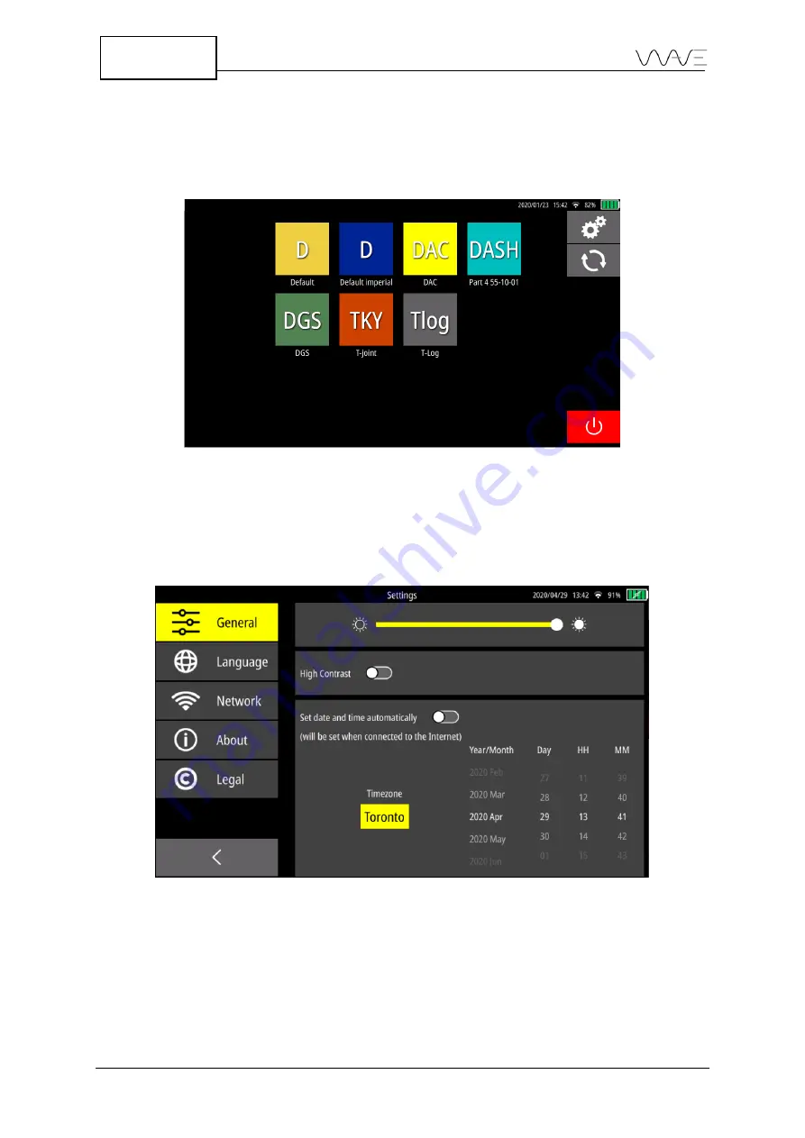
The 

General

 includes three sub-menus, which include the brightness, contrast, and date 

and time.   


Figure 80 

The General sub-menus 

14.1.1


Brightness 

You can change the brightness of the screen by moving your finger on the slider. 


Summary of Contents for Wave

Page 1: ...Wave User Manual ...

Page 2: ...2 Wave User Manual Version 4 ...

Page 3: ...USB C CONNECTOR 15 3 7 1 CHARGING THROUGH USB C 16 3 7 2 USB C TO ETHERNET ADAPTER 16 3 8 THE BATTERY 17 3 8 1 BATTERY ICON 17 3 9 THE UNIT S STAND 17 4 POWERING UP AND SHUTTING DOWN 19 4 1 SHUTTING DOWN THE UNIT 19 5 MAIN SCREEN OVERVIEW 20 5 1 HOME SCREEN 20 5 2 APP DESCRIPTION SCREEN 20 5 2 1 PREFERRED CONFIGURATION 21 5 3 INSPECTION SCREEN 22 5 4 REPORT SCREEN 23 6 THE BASICS INSPECTION SCREEN...

Page 4: ...REMENT IN GATES 42 8 ULTRASONIC PARAMETERS ADVANCED NOTIONS 43 8 1 THE A SCAN VIEW 43 8 1 1 REFERENCE A SCAN 43 8 1 2 A SCAN ZOOM 43 8 1 3 AUTO 80 FSH 44 8 2 TX RX MENU 44 8 3 SIGNAL MENU 45 8 3 1 FILTER REFERENCE TABLE 46 8 4 GATE ADVANCED SETTINGS 47 8 4 1 GATE POLARITY 47 8 4 2 SETTING UP AN ADAPTIVE GATE IN GATE MODE 47 9 THE PROBE SELECTION 48 10 THE PART WIZARD 50 10 1 PART TYPES 50 10 1 1 P...

Page 5: ... DESCRIPTIONS 70 12 7 2 COLOUR PALETTE 71 12 7 3 T MIN FUNCTION 72 12 7 4 CSV FILES 72 13 REPORT 74 13 1 WORKFLOW 74 13 2 SCREENSHOT 75 13 2 1 NAME AND COMMENT 76 13 2 2 RATING AND COLOUR 76 13 2 3 CANCEL AND SAVE 76 13 3 CREATE A REPORT 77 13 3 1 FROM THE INSPECTION SCREEN 77 13 3 2 FROM THE APP DESCRIPTION SCREEN 78 13 4 REPORT CREATING SCREEN 78 13 4 1 SOURCE 78 13 4 2 GENERAL 80 13 4 3 INSPECT...

Page 6: ...NECTION FROM YOUR LAPTOP 98 16 3 SHARING YOUR INTERNET CONNECTION FROM YOUR MOBILE PHONE 99 17 MENUS AND PARAMETERS REFERENCE 100 18 WAVE COMPANION 106 18 1 CONNECT WAVE TO THE WAVE COMPANION 106 18 2 VERSION COMPATIBILITY 106 19 QUALITY ASSURANCE 107 20 MAINTENANCE 108 20 1 TEMPERATURES 108 20 2 SCREEN 108 20 3 CONNECTORS 108 20 4 BATTERY AND POWER SUPPLY 108 20 5 USB C CONNECTOR 109 20 6 TRAVELL...

Page 7: ...Wave User Manual 7 Version 4 23 1 BATTERY 112 23 2 USB C CONNECTOR 112 23 3 SYSTEM STATUS 112 23 4 HARD SHUTDOWN 112 23 5 APPLICATION 113 24 GLOSSARY 114 ...

Page 8: ... implied warranties or conditions of merchantability or fitness for a particular purpose In NO events shall Sonatest Limited its subsidiaries its directors officers employers or agents be liable for indirect special incidental or consequential damages even if Sonatest Limited or its subsidiaries have been advised of the possibility of such damages arising from any defect or error in this manual or...

Page 9: ...g the echoes echo amplitude and gate positions As well Wave allows using all the main sizing methods including DAC and DGS to name a few 1 2 Application Concept Applications are a subset of the Default application that is pre installed on all shipped Wave units The Default app allows access to all functionalities and features and you have the flexibility of setting all parameters to any possible v...

Page 10: ...on 4 2 Wave Carry Case The Wave carry case includes Wave instrument Smart Li on battery pack AC DC battery charger Ethernet to USB C adapter Ethernet cable Quick Start Guide booklet Couplant bottle Figure 1 Wave Transport Case ...

Page 11: ...projective capacitive P CAP technology the touch panel allows multi touch as well as drag and pinch gestures Using working gloves is not a problem as the touchscreen controller has been programmed to adapt to different circumstances Moreover water or couplant will not interfere or affect the behaviour of finger detection 3 2 The Power Button The power button is used to turn the unit on Once the un...

Page 12: ...e power button provides information on Wave s status 3 3 1 The Device Is Turned off If Wave is not connected to the power supply which means it is not charging the LED light is turned off If Wave is connected to the power supply which means the device is charging the LED will blink If Wave is connected to the power supply and it is fully charged a solid green LED light is displayed 3 3 2 The Devic...

Page 13: ...hooked up to the probe Figure 4 Wave connectors and the expansion ports 3 4 1 The UT Connector Pinouts The following tables describe the pinouts of the UT connectors Figure 5 and Figure 6 illustrate the localisation of the pinouts in the Lemo connector and BNC Table 1 TX RX connector pinouts Pin number I O I O type Description 1 In Out Analogue Ultrasound pulse transmitter receiver 2 Out Power Gro...

Page 14: ...cribes the pinouts of the GPIO connector Figure 7 illustrates the localisation of these pinouts Table 3 GPIO connector pinouts Pin number I O I O type Description 1 Out Power 5V DC power supply 500 mA limit 2 Out Power Ground 3 Out TTL 5V Alarm Output 1 General Purpose Output 1 4 Out TTL 5V Alarm Output 2 General Purpose Output 2 5 Out TTL 5V Alarm Output 3 General Purpose Output 3 6 Out TTL 5V Al...

Page 15: ...or Lemo FGG 1K 316 CLAC K Series 1K 16 pin straight plug centre key G 3 6 The Expansion Port The expansion port is a Sonatest proprietary connection that will allow adding extra accessories The protector cap over the expansion port must remain in place to protect the connector It should only be removed when attaching an accessory 3 7 The USB C Connector The USB C connector can be found on the left...

Page 16: ...ery is being recharged IMPORTANT Sonatest recommends a few USB C hubs Please follow these recommendations as some manufacturers may not provide fully USB C compliant devices Go to Sonatest s website to view an updated list of these pre tested hubs 3 7 2 USB C to Ethernet Adapter The unit comes with a small USB C to wired Ethernet adapter This is used to connect your unit to your local network and ...

Page 17: ...oor NOTE Always turn off the instrument before removing the battery Doing differently may cause undesirable effects 3 8 1 Battery Icon The battery icon changes colour depending on the charge level of the device In addition if the device is at10 or less it is recommended to save the configuration turn off the device and replace the battery Figure 10 Battery icon 3 9 The Unit s Stand At the back of ...

Page 18: ...18 Wave User Manual Version 4 ...

Page 19: ...t the bottom just under the display Figure 11 How to power up the Wave 4 1 Shutting Down the Unit Shut down the unit from the Home screen By pressing the red On Off button you will be presented with a confirmation screen where you can select between Shutdown Reboot or Cancel Figure 12 Shutting down from the Home screen Power button ...

Page 20: ...S TKY and Tlog Figure 13 Wave Home screen From this screen you can click on an application to access the App Description screen Settings Software Update You can also close the device with the Power off button 5 2 App Description Screen The App Description screen displays a short description of the app as well as a list of configurations and reports associated with this specific app Moreover for a ...

Page 21: ...con 5 2 1 Preferred Configuration A preferred configuration can be selected This allows the preferred configuration to be located at the top of the list Also this will be the default configuration launched In order to create the preferred configuration long press on the desired configuration A star will appear on the chosen configuration In order to remove the preferred status from a configuration...

Page 22: ... button allows you to take a screenshot name it and add important information see Section 6 4 The menu allows you to navigate through the menus The parameters are dynamically linked to the selected menu Figure 15 Inspection screen Starting from left to right the Inspection screen always displays four measurements The Layout button allows you to change views or groups of views see Section 6 7 Final...

Page 23: ...l tab allows you to add information about the customer and the inspected part The Inspection Summary tab describes the inspection identifies the inspector The Images tab allows you to select the images in the report The UT Parameters tab displays the ultrasound information Finally as the name implies the Probe and Wedge tab displays information related to the probe and wedge used during the inspec...

Page 24: ...are considered as the basic menus Cal Signal TX RX Sizing Part Probe Display Alarms Gate 1 Gate 2 Gate 3 Gate 4 Scan Plan If an app has different menus it means that they have been modified by the Wave Companion To have access to a different menu and its proper list of parameters simply press the displayed menu item to make a list of menus appear Select the desired menu from that list Figure 17 Li...

Page 25: ...screen or not These are described below Table 5 On screen action button Button Action Gain Change gain from 0 dB to 110 dB Reset Zoom Resets A Scan to normal zoom out mode The button is enabled non greyed out when the A Scan is zoomed The A Scan will be zoomed after zooming in on a gate by double tapping on the gate or after zooming in part of the A Scan 6 3 Freeze The table below describes the be...

Page 26: ...surements will also be created In addition you can name your screenshot add comments and use a rating system to identify it All parameters related to the screenshot will be saved for use when a report is created 6 5 Gates Wave supports four 4 gates All can be used simultaneously and all offering all measurements NOTE The gate to gate measurements are possible between Gate 1 and Gate 2 G1 G2 and be...

Page 27: ... length of the gate by clicking on the arrows respectively By clicking on the centre cross you can set the height and the position X axis of the gate While in Scan Plan view mode you can set a gate by directly clicking on the gate of interest Once you click on the gate the Menu will change to the corresponding gate you can then set gate parameters gate enabling gate start gate width gate level and...

Page 28: ... live This value is rounded to the nearest 5 Use the Gate Level parameter if you want to set a gate to any specific level 6 5 3 Setting a Gate on a Scan Plan View When you are set to the Scan Plan view you can still set the gates that are available To set a gate you must go to the Gate menu 1 2 3 or 4 to have access to the desired gate While in the Gate menu you can set the following parameters as...

Page 29: ... like a turned on LED In the above table we can see the status of each of the four 4 alarms Table 9 Alarms Alarm Enabled Status Display Alarm 1 Yes Triggered on Bright Alarm 2 Yes Not triggered off Dimmed Alarm 3 Yes Not triggered off Dimmed Alarm 4 No Invisible NOTE Pressing the alarms at the top bar of the Wave is a direct short cut to the Alarms menu 6 6 1 Alarm On Screen LED Colours Alarms 1 t...

Page 30: ...atically enabled as well By default the source for Alarm 1 is Gate 1 the source for Alarm 2 is Gate 2 and so on 6 6 2 Complex Alarms Wave allows to generate alarms based on complex events For example Alarm 1 could be triggered by conditions from Gate 1 or Gate 2 When an alarm is triggered by a complex condition it will appear differently as shown below Figure 23 Complex alarms In the example above...

Page 31: ...OTE The T Log and A Tlog views are only available when you select T Log in the Sizing menu Similarly the Part view is only available in the Part menu 6 8 Toolbar The toolbar appears at the top right corner It is represented by the common drop down menu icon It includes the following buttons Full Screen Save Report and Exit ...

Page 32: ...A Scan to extend to the full width of the screen Figure 26 Full screen mode 6 8 2 Save a Configuration This is where you can save a configuration that is the complete set up of all parameters It is important to understand that configurations are associated with applications This means a configuration saved when using App A will only be available when using App A It will not be visible when using a...

Page 33: ...port directly from an inspection For more details on how to create reports see Section 13 6 8 4 Quit an Application This button brings you back to the actual App Description screen where the list of configurations and existing reports are shown NOTE When you exit an application the configuration is always automatically saved in the Autosave file Since each application possesses its own list on con...

Page 34: ...Gate 1 is enabled The choice of measurements is then dynamic making it easier to choose from depending on the application running on the instrument and also depending on the number of gates enabled Figure 28 Measurement choices only Gate 1 is enabled Gate to gate measurements are grouped in pairs That is GX GY measurements are offered between Gate 1 and Gate 2 or between Gate 3 and Gate 4 The exam...

Page 35: ...e Depth Surface Distance Gate 1 to Gate 4 Stop Sound Path Depth True Depth Surface Distance Gate 1 to Gate 4 Length The length of the gate G1 G2 G3 G4 Peak Sound Path Depth True Depth Surface Distance G1 G2 G3 G4 Flank Sound Path Depth True Depth Surface Distance Surface Distance Minus X Offset G1 G2 G3 G4 First Peak Sound Path Depth True Depth Surface Distance Surface Distance NOTE The Gate Start...

Page 36: ... following figure shows the aforementioned definitions in graphical form The peak corresponds to B The flank is represented by A The first peak is B Figure 30 Graphical representation of the plank first peak and flank There is also a difference between the depth and true depth Depth is considered as the depth without taking into account multiple half skips Figure 31 Visual representation of depth ...

Page 37: ... 11 Measurement reference Gate Ref Measurement Symbol Meaning GX Peak FSH GX Amplitude of the highest peak in gate Shown even if peak below the gate but peak greater than 5 FSH GX Peak Sound Path GX Sound path distance measured at peak GX Peak Depth GX Depth at peak position GX Peak True Depth GX True depth at peak position takes skips into account GX Peak Surface Distance GX Distance from the exi...

Page 38: ...hown even if the peak is below the gate and if the peak is greater than 5 FSH GX First Peak Sound Path GX 1 Sound path distance measured at the first peak GX First Peak Depth GX 1 Depth at the first peak position GX First Peak True Depth GX 1 True depth at the first peak position takes skips into account GX First Peak Surface Distance GX 1 Distance from the exit point of the probe to the position ...

Page 39: ...el GX Start Sound Path GX start Gate start position relative to sound path GX Start Depth GX start Gate start position relative to depth GX Start True Depth GX start Gate start position relative to true depth GX Start Surface Distance GX start Gate start position relative to the surface distance GX Stop Sound Path GX stop Gate stop position relative to sound path GX Stop Depth GX stop Gate stop po...

Page 40: ...asurement in dB relative to DGS curve Corrected if the gain changed DGS Peak dB DGS U DGS dB U Peak measurement in dB relative to DGS curve Uncorrected if the gain changed Use with care DGS Peak ERS GX ERS Peak Measurement in ERS Equivalent Reflector Size relative to DGS curve Corrected if gain changes G1 G2 Peak Sound Path G1 G2 Difference in sound path distance between gate 1 peak and gate 2 pea...

Page 41: ...h Sometimes a proper measurement cannot be displayed See below regarding the occurrences and reasons for not being able to see a number of one of the measurement areas Table 12 Measurement values Value displayed Meaning N A The value cannot be calculated because at least one of the required conditions to compute it is missing Nothing is being measured below 5 FSH A saturated reading i e over 160 F...

Page 42: ...eference system for positioning both in terms of surface distance and in depth 7 5 Measurements Units To modify the measurement units click on Display menu and click on Units It will switch from SI to Imperial and vice versa 7 6 FSH Measurement in Gates The Full Screen Height FSH in a gate will provide a measurement from 0 up to 160 FSH Above that number the signal is saturated and you will need t...

Page 43: ...izontal Vertical Both Display Ruler Mode Distance Time Display Overlay Mode None Line Band Display Grid Type None Plain Dash Dot Cross Display Grid Alignment Aligned Fixed NOTE The A Scan grid can be aligned with the main tick mark of the horizontal ruler On the other hand the grid can be fixed displaying the traditional 10 vertical lines View the following video for more details about the envelop...

Page 44: ...ily achieved in the following way Position a gate so it covers the peak you want to adjust to 80 Then do a long press of the Gain button This will automatically set the gain level such that the peak covered by the selected gate will be adjusted to 80 FSH The reference level 80 can be set to any FSH percentage by using the Ref Amplitude parameter found in the Cal menu View the following video for m...

Page 45: ... Narrow 1 MHz Wide 1 MHz Narrow 1 25 MHz Wide 1 25 MHz Narrow 2 MHz Wide 2 MHz Narrow 2 25 MHz Wide 2 25 MHz Narrow 3 5 MHz Wide 3 5 MHz Narrow 4 MHz Wide 4 MHz Narrow 4 5 MHz Wide 4 5 MHz Narrow 5 MHz Wide 5 MHz Narrow 7 5 MHz Wide 7 5 MHz Narrow 10 MHz Wide 10 MHz Narrow 15 MHz Wide 15 MHz Narrow 20 MHz Wide 20 MHz Narrow Broadband High Broadband Low Signal Reject Type None Suppressive Linear Si...

Page 46: ...Wide 2 25 1 13 3 38 3 5 MHz Narrow 3 5 2 63 4 38 3 5 MHz Wide 3 5 1 75 5 25 4 MHz Narrow 4 3 5 4 MHz Wide 4 2 6 4 5 MHz Narrow 4 5 3 38 5 63 4 5 MHz Wide 4 5 2 25 6 75 5 MHz Narrow 5 3 75 6 25 5 MHz Wide 5 2 5 7 5 7 5 MHz Narrow 7 5 5 63 9 38 7 5 MHz Wide 7 5 3 75 11 3 10 MHz Narrow 10 7 5 12 5 10 MHz Wide 10 5 15 15 MHz Narrow 15 11 3 18 8 20 MHz Narrow 20 15 25 20 MHz Wide 20 10 30 Broadband Low...

Page 47: ...View the following video for how to use the gates 8 4 2 Setting up an Adaptive Gate in Gate Mode Gate 2 and Gate 4 have an adaptive triggering feature This feature adapts the gate with respect to the start function Gx Start of G1 peak position In the example below G1 Start is set at 12 mm The G1 sound path is 25 4 mm The blanking value is the minimum offset between G1 and G2 Start In this case the...

Page 48: ...sed on some ultrasonic parameters Figure 35 Access to Probe Selection IMPORTANT It is not possible to save a Generic probe file On the other hand you can save these parameters by saving the configuration as it is By pressing the Probe Model menu parameter the Probe Selection screen appears Figure 36 Probe Selection Probe model available by clicking here ...

Page 49: ...obe Model the Angle the Wedge Velocity the Probe Zero the Frequency the Probe Width and the Probe Type Probe Height will always remain greyed and X Offset is only available for angular probes NOTE DGS probes are identified with a small DGS logo next to the manufacturer s name DGS probes are the only probes that can be used to make a DGS sizing method Once a DGS probe is loaded all the menu paramet...

Page 50: ...others will disappear This is one of the special characteristics of this menu 10 1 Part Types There are four 4 part types Flat T joint Corner joint Curved part Figure 37 Part types available on Wave NOTE The part type choice influences the weld types Thus not all weld types will be available depending on the chosen part 10 1 1 Part Type Dimensions Table 17 shows the available dimensions according ...

Page 51: ...oint Thickness X X Horizontal thickness X X Vertical thickness X X Joint height X X Part angle X Curved base X Outside diameter X Inside diameter X NOTE For the Curved type the Inside Diameter is automatically calculated It is therefore impossible for you to modify it It is a read only parameter That is why it is always greyed out 10 2 Weld Types There are twelve 12 weld types including None Squar...

Page 52: ...52 Wave User Manual Version 4 Double V Single U Double U Single J Double J Bevel Groove ...

Page 53: ...chosen beforehand Table 18 illustrates these possibilities A checkbox indicates that the weld is visible for a given part Table 18 Part types vs welds Flat part Curved part T joint Corner joint None X X X X Square Groove X X X X Single V X X Double V X X Single U X Double U X Single J X Double J X Bevel Groove X X X Double Bevel X X Single Fillet Weld X X Double Fillet Welds X ...

Page 54: ...nsions R 𝜶 𝜷 f S1 S2 r1 r2 Top Cap Bottom Cap L1 L2 Lw1 Lw2 None Square Groove X X X Single V X X X X X Double V X X X X X X X X Single U X X X X Double U X X X X X X X X X Single J X X X X X X Double J X X X X X X X X X X Bevel Groove X X X X X Double Bevel X X X X X X X X Single Fillet Weld X X Double Fillet Welds X X X X NOTE For Single U and Double U welds the root opening R is equal to zero S...

Page 55: ...lisation 4 Define the weld if any according to the weld parameters View the following video for how to define a Flat part with a Single V weld View the following video for how to define a T joint with Fillet Welds 10 3 1 Part View The Part View is a view only accessible in the Part menu It allows to focus on the part and its dimensions Thus it is not possible to see a probe or an A Scan These inte...

Page 56: ...set as 20 00 mm for all geometries Ruler Both None Rulers are located on the left and on the bottom axis and can show metric imperial values depending on the unit system Grid Type None Plain Cross By default the dimensions are 10x10mm 1 x1 but can change as you zoom in or out Grid lines may help you on sizing and distance evaluation Weld Visible Yes No This feature allows you to see the weld overl...

Page 57: ...To virtually move the probe over the test piece image you just need to click the probe and move it to the desired position All geometric parameters are then automatically adjusted View the following video for how to move a probe into the Scan Plan View ...

Page 58: ...valuation is by means of the distance amplitude correction DAC DAC curves use a series of reference echoes from a reference block having artificial flaws Due to sound attenuation on materials and beam spread while using angle probes echo heights of same sized reflectors are different at distinct depths sound path 12 2 1 Create a DAC Curve With the help of a calibration block you can set a DAC curv...

Page 59: ...ain To record an echo you should click on Add Point Once the reference gain is set and the first echo is recorded you can randomly record the other points to create a DAC curve You can also delete or replace another point as much as necessary if they consider that the point was not properly taken To delete or replace a point on a DAC curve move the reference window over the point and then click on...

Page 60: ...t sets the trigger of the alarm when DAC curve is on DAC G1 6 dB 0 dB 2 dB 6 dB 10 dB 12 dB and 14 dB Options are directly dependent on DAC sub curves Gain Mode Absolute or relative Split DAC Enabled Turns on off Split DAC option DAC Subcurves 2 6 10 6 14 JIS and Custom 12 2 3 Absolute and Relative DAC Gain Mode Under sizing options the DAC curve height can be displayed in two different ways To dy...

Page 61: ...sed assessment method to use for DAC amplitude measurements Uncorrected U measurements are not compensated with respect to the DAC calibration Figure 43 Gain Mode is set to Absolute and 6 dB of scanning gain has been added 12 2 4 Amplitude Corrected and Uncorrected Measurements You may choose corrected and uncorrected measurements for the amplitude DAC They appear as C and U in the top measurement...

Page 62: ...ws This sizing method is a way to compensate material attenuation and beam characteristics so that reflectors of equal size at distinct depths into a piece will provide the same amplitude response on A Scan 12 3 1 Create a TCG Curve With the help of a calibration block you can set a DAC curve by clicking on the Sizing menu Then click on TCG Before creating a new TCG curve you can set the Reference...

Page 63: ...d you can randomly record the other points to create a TCG curve You can also delete or replace another point as many times as necessary if they consider the point was not properly taken To delete or replace a point on your TCG curve you need to move your reference window over the point and then click on the Delete Selected Point option Figure 46 Creating a TGC curve Here is some additional inform...

Page 64: ... establish an evaluation curve DGS flaw sizing shows the sound response from equivalent reflectors of different sizes at distinct depths by performing mathematical predictions in terms of probe effective diameter frequency and near field length When performing DGS evaluation keep in mind that this defect sizing method shows some limitations and it may lead to no definitive conclusions in some case...

Page 65: ...to your reflector the refracted echo can be located outside of the reference window You can move the reference window forward backward through the A Scan until it encompasses the echo by just clicking on the touch panel You can also enlarge or reduce the window width by directly clicking on the window and then adjusting it according to your needs Press Calibrate once the echo is correctly located ...

Page 66: ...ocity of the reference block View the following video for how to create a DGS curve 12 4 2 DGS Sizing Options Once a DGS curve is created there are the following options available on DGS sizing options menu Table 24 Information regarding the DGS sizing options Option Meaning Transfer Loss The Transfer Loss is the gain to compensate for the difference of attenuation between a reference standard and...

Page 67: ... not need to be aware of echo amplitude Gain level You just need to make sure that the echo corresponds to your reference reflector and maximise its amplitude When the echo is recorded Wave automatically sets the Gain at 80 FSH by default You can change the refence amplitude to other values on Ref Amplitude button based on your requirements Since the reference level is taken dB level it is no long...

Page 68: ...received echo signal and the differential time of flight of the incident ultrasonic wave as it passes through the discontinuity 12 6 1 Perform an API Calibration To perform calibration you must have a calibration block with a reference reflector such as a notch or a side drilled hole Couple your probe with your standard block and try to maximise the echo from the reference reflector Depending on y...

Page 69: ...sate for the difference of attenuation between a reference standard and the part to be inspected 12 7 T log The method to log thickness data the T log also known as Thickness logging enables you to log several thickness measurements in a table These values are colour coded based on different thresholds Min Threshold Max Threshold Tolerance The T log is built using a wizard The first step enables y...

Page 70: ...h respect to data acquisition Table 28 Data acquisition parameters Button Choices Action Store No option available Save the first measurement in the measurement bar from the left hand side Increment Order Right Down Left Down Right Up Left Up Down Right Down Left How to move into the grid T min On or Off This keeps a record of the first minimum value using the left hand side of the measurement bar...

Page 71: ...n have up to six colour palettes The following table features the colours based on the Wave s contrasts The extreme values of each colour are identified Table 29 Colour palette for the T log Normal contrast High contrast Bornes 𝑀𝑖𝑛 𝑡ℎ𝑟𝑒𝑠ℎ𝑜𝑙𝑑 𝑡𝑜𝑙𝑒𝑟𝑒𝑛𝑐𝑒 𝑖𝑛𝑓𝑖𝑛𝑖𝑡𝑒 𝑀𝑖𝑛 𝑡ℎ𝑟𝑒𝑠ℎ𝑜𝑙𝑑 𝑀𝑖𝑛 𝑡ℎ𝑟𝑒𝑠ℎ𝑜𝑙𝑑 𝑡𝑜𝑙𝑒𝑟𝑒𝑛𝑐𝑒 𝑀𝑖𝑛 𝑡ℎ𝑟𝑒𝑠ℎ𝑜𝑙𝑑 𝑀𝑎𝑥 𝑡ℎ𝑟𝑒𝑠ℎ𝑜𝑙𝑑 𝑀𝑎𝑥 𝑡ℎ𝑟𝑒𝑠ℎ𝑜𝑙𝑑 𝑀𝑎𝑥 𝑡ℎ𝑟𝑒𝑠ℎ𝑜𝑙𝑑 𝑡𝑜𝑙𝑒𝑟𝑒𝑛𝑐𝑒 𝑀𝑎𝑥 𝑡ℎ𝑟𝑒𝑠ℎ𝑜𝑙𝑑 𝑡𝑜𝑙𝑒𝑟𝑒𝑛𝑐𝑒 𝑖𝑛𝑓𝑖𝑛𝑖𝑡𝑒 No...

Page 72: ... the Reset T Min This button allows you to reset a new reference value for the minimum thickness starting from the active cell Once activated all measures taken after enabling this function will be taken as a reference for the minimum thickness which represents the new value established This function can be very interesting for you when they perform measurements with significant variations in thic...

Page 73: ...and transfer them to their computers View the figure below for more details Figure 53 Companion interface that shows stored CSV files in the instrument The headers and the measurement relative to each file will be present at the top of the file s data table Values will be shown in the table as a function of measurements taken by you and the table size columns x lines View the details in the figure...

Page 74: ...ally it is possible to send the PDF formatted report by email or to retrieve it through the Wave Companion 13 1 Workflow Creating a report is typically done through a few simple steps These are 1 Save relevant screenshots during inspection flaws or any other noteworthy information 2 Initiate the creation of a report a Select the main screenshot called the Source it is used to namely populate the r...

Page 75: ...a Wi Fi access point 13 2 Screenshot Taking screenshots during the inspection process allows to capture images of A Scans Scan Plans or both as well as the 4 measurements displayed on the screen This is done using the Screen Capture button Figure 57 Using the screenshot button highlighted in red Once the Screen Capture button is hit you are presented with the following screen Figure 58 Entering mo...

Page 76: ...rs as they indicate a flaw The colour is a second characteristic that could be used to categorise screenshots Whether it is to help classify the type of defect differentiate screenshots taken in the morning from those taken in the afternoon or categorise as per the position e g top bottom left side and right side you can choose the category you need Of course neither a rating nor colour need to be...

Page 77: ...ou to switch between A Scan Scan Plan and A Plan i e A Scan and Scan Plan side by side views The Screen Capture button can be pressed at any time from these views 13 3 1 From the Inspection Screen From the Toolbar menu press the Report button Figure 59 Report creation from within the application From there the screenshots related to the current inspection will be displayed first which is an advant...

Page 78: ...m which the UT parameters will be fetched from Later on you can add additional screenshots These will be secondary or additional screenshots This will be done when the Images tab will be selected There are quite a few tools and filters to help when selecting a source screenshot We will explore each of them Again refer to Error Reference source not found 13 4 1 1 Selecting the Source Screenshot To ...

Page 79: ...eenshots having the colour property selected in the filter will appear in the list To select all files whatever their colour property simply select the 5 colour icon in the colour filter drop down list 13 4 1 5 Date Date is not a filter it is a means to put screenshots into order By default screenshots are presented by reverse chronological order You can change this to chronological order by press...

Page 80: ...me sections might be hidden when you glance at the screen Do not hesitate to scroll the screen with your finger By default some fields are empty although a Source is selected In fact these are the few parameters that need to be written manually in the report To do this all you have to do is click on the parameter to be modified A yellow box will appear to indicate the parameter being modified In a...

Page 81: ...n Settings see Section 14 for more information To use the date picker method click on the Calendar icon Figure 65 Scroll down to choose the date 13 4 2 3Part and Weld Dimensions All the parameters of this category are intrinsically linked to the Source For example if the part from the Source is a T joint only the parameters related to the T joint are displayed However it is still possible to modif...

Page 82: ...the limit is reached it will not be possible to add more text Note that line breaks may affect the layout even if the number of characters is not reached If this is the case by clicking on the Preview button a pop up appears on the screen indicating that the text is too long and will be truncated in the PDF report Figure 67 The pop up that warns the description will be truncated 13 4 3 2Inspected ...

Page 83: ... Images The Images tab presents a list of screenshots in a very similar way as the Source tab see above Here multiple selection can be made All selected screenshots will be added to the report Note that the screenshot selected in the Source tab remains the main one meaning that it will be used to determine the UT parameters that will appear in the report Selected images will appear with a large ch...

Page 84: ... side of the screen Therefore you can have the screenshots appear in any order in the report that will be created later 13 4 5 UT Parameters This tab gathers in a single place the parameters directly related to the inspection excluding those with respect to the probe and wedge There are four sections Code Calibration Block Gain and Amplitude and Calibration Figure 70 The sections that are usually ...

Page 85: ...tant repercussions on report quality 13 4 5 3Sizing Mode This section presents the parameters related to the calibration They are dynamically displayed depending on the calibration and the selected source It is not possible to modify them Table 30 shows the parameters according to the calibration selected Table 30 Calibration parameters displayed in the report DAC API AWS DGS TCG Split DAC Transfe...

Page 86: ... manually This means that all other parameters are intrinsically linked to the Source Nevertheless all of them can be modified by a visual keyboard or a numerical keypad Figure 71 Parameters related to the Probe and Wedge tab 13 5 Report Preview At any time you can visualise a preview of the report by pressing the Preview button Figure 72 The Preview button is available at any time in order to vis...

Page 87: ...ction is automatically generated with the information intrinsically linked to the device such as the serial number or the software version 2 If the description is too long it will automatically appear on the second page Second page3 Screenshot s 3 Caption s 4 3 If there are several images selected other pages will be created However the screenshot will never be on the first or last page of the rep...

Page 88: ...hods can also be used You can enter the page number of the page you want to access directly or simply use the navigation arrows as shown inFigure 73Figure 73 Figure 73 There are several ways to navigate through the report 13 6 Save and Name a Report In order to save a report you must press the Preview button in the Report screen Once the report preview is visible click on the Save button Figure 74...

Page 89: ...the Cancel button to go backwards NOTE It is not possible to overwrite an existing report This means that each report must have a unique file name 13 7 View an Existing Report Once a report has been saved it can be viewed again From the App Description screen click on the Report tab The reports saved in the application appear as a list Once the report name is selected simply click on the View butt...

Page 90: ...e Wave Companion allows you to retrieve any files including reports Of course the Wave and the Wave Companion must be on the same network Internet or not For more information on downloading files please refer to the Wave Companion User Manual 13 8 2 By Email IMPORTANT Wave must be connected to the Internet to be able to send an email To access the email function you must view a saved report This c...

Page 91: ...ne valid email address must be entered in the To and Cc fields 13 8 2 2 Subject By default the subject of the email is the report name and its extension It is possible to modify this field by clicking on it A virtual keypad will appear to make the modification 13 8 2 3 Attachment Automatically the selected report is added as an attachment Please note that only one PDF report can be attached It is ...

Page 92: ...ight corner of the Home screen Figure 79 Access to the Settings via the Home screen 14 1 General The General includes three sub menus which include the brightness contrast and date and time Figure 80 The General sub menus 14 1 1 Brightness You can change the brightness of the screen by moving your finger on the slider ...

Page 93: ...ime You can automatically or manually choose the date and time To automatically configure the date and time settings you must be connected to the Internet 14 2 Language You can choose the language of the instrument from the list of available languages The changes are done automatically In short the instrument does not need to be rebooted 14 3 Network The device can be connected to a network either...

Page 94: ...T Properly connect the USB C Ethernet adapter into the Wave USB C connector This reduces the risk of damaging the connector pins No matter how Wave is connected to a network wire or Wi Fi an IP address will be assigned to the device In the case of a wire connection the IP address is visible in the Network section under the Instrument Name Figure 84 The IP address of a Wave unit when it is connecte...

Page 95: ...e 14 3 2 Network Connection via Wi Fi In order to connect Wave to Wi Fi toggle the Wi Fi button Figure 86 Network connection via Wi Fi The available networks are displayed Some icons may appear next to a Wi Fi network A lock indicates it is a private network A password is required A Wi Fi icon indicates the network s signal strength Figure 87 Example of private and public Wi Fi networks Private ne...

Page 96: ... some basic information about your Wave like the date of the Last Calibration the Software Version the Firmware Version and the Serial Number 14 5 Legal Wave was designed to be ultrasonic inspection equipment It has been extensively tested before leaving the manufacturer However operating software may experience untoward issues The instrument must be used only for industrial applications and mater...

Page 97: ...ate is available you will be able to click on the Update button Release notes are available for each update IMPORTANT Wave must be connected to the Internet to be able to update 15 2 USB C Update If the Internet connection is not available it is still possible to update the Wave Simply put the update file on a USB C stick and reach the Software Update screen From there click on the USB tab and the...

Page 98: ...t your Wave by cable or Wi Fi see Section 14 3 for more details Once you are connected to a network an IP address will be automatically set to your instrument Sonatest suggests downloading and installing a VNC viewer on your laptop that allows you to set a remote connection to your instrument This will allow you to share your screen on your laptop s screen For the majority of VNC viewer applicatio...

Page 99: ...e majority of VNC viewers applications you just need to set the IP address from your instrument to get access to it 16 3 Sharing your Internet Connection from your Mobile Phone Your mobile phone should be connected to a mobile network before you start to set up a mobile hotspot To set a mobile hotspot from your mobile phone go to Settings if your mobile is Android based In the Settings home page g...

Page 100: ...wide o 1 25 MHz narrow o 1 25 MHz wide o 2 MHz narrow o 2 MHz wide o 2 25 MHz narrow o 2 25 MHz wide o 3 5 MHz narrow o 3 5 MHz wide o 4 MHz narrow o 4 MHz wide o 4 5 MHz narrow o 4 5 MHz wide o 5 MHz narrow o 5 MHz wide o 7 5 MHz narrow o 7 5 MHz wide o 10 MHz narrow o 10 MHz wide o 15 MHz narrow o 20 MHz narrow o 20 MHz wide o Broadband low o Broadband high Reject Level Reject Type o None o Supp...

Page 101: ...Log Sizing Options Transfer Loss DAC Trigger DAC G1 0 dB Gain Mode Relative Absolute Split DAC Enabled Yes No DAC Sub curves DAC JIS 2 6 10 6 14 Custom Nb of DAC Curves 0 1 2 3 DAC Curve 1 DAC Curve 2 DAC Curve 3 TCG Visible Yes No AWS C Rounded 0 1 1 ABCD Visible Yes No ERS Gain Mode Relative Absolute DGS Trigger DGS G1 DGS Sub curves Ref dB ERS Nb of DGS Curves 0 1 2 3 DGS Curve 1 DGS Curve 2 DG...

Page 102: ...e Part menu is a wizard in fact See Section 9 for more details Probe Model Probe Selection Angle X offset Wedge Velocity Probe Zero Frequency Probe Width Probe Height Probe Type Mono Circular Mono Rectangular Dual Crystal Probe Serial Number ...

Page 103: ...Grid Type None Plain Dash Dot Cross Grid Alignment Fixed Aligned Alarm 1 Enabled Yes No Alarm 1 Source G1 G2 G3 G4 DAC DGS not G1 G1 and G2 G1 or G2 Alarms continued Alarms continued Alarms continued Alarm 2 Enabled Yes No Alarm 2 Source G1 G2 G3 G4 DAC DGS not G2 G1 and G2 G1 or G2 Alarm 3 Enabled Yes No Alarm 3 Source G1 G2 G3 G4 DAC DGS not G3 G3 and G4 G3 or G4 Alarm 4 Enabled Yes No Alarm 4 S...

Page 104: ... Alarm 4 GPO None 0 1 2 3 Gate 1 Gate 2 Gate 3 G1 Enabled Yes No G1 Start G1 Width G1 Level G1 Polarity Absolute Positive Negative G2 Enabled Yes No G2 Start G2 Width G2 Level G2 Polarity Absolute Positive Negative G2 Adaptive Triggering On Off G2 Blanking G3 Enabled Yes No G3 Start G3 Width G3 Level G3 Polarity Absolute Positive Negative ...

Page 105: ...ed Yes No G4 Start G4 Width G4 Level G4 Polarity Absolute Positive Negative G2 Adaptive Triggering On Off G2 Blanking Beam Exit Point Probe Distance Rulers Both None Grid Type None Plain Cross Weld Visible Yes No Signal Visible Yes No Distance Visible Yes No ...

Page 106: ...arding the compatibility between different application versions Wave and Wave Companion Wave Companion can manage several applications that are based on the current version or older versions However these applications should not be corrupted Wave Companion will transfer an application if its version is not as recent as the version of Wave Once exception is version 1 0 X of Wave Companion When an a...

Page 107: ...gned to meet and to surpass several international standards All Wave units are tested for quality assurance before delivery to customers The following list shows the standards that Wave has been tested for EN 12668 EN 61326 1 FCC Part 15 ICES 003 CISPR11 IEC 61000 4 ...

Page 108: ...stic components 20 1 Temperatures Wave s operating temperatures when the fan is working are from 10 C to 45 C 14 F to 113 F 20 2 Screen For the Wave screen we recommend the following advice Do not use an abrasive cloth or brush to clean the screen Do not use a sharp object to point functions on the screens Do not leave or store the unit where the screen will be directly exposed to sunlight for a l...

Page 109: ...el When the battery indicator is down to one quarter full charge the battery as soon as possible NOTE The instrument automatically shuts off when the battery is too weak for reliable operations However current settings are saved and then restored when the instrument is turned on For long work journeys on remote locations or if you are unable to have access to main power supply always carry a spare...

Page 110: ...s Single element probes need to be connected to the proper socket as indicated on the following picture Figure 92 Connectors and the expansion 21 2 Accessories IMPORTANT It is recommended that the instrument should be switched off or at least the pulser stopped for the probe installation If the Wave is not turned off you may cause some damage to the electronic circuits For options availability and...

Page 111: ...nical information and recommendations contained in this manual or any other information supplied by Sonatest Limited in connection with the use features and qualifications of the Wave are based on tests believed to be reliable but the accuracy or completeness thereof is not guaranteed Before using the product you should determine its suitability for your intended use based on your knowledge of ult...

Page 112: ...d charger If you do not have a spare charger try with another battery If the battery life is longer the battery is faulty 23 2 USB C Connector Which USB C adapter should I use Have a look at the Sonatest website sonatest com to see all the adapters compatible with Wave Can I use a USB C adapter which is not in the adapter list Yes However Sonatest does not guarantee the compatibility of the adapte...

Page 113: ...ng Make sure you have not transferred a corrupted application A corrupted application features a logo with a crossed out circle You cannot open this application You must replace the application with one that is not corrupted or simply deleted the corrupted application Figure 93 A corrupted application ...

Page 114: ...k Flank The first positive flank to cross the gate the first value higher than the gate threshold that crosses the gate L1 mm or in Length of the left side fillet weld L2 mm or in Length of the right side fillet weld Lw1 mm or in Effective throat of the left side fillet weld Lw2 mm or in Effective throat of the right side fillet weld Overlay mode Skip overlay mode Peak The highest value inside the...

Page 115: ...ode S1 mm or in Weld depth of the bevel 1 S2 mm or in Weld depth of the bevel 2 TCG Time corrected gain Transfer loss dB dB loss due to surface conditions poor coupling etc X Offset mm or in Distance between the front of the probe and the exit point ...

Page 116: ...116 Wave User Manual Version 4 ...

Page 117: ...United Kingdom t 44 0 1908 316345 e sales sonatest com Distributed by USA Sonatest North America 12775 Cogburn San Antonio Texas 78249 United States t 1 210 697 0335 e sales sonatestinc com Part No 147440 Issue 4_190121 sonatest com Simplicity Capability Reliability ...

Reviews: