66
Wave User Manual
Version 4
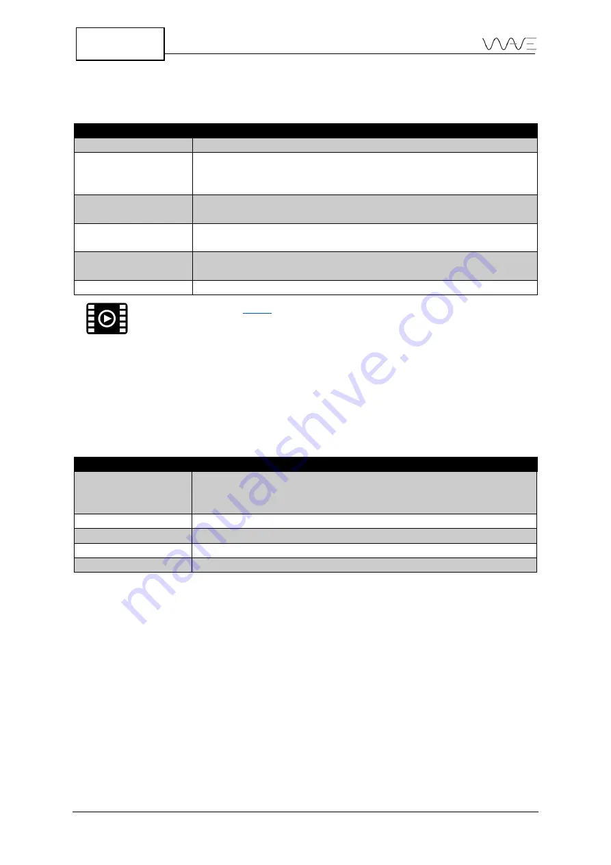
Once a DGS probe is selected, you may set some additional parameters.
Table 23
–
Additional parameters for DGS sizing options
Option
Meaning
Ref. Attenuation
Attenuation finds the attenuation losses at the calibration step.
Material Att.
Material attenuation of the test piece. Once the DGS calibration is
done, it applies the attenuation effect on all DGS curves.
Ref. Type
Reference echo can be a side-drilled hole, flat bottom hole or the
infinite reflector size, also known as the backwall echo.
Ref. Type
Reference echo can be a side-drilled hole, flat bottom hole or the
infinite reflector size, also known as the backwall echo.
Ref. Size
Reference size during the calibration, its type is defined in the
Ref.
Type
tile
Ref. Block Velocity
The velocity of the reference block
for how to create a DGS curve.
12.4.2
DGS Sizing Options
Once a DGS curve is created, there are the following options available on
DGS
sizing
options menu.
Table 24
–
Information regarding the DGS sizing options
Option
Meaning
Transfer Loss
The Transfer Loss is the gain to compensate for the difference of
attenuation between a reference standard and the part to be
inspected.
DGS Trigger
It sets the trigger of the alarm when DGS curve is on (DGS or G1).
Gain Mode
Absolute or relative
ERS
Equivalent Reflector Size
DGS Subcurves
Ref, ERS or dB
12.5
AWS
You can evaluate discontinuities according to AWS D1.1
(American Welding Society)
. This
evaluation is based on signal amplitude comparison. The echo amplitude from a
discontinuity is compared to the echo amplitude of a known reflector. It is defined as an
indication rating according to the code. Sound attenuation in test part is also taken into
account for evaluation.


