12
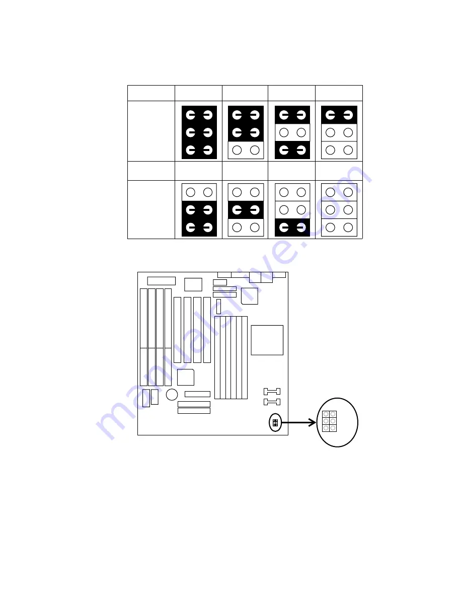
JP1, JP2, JP3: Bus Ratio Select
Set these jumpers according to your CPU clock.
2X
2.5X
3X
3.5X
JP3
JP2
JP1
4X
4.5X
5X
5.5X
Notice that the cap colors of JP1~JP3 are RED.
–
+
JP3JP2JP1
Page 1: ...mputer Inc Companies and products mentioned in this manual are for identification purposes only Product names appearing in this manual may or may not be registered trademarks or copyrights of their re...
Page 2: ...etting 9 System Memory Configuration 9 Cooling FAN Settings 10 Installation 10 Removal 11 Jumper Settings 11 Factory Fixed Jumpers 11 JP1 JP2 JP3 Bus Ratio Select 12 JP18 Clear CMOS Data 13 JP22 CRT T...
Page 3: ...tch 19 JP15 Power On Switch 19 HD1 IDE LED Activity Light 19 IR1 Infrared Port Module Connector 19 USB USB Connector 20 Chapter 3 BIOS Setup 21 Standard CMOS Setup 22 BIOS Features Setup 24 Chipset Fe...
Page 4: ...m hardware based on the Intel Pentium processor and is equipped with four PCI slots four standard ISA slots Super Multi I O controller and dual ports PCI IDE connectors for future expansion The hardwa...
Page 5: ...orts 6pcs SIMM DRAM Socket Supports 4PCI and 4ISA Add In slots Integrated Fast IDE Controller PIO Mode 4 transfers timing PCI IDE Bus Master Support Supports 2 IDE Connectors for the maximum of 4 IDE...
Page 6: ...er On IR CON HDDLED HD1 IR1 JP15 SMI JC5 PCI1 PCI3 PCI2 COM1 P2 PCI4 MS1 KB1 W837877F 82442FX 82371SB 8042 RTC BIOS ISA SLOTS USB1 JP18 Pentium Pro CPU Socket 7 BAT Don t touch the heat sinks avoid bu...
Page 7: ...to upgrade or reconfigure your system and remember to turn off the power of the system as well as all peripheral devices before performing any work on the system Symbols used in this chapter are desc...
Page 8: ...umpers JP9 JP10 and JP1 JP3 according to the CPU type as shown in the following figures CPU 2 5X Clock Setting Pentium Pro CPU Socket 7 JP3 JP2 JP1 JP9 JP10 JP9 JP10 Pentium Pro 150 60 JP9 JP10 Pentiu...
Page 9: ...System Memory Configuration This 82440FX motherboard supports 72 pin SIMMs of 4MB 8MB 16MB or 32MB to form a memory size between 8MB to 384MB Each bank must have 2 pcs of DRAM modules w i same size an...
Page 10: ...ation 1 Place CPU into your socket and put CPU cooler on top of CPU as shown in the following drawing Slide one side hole of clip into the key way of the socket then 1 2 Press another side hole of cli...
Page 11: ...ide hole of the clip and push as shown in the following drawing 1 2 Finished as in the following drawing 2 Jumper Settings Factory Fixed Jumpers The following jumpers are set by the factory Jumpers Fa...
Page 12: ...12 JP1 JP2 JP3 Bus Ratio Select Set these jumpers according to your CPU clock 2X 2 5X 3X 3 5X JP3 JP2 JP1 4X 4 5X 5X 5 5X JP3 JP2 JP1 Notice that the cap colors of JP1 JP3 are RED JP3 JP2 JP1...
Page 13: ...r momentarily then remove the cap to retain new settings COMS Data JP18 Clear Data Close Retain Data default Open JP22 CRT Type Select This jumper sets the color or monochrome monitor CRT Type JP22 Mo...
Page 14: ...ese 2 jumpers instructs the clock generator what frequency to send to the CPU Set these jumpers as shown according to the CPU s internal clock speed Settings JP9 JP10 60MHz default 66MHz Notice that t...
Page 15: ...eyboard Connector A 5 pin female DIN keyboard connector is located at the upper right corner of the motherboard Plug the keyboard jack direct to this connector MS1 PS 2 Mouse Connector Attach PS 2 mou...
Page 16: ...16 PRT1 Parallel Port The system board provides a 25 pin parallel port connector COM1 COM2 Serial Port Connectors The system board has two 9 pin serial port connectors COM1 and COM2 COM1 COM2 PRT1...
Page 17: ...connector FDC Connect one end of a floppy drive cable to this connector and the other end to a floppy drive IDE1 IDE2 Primary Secondary IDE Connectors The system board has a 32 bit Enhanced PCI IDE Co...
Page 18: ...e the following drawing for jumper position JC2 Reset Switch The system board has a 2 pin connector for rebooting your computer without having to turn off your power switch This prolongs the life of t...
Page 19: ...E LED Activity Light These connectors connect to the hard disk activity indicator light on the case IR1 Infrared Port Module Connector The system board provides a 5 pin infrared connector IR1 CON as a...
Page 20: ...20 USB USB Connector This jumper connects to the USB cable to provide USB device USB function default is Disabled refer to page 34 for more detail USB 1 GND Vcc D0 Vcc D1 D0 GND D1 GND...
Page 21: ...TO ENTER SETUP 2 Press the DEL key and the main program screen appears as in the following page ROM PCI ISA BIOS CMOS SETUP UTILITY AWARD SOFTWARE INC STANDARD CMOS SETUP BIOS FEATURES SETUP CHIPSET...
Page 22: ...your system hardware configuration or the configuration stored in the CMOS memory got lost or damaged Run the Standard CMOS Setup as follows 1 Choose STANDARD CMOS SETUP from the Main Menu and a scree...
Page 23: ...disk drives installed in your system The choices are 360KB 5 25 in 1 2MB 5 25 in 720KB 3 5 in 1 44M 3 5 in default 2 88MB 3 5 in or None Floppy 3 Mode Support Drive A B Both Enabled 3 5 inch 1 2MB fun...
Page 24: ...Option Setup PCI VGA Palette Snoop Disabled OS 2 Select for DRAMs 64MB Non OS 2 ESC Quit Select Item F1 Help PU PD Modify F5 Old Values Shift F2 Color F6 Load BIOS Defaults F7 Load Setup Defaults Vide...
Page 25: ...routine Boot Sequence Choose C A C CD ROM A CD ROM C A or A C default This option determines which drive to look for first for an operating system Swap Floppy Drive Choose Enabled or Disabled default...
Page 26: ...tem boot up or use of BIOS Setup PCI VGA palette Snoop Choose Enabled or Disabled default It determines whether the MPEG ISA cards can work with PCI VGA or not OS Select for DRAM 64MB Choose Non OS2 d...
Page 27: ...elay Disabled DRAM Read Burst B E F x2 3 4 DRAM Write Burst B E F x3 3 4 ISA Bus Clock PCICLK 4 DRAM Refresh Queue Enabled DRAM RAS Only Refresh Disabled ECC Checking Generation Disabled Fast Dram Ref...
Page 28: ...s are generated by the CPU in four separate parts The 1st part provides the location within the DRAM where the read or write is to take place while the remaining three parts provide the actual data Th...
Page 29: ...when the CPU is running so much faster than the I O bus that the CPU must be delayed to allow for the completion of the I O The choices for 8 bit I O are NA 1 to 8 CPU clock Default is 3 The choices f...
Page 30: ...SC Quit Select Item F1 Help PU PD Modify F5 Old Values Shift F2 Color F6 Load BIOS Defaults F7 Load Setup Defaults Power Down Resume Events IRQ 3 COM 2 ON IRQ 4 COM 1 ON IRQ 5 LPT 2 ON IRQ 6 Floppy Di...
Page 31: ...speed down to 33MHz during this mode Standby Mode Suspend Mode These two options allow you to choose the mode for the different timers The Standby Mode turns off the VGA monitor and the Suspend Mode...
Page 32: ...4 assigned to PCI ISA PnP IRQ 15 assigned to PCI ISA PnP DMA 0 assigned to PCI ISA PnP DMA 1 assigned to PCI ISA PnP DMA 3 assigned to PCI ISA PnP DMA 5 assigned to PCI ISA PnP DMA 6 assigned to PCI I...
Page 33: ...tion data in BIOS IRQ x assigned to DMA x assigned to Legacy ISA Manually assigns IRQ DMA to device PCI ISA PnP BIOS assigns IRQ DMA to device automatically PCI IRQ Actived By Choose Edge or Level def...
Page 34: ...GRATED PERIPHERALS AWARD SOFTWARE INC ESC Quit Select Item F1 Help PU PD Modify F5 Old Values Shift F2 Color F6 Load BIOS Defaults F7 Load Setup Defaults USB Controller Disabled IDE HDD Block Mode Ena...
Page 35: ...oose Auto default or Mode 0 4 The BIOS will detect the HDD Mode type automatically when you choose Auto You need to set to a lower mode than Auto when your hard disk becomes unstable On Chip Primary S...
Page 36: ...t transmit and receive activities at the same time Full Transmit and receive activities at the same time RxD TxD Active Choose Hi Hi Hi Lo Lo Hi or Lo Lo default The above 2 options won t work unless...
Page 37: ...he above 2 options won t work unless EPP ECP function is selected USB Controller Enabled Enable USB function and it will occupy one IRQ usually the IRQ11 Disabled default Disable USB function and it w...
Page 38: ...ppears prompting you to confirm the password Confirm Password 4 Enter exact the same password you just typed again to confirm the password and press Enter 5 Move the cursor to Save Exit Setup to save...
Page 39: ...you may press the ESC after the Enter to skip this function and go back to the Main Menu Save Exit Setup Save Exit Setup allows you to save all modifications you have specified into the CMOS memory H...