background image

CIE-M10A User Manual Ver. 1.0


- 28 - 

https://www.ezTCP.com


 5


Methods for I/O control 

5.1


Modbus/TCP 

CIE-M10A  supports  Modbus/TCP.  By  using  this  protocol,  it  remotely  monitors  and 

controls I/O devices. To use this method, user

s’

 application should support this protocol. 

5.1.1  .Related Parameters 

parameter 

description 

Modbus/TCP 

Using Modbus/TCP for controlling I/O ports of CIE-M10A. 

Slave 

The slave responses by queries from the Master 

Master 

The Master sends queries to the slaves 

Poll Interval 

the period for sending queries (Unit: ms, Minimum value: 10) 

Unit ID 

ID for identifying the device or the pair of devices. 

Input Port Base 

Address 

Initial address of the input ports 

Output Port Base 

Address 

Initial address of the output ports 

Passive Connection  waiting for accepting a Modbus/TCP connection 

Active Connection 

requesting a Modbus/TCP connection 

Multiple Connection  The numbers for multiple Modbus/TCP connections. 

Control Method of 

(FC XX) 

Control method for the output ports of the slave (Single / 
Multiple) 

Control Method of 

(AND/OR) 

Control method for the output ports of the master (AND / OR) 

Peer Address 

Peer

s IP address when CIE-M10A performs active connections 

Peer Port (Active) 

Peer

s port when CIE-M10A performs active connections. 

Local port (Passive) 

CIE-M10A

s local port when CIE-M10A performs passive 

connections. 

Input Change 

Notification 

A function for immediate notification of changing the IP address. 

Initialize the output 

port state 

The Output port will be changed to the [Initial State] when 
Modbus/TCP is disconnected. (Upper version 1.5A) 

Macro 

Applying macro function on the output port 

Initial State 

Output port value when CIE-M10A boots up.   

Table 5-1 Modbus/TCP related parameters 


We do not recommend changing the [Input Port Base Address] and [Output Port Base 
Address] unless you need to.


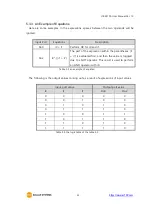
Summary of Contents for CIE-M10A

Page 1: ...Sollae Systems Co Ltd https www ezTCP com 8ports Remote I O Controller CIE M10A User Manual Version 1 0 8ports Remote I O Controller CIE M10A User Manual Version 1 0...

Page 2: ...ensuring this product is disposed of correctly you will help prevent potential negative consequences to the environment and human health which could otherwise be caused by inappropriate disposal of th...

Page 3: ...gital Output Ports 13 1 5 6 Ethernet Interface 14 1 5 7 RS232 Port DB9M 14 1 5 8 System LED 15 2 Installation and Test 16 2 1 Installation 16 2 1 1 Setting Network Aera 16 2 2 Test operation 18 2 2 1...

Page 4: ...3 Modbus TCP Master Mode 29 5 1 4 TCP Connection Modes 30 5 1 5 Initial State 30 5 1 6 Write Pulse 30 5 2 Serialized Modbus TCP 30 5 3 Macro Mode 31 5 3 1 Operator 31 5 3 2 Operand 31 5 3 3 An Example...

Page 5: ...IP Change 56 8 2 2 Sending MAC Address 57 8 2 3 Debugging Message 57 8 3 Serial Port Tab Functions 59 8 3 1 TELNET COM port Control Option RFC 2217 59 8 3 2 Disable TCP Transmission Delay 59 8 3 3 Dat...

Page 6: ...1Technical Support 66 11 2Warranty 66 11 2 1 Refund 66 11 2 2 Free Repair Services 66 11 2 3 Charged Repair Services 66 12 Precaution and Exemption from Liability 67 12 1Precaution 67 12 2Exemption f...

Page 7: ...or these functions CIE M10A can be used in another way because it equipped operation as a serial device server 1 2 Features Remote I O controller Module type with a built in RJ45 connector for Etherne...

Page 8: ...ual Ver 1 0 7 https www ezTCP com 1 3 Application Examples Remote I O device server Figure 1 1 remote I O device server Serialized Modbus TCP Figure 1 2 serialized Modbus TCP Internet Switch Figure 1...

Page 9: ...CIE M10A User Manual Ver 1 0 8 https www ezTCP com Macro mode Figure 1 4 macro mode Serial Switch Figure 1 5 serial switch Serial Device Server Figure 1 6 serial device server...

Page 10: ...o MDI MDIX Cable Auto sensing Temperature Operate 40 85 Storage 40 85 Environment Follows Europe RoHS Directive Table 1 1 H W specification 1 4 2 S W specification Protocol TCP UDP IP ICMP ARP DHCP DN...

Page 11: ...ce 1 5 1 Dimension Top view Figure 1 7 top view Front and Side view Figure 1 8 front and side view According to conditions of soldering components the real dimensions might be differed with the above...

Page 12: ...2 9V Max VOL 0 4V 17 GND Ground 18 GND Ground 19 ADVREF ADC VCC Reference Input Voltage Range 2 6V 3 3V In 20 ADC_IN0 Analog Input Port 0 Input Voltage Range 0V ADVREF In 10 bit ADC Conversion Time 2...

Page 13: ...owing is a circuit example with a photo coupler which isolates circuits electrically Figure 1 9 a circuit of the input port The INPUT 1 and INPUT 2 ports are user interface port The working voltage is...

Page 14: ...ltage of the ADC_IN0 0V ADVREF to 0 1023 digital value User can read this value through Modbus TCP and HTTP User can read the ADC value from the address of Digital Input Port Address 4 via Modbus TCP...

Page 15: ...with the hardware address set in the factory Figure 1 12 the RJ45 connector 1 5 7 RS232 Port DB9M There is a UART port which is 3 3V level This port provides serial to TCP IP converting function work...

Page 16: ...inking every second Assigned an IP address Blinking 4 times at once Without being assigned an IP address by DHCP ON Establishing a Modbus TCP connection Blinking Transferring data to the Ethernet LINK...

Page 17: ...through network hubs Figure 2 1 the connection between CIE M10A and a PC Because CIE M10A is a type of module you might need designing a board for it If you cannot design the board please consider usi...

Page 18: ...parameters are listed on the table below To make the test simple keep these values during the test parameter value Network Local IP Address 10 1 0 1 Subnet Mask 255 0 0 0 Option Telnet Checked IP Add...

Page 19: ...u can see the window as shown below Figure 2 3 Modbus TCP test program of the ezManager Search the connected CIE M10A with Search All button Select a MAC address of searched product on the search resu...

Page 20: ...nput the local port for Modbus TCP of CIE M10A In a local area network and steps can be omitted Connect by pressing Connect button Under the connection check if the Di LEDs are turned on or off with s...

Page 21: ...test Input the IP address of your CIE M10A on the address field Ex 10 1 0 1 Check if the DI LEDs are turned on or off with HIGH signal Check if DO LEDs are turned on or off with clicking the each of...

Page 22: ...ial appearance of ezManager 3 1 1 Configuration via LAN Checklists Make sure of the connection between your PC and CIE M10A via Ethernet If they are in the same network MAC Address search button can b...

Page 23: ...rial configuration mode by connecting ISP pin with GND LOW less than 1 second After then read the setting on the Serial tab Procedures Figure 3 3 procedures for configuration via serial port Step 2 Re...

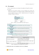
Page 24: ...ode you can change some parameters through the serial port Figure 3 5 setting the communication mode to the AT command Procedures Figure 3 6 procedures for configuration with AT command Division Avail...

Page 25: ...also available in this mode Serial configuration mode This mode is for configuring environmental parameters through the RS 232 port ISP mode This mode is for upgrading firmware and HTML files In addit...

Page 26: ...trol I O and an additional operation which operates as a Serial to Ethernet converter I O controller type description Modbus TCP Control and monitor the I O of CIE M10A via Modbus TCP It supports both...

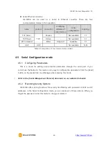
Page 27: ...munication modes 4 5 Serial Configuration mode 4 5 1 Configuring Parameters This is a mode for setting environmental parameters through the serial port If you cannot use the Network this mode is only...

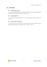
Page 28: ...ger For more details about this please refer to the section 7 1 4 6 2 Upgrading HTML ISP mode can also upgrade HTML files For more details about this please refer to the section 7 2 4 6 3 Revoking Ser...

Page 29: ...Connection requesting a Modbus TCP connection Multiple Connection The numbers for multiple Modbus TCP connections Control Method of FC XX Control method for the output ports of the slave Single Multi...

Page 30: ...Port Base Address 5 1 3 Modbus TCP Master Mode In this mode CIE M10A operates as a Modbus TCP master As a master CIE M10A transmits its input information to the salve and outputs the slave s input val...

Page 31: ...ssive active connection 5 1 5 Initial State The initial state of CIE M10A s output ports can be configured The output ports are set to ON or OFF according to the value of Initial State at the boot tim...

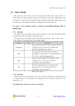
Page 32: ...parenthesis NOT AND OR Each operator is represented by the following symbols name sign description Parenthesis Since calculations within the parenthesis have the highest priority they will be calculat...

Page 33: ...he expression within the parentheses i1 i7 is evaluated first and then the value is toggled due to a NOT operator This result is used to perform an AND operator with i0 Table 5 5 an example of equatio...

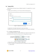
Page 34: ...quired Leave blank or put a random name Password should be the same with a password which is set through the ezManager 5 4 1 Changing the Web HTTP port In case you cannot use the port number 80 defaul...

Page 35: ...ou get some simple syntax it is possible to monitor and control the I O ports with your homepage interface Upgrading Boot and Firmware CIE M10A has a default web page HTML file Except for the page we...

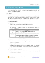
Page 36: ...etting event bytes users can handle the serial data received before a TCP connection is established Value Description 0 CIE M10A does not send the data received before a TCP connection is established...

Page 37: ...TCP server time chart in the case Event Byte is set to 0 Time States CIE M10A is waiting for request segments of a TCP connection Remote host has sent a request SYN segment Processes of the connection...

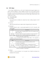
Page 38: ...st segments for the TCP connection with this parameter Value Description 0 CIE M10A sends a request segment of the TCP connection right after it boots up Otherwise 512 or under CIE M10A sends the segm...

Page 39: ...s is required when users use a host name instead of the IP address on the Peer Port parameter 6 2 2 An Example An example of TCP client Figure 6 2 time chart in the case Event Byte is set to 0 Time St...

Page 40: ...CIE M10A is waiting for request segments of a TCP connection The connection has been established CIE M10A is on line and processes of the disconnection The connection has been terminated Both sides a...

Page 41: ...plp Local Port at plp 1470 CR prip Peer IP Address at prip 10 1 0 2 CR prp Peer Port at prp 1470 CR pdc DHCP at pdc 1 CR On pto Timeout at pto 10 CR pwp Store setting at pwp CR Table 6 7 some of exte...

Page 42: ...0A waits request segments of a TCP connection with the ATA command CIE M10A is waiting for requests of a TCP connection A remote host has sent SYN segment to CIE M10A Processes of the TCP connection T...

Page 43: ...States Set parameters in the AT command mode CIE M10A sends a request segment of a TCP connection with the ATD command Processes of the TCP connection The TCP connection has been established CIE M10A...

Page 44: ...e is up to 1460 bytes Data Frame Interval Data Frame Interval means the time for gathering data to make them into a block Its unit is 10ms If there is no transmission for specific time which is set to...

Page 45: ...me interval is 1s Time States CIE M10A is receiving data from the serial port CIE M10A Sends 5 bytes as one block based on the Block Size Serial device sends data 678 to CIE M10A Data 678 has arrived...

Page 46: ...6 11 setting for dynamic update of peer host function Figure 6 7 time chart for dynamic update of peer host Time States Sending any UDP data to the network is impossible UDP data arrives from Remote H...

Page 47: ...ware file We update our homepage when a new firmware is released You can find it on our website Entering ISP mode Enter ISP mode to download firmware file to CIE M10A Run a TFTP client and ready to se...

Page 48: ...nual Ver 1 0 47 https www ezTCP com Checking firmware file and Sending Figure 7 2 sending firmware file Check if the name and path of the firmware file are correct Click the Send button Confirm the co...

Page 49: ...HTTP 7 2 2 Processes Making Users webpage or Downloading sample files Make your own webpage file or use sample webpage files freely available to download at our web site Entering ISP mode Enter ISP mo...

Page 50: ...h the client program Click the Change F W HTML button Figure 7 4 running TFTP client Click the Advanced Menu Change F W HTML button to run TFTP client Select the Change HTML radio button Input the IP...

Page 51: ...e the TELNET option is activated users can remotely log in to CIE M10A If a password is set users should input the password After that messages from CIE M10A appear as shown in the figure below Defaul...

Page 52: ...lsh sc com1 close sd OP1 OP2 Capturing Serial Data lsh sd 1 100 Serial Data Capturing Stops lsh sd 1 0 exit Telnet Session Exit lsh exit Table 7 1 commands for checking states st net st net command d...

Page 53: ...case letters are only allowed to use sc command sd sd command is for capturing serial data OP1 means name of the session OP2 means period which has a 10ms unit for the capture Figure 7 11 sd command...

Page 54: ...tatus is automatically updated in every second Figure 7 14 status window of ezManager FIRMWARE VERSION The name of model and the version of firmware are displayed here SYSTEM UPTIME Operating time of...

Page 55: ...3 SERIAL STATUS I O PORT STATUS This represents I O ports status 1 means HIGH ON and 0 means LOW OFF ARP TABLE This part shows ARP table on CIE M10A When a TCP connection is established or UDP data co...

Page 56: ...amples IP Address Network Mask Allowed IP Address Range 10 1 0 1 255 0 0 0 10 1 0 1 10 255 255 254 10 1 0 1 255 255 255 0 10 1 0 1 10 1 0 254 192 168 1 4 255 255 255 255 192 168 1 4 Table 8 1 examples...

Page 57: ...create host names on the website of DynDNS before use this All about service usage of an account could be changed according to the policy of DynDNS Homepage of DynDNS https dyn com dns Figure 8 1 set...

Page 58: ...on Figure 8 2 setting of Sending MAC Address function Move to the Option tab Check the Send MAC Address option 8 2 3 Debugging Message By using Debugging option users can receive debugging messages fr...

Page 59: ...apturing debugging messages from CIE M10A To stop capturing debugging messages from CIE M10A Unavailable Load Message is for loading a debugging log file to display Closing debugging message window Wh...

Page 60: ...are changed 8 3 2 Disable TCP Transmission Delay If you use this option CIE M10A sends the data from the serial port to Ethernet as quickly as possible 8 3 3 Data Frame Interval Before sending data fr...

Page 61: ...s mode you do not need to change the mode for switching active or passive TCP connection Note that the Event Byte option should be set to 1 or lager value 8 3 6 Separator Using this function you can c...

Page 62: ...id Time If the signals are not maintained for the Valid Time the input signals will be ignored The unit used for the Valid Time is 1ms However because the accuracy is only guaranteed in 10ms the desig...

Page 63: ...ograms have firewall functions so it can cause some trouble to search CIE M10A Close or pause these programs before searching the product Stable supply of the power Check if the power is supplied cont...

Page 64: ...need strong security the access may be denied by their firewall Under this circumstance users should ask the person in charge of their network to release ports which will be used Ex TCP 502 UDP 50005...

Page 65: ...lated parameters that Unit ID Input Port Base Address Output Port Base Address Poll Interval and Notify Input change Checking which mode is using In case of MACRO or serialized Modbus TCP you can cont...

Page 66: ...our website Datasheet Modbus TCP protocol Internet switch Combinations of I O Controllers Digital Pulse Output IP Change Notification DDNS Sending MAC Address function TCP Server Client mode Telnet CO...

Page 67: ...the customer s request to refund the product within two weeks after purchase Sollae Systems will refund the product 11 2 2 Free Repair Services For product failures occurring within two years after pu...

Page 68: ...d applications provided by Sollae Systems for purposes other than those for which they were designed is prohibited Do not use the product in an extremely cold or hot place or in a place where vibratio...

Page 69: ...lt in financial losses damage to property personal injury or the death of people or animals If you use the CIE M10A voluntarily or involuntarily for such unauthorized applications you agree to subtrac...

Page 70: ...ni en milieu explosif ni dans des enceintes nucl aires ni dans des ascenseurs ni dans des a roports ni dans des enceintes hospitaliers ni pour des applications caract re m dical ni dans des dispositi...

Page 71: ...le de la poubelle barr pr sent sur le CIE M10A indique que vous ne pouvez pas vous d barrasser de ce dernier de la m me fa on que vos d chets courants Au contraire vous tes responsable de l vacuation...

Page 72: ...CIE M10A User Manual Ver 1 0 71 https www ezTCP com 13 Revision History Date Version Comment Author 2020 05 22 1 0 Initial Release Sara...

Reviews: