background image

SECTION 6


 WEB REMOTE INTERFACE

All  the  features  and  configurations  of  the  UX24

can be controlled remotely by connecting the con-

sole   to   the   LAN,   and   accessing   the   IP   address

with a WEB browser.

NOTE

Remember that you can expand to 18 or 24 the number

of hardware faders, to have all channels on the surface

UX24.

6.1 Connecting to LAN

 Step 1 

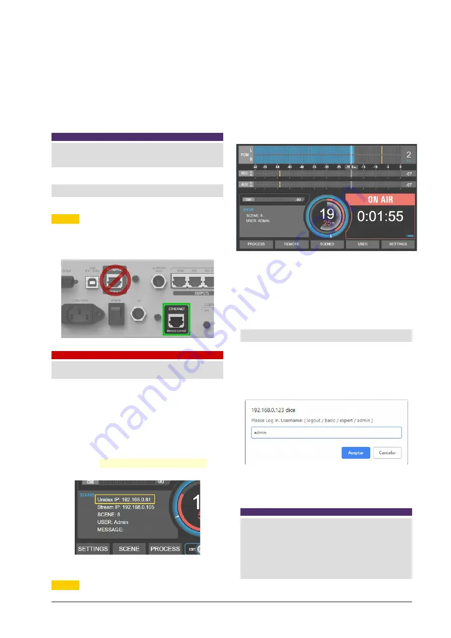
Connect the Ethernet port REMOTE CONTROL to

the LAN, using the factory-supplied Ethernet ca-

ble.

WARNING

UX24 has two Ethernet ports: REMOTE CONTROL and

STREAMING. Pay attention to avoid confusing port.

By default, the console comes with a 

dynamic IP

address (DHCP enabled). The router of local net-

work will assign a free IP address. The assigned

IP address is dynamic, which can change if the

UX24 is restarted. A static IP address can be as-

signed   from   the   system   settings   screen   (SET-

TINGS   SYSTEM).

The assigned IP is shown on the main screen.

 Step 2 

From   a   computer   connected   to   the   same   LAN

(with cable or WiFi) open a web browser (we rec-

ommend   Google   Chrome)   and   enter   the   IP   ad-

dress of the console.
The main screen will open, showing the level indi-

cators and a main menu.

WEB   screens   contain   the   same   options   as   the

screen integrated in the UX24, although the layout

and   shape   of   the   controls   may   differ.   Only   the

screens with the greatest differences are detailed

below.

6.2 USER

Allows you to enter a user profile for the web in-

terface,   regardless   of   the   user   logged   into   the

UX24 hardware. A dialog box will be displayed to

enter the username, and then another to enter the

password.

By default, the password is the same as the user's

name.  The   Logout   option   leaves   the   console   in

the BASIC profile.

NOTE

Remember that three user profiles are available: 

     ADMIN

, with full access;  

   EXPERT

  with partial access to some advances ea-

tures; 

    BASIC

, whit restricted access. 

By default UX24 starts loading the user profile ADMIN. 

www.SolidynePro.com

Solidyne UNIDEX UX24

Page 41

Summary of Contents for UNIDEX UX24

Page 1: ......

Page 2: ...Page 2 Solidyne UNIDEX UX24 www SolidynePro com...

Page 3: ...g 11 2 4 1 General recommendations 11 2 4 2 RJ45 nomenclature 11 2 4 3 RJ45 inputs and outputs 12 2 4 4 Solidyne UX24 wiring kits 12 2 4 4 1 To RCA unbalanced 12 2 4 4 2 To balanced XLR 12 2 4 4 3 To...

Page 4: ...IR ON STARTING 24 2 NETWORK SETTINGS Ethernet control 24 3 CLOCK SETTINGS 24 4 7 Streaming 25 4 7 1 Streaming signal and send level 25 4 7 2 Connection and settings 25 4 7 3 UP STREAM TX 25 4 7 3 1 IC...

Page 5: ...AMS AND ANNEXES 45 Quick installation guides 45 Diagrams 45 SECTION 8 TECH SPECS 47 Main Features 47 Inputs 32 47 Outputs 28 47 GPIO Intercom and auxiliary devices 47 Audio specifications 47 Digital i...

Page 6: ...Page 6 Solidyne UNIDEX UX24 www SolidynePro com...

Page 7: ...e another 12 virtual faders from a touch screen on board Everything can also be managed from an external tablet or computer As an option up to two panels hardware of 6 faders can be added to obtain a...

Page 8: ...stereo sends assignable It are recognized in Windows as Solidyne USB recording devices 4 AES 3 two assignables Dual streaming PCM MP3 RTP Icecast Shoucast upstream 1 2 4 Monitoring and intercoms 2 ou...

Page 9: ...tates installation anywhere in the world due to the availability of components and assembly tools used in data net works At the end of the multipair cable the con nection to an audio equipment microph...

Page 10: ...a USB AES3 UNIDEX inputs can also be used as conventional line level audio inputs balanced Each RJ45 UNIDEX connector corresponds to one input and contains two channels left and right if stereo In thi...

Page 11: ...AES 4 signals can be assigned by the user 2 3 10 Streaming H Ethernet port for streaming UX24 can gen erate two differentiated audio streams and can decode one incoming streaming A streaming uses the...

Page 12: ...link http www solidynepro com consola de audio de bc accesorios y cables Next figures details the connections between RJ45 and common audio connectors 2 4 4 1 To RCA unbalanced 2 4 4 2 To balanced XL...

Page 13: ...D5 monitoring boxes optional manages up to five headphones HD5 and monitor speakers among other features see 2 13 Studiobox HD3 and HD5 Connects with a shielded multipair STP RJ45 to RJ45 flat pin to...

Page 14: ...ort circuit 2 9 GPIO The GPIO General Purpose Input Output connec tor offers 4 inputs and 8 outputs The GPIs allows to command some UX24 features like mics activa tion GPOs can trigger external device...

Page 15: ...tor UDX 2TEL y 2TEL P 2 lines hybrid POTS UDX TEL BT Combined Hybrid with one POTS and one bluetooth link for smart phone UDX USB USB to AES 3 Stereo I O to con nect computers to the console 3 2 UDX 2...

Page 16: ...operated from the console surface The operator can dial answer a call leave it on hold dialogue privately and put the call on the air Each line is handled on individual channels 3 3 1 Connecting UDX 2...

Page 17: ...hange The UDX TEL adapters have internal RF rejection filters both in the medium wave band AM and in the VHF and UHF bands and it is not usually nec essary to add any type of additional filter Tele ph...

Page 18: ...values so a fine calibration is necessary If the rejection value is not the optimal when a call is on the air the voice of the Studio announcer can be affected colored by the audio of the telephone co...

Page 19: ...nnector minijack This is a line level output intended for use with powered speakers The aux input is used to connect an alternative sig nal to the main assigned from the console ON AIR PGM AUD SEND or...

Page 20: ...functions 1 When the microphones are turned off press ing the Studiobox Intercom who is in the Stu dio can speak to the Control Room Stu diobox has a contact microphone for this purpose At the Control...

Page 21: ...ion for default empty scenes CH NAME MODE INPUT M ST 1 MIC 1 MIC MIC 1 M 2 MIC 2 MIC MIC 2 M 3 MIC 3 MIC MIC 3 M 4 MIC 4 MIC MIC 4 M 5 MIC 5 UDX5 MIC UNIDEX5 L M 6 MIC 6 UDX5 MIC UNIDEX5 R M 7 PH LINE...

Page 22: ...When an input is set as mono left and right channels ungroups and can be selected as independent channels 3 GAIN Changes the input gain Each time that an input is selected on the list the focus is on...

Page 23: ...STUDIO B SPEAKERS This option enables the output for connection of monitor speakers in Studio B When the micro phones assigned to Studio B are activated this out put will be muted 6 SOURCE Sets the s...

Page 24: ...input must also be re es tablished by itself Default BUS Buses that will be turned on at the channel associated with the default input Start Level Channel s fader level In physical chan nels this leve...

Page 25: ...sing the Stream IP address 4 7 3 UP STREAM TX This option is accessed from the console by press ing SETTINGS on the main screen SETTINGS STREAMING has four tabs to configure the different features The...

Page 26: ...D CHANNEL ON OFF TALLY A TALLY B TELCO RING Examples The following settings GPI 1 CHANNEL ON OFF CHANNEL 1 will cause that Channel 1 turn on off according to the signal present at the input GPI 1 The...

Page 27: ...functions are controlled audio processors virtual channels channels not assigned to real faders simplified functions for telecom munications scenes This screen also con tains the level meters clock a...

Page 28: ...user profile has access This menu option is not enabled when working at the BASIC or EXPERT level It contains all the advanced and system con figuration options including the assign ment of inputs an...

Page 29: ...icrophone is activated to talk to the telephone line 3 ON AIR button It s the ON OFF button When is ON the signal sends on air to the mix buses The level is set with the main fader 4 DISPLAY OLED scre...

Page 30: ...s a rotary knob that controls the level of the CUE bus The main screen shows a CUE level meter in dBfs This indicator shows the level after the CUE level control therefore there is no indi cation if t...

Page 31: ...the option PROCESS at the main screen 3 Pressing the option SELECT on the CHANNEL screen or a PROCESS screen EQ compresor etc When the SELECT mode is active the CUE buttons light blue and the channel...

Page 32: ...rtual channels are 100 operational from the touch screen for convenient operation it is recom mended to use the remote web interface which can run on a larger screen or tablet The level at the outputs...

Page 33: ...n If all channels work in CUE SOLO mode there will always be only one CUE turned on A usual configu ration is to work the lines as CUE SOLO mode computers and audio players and the micro phones and TE...

Page 34: ...old When a call is on air it allows to end the communication 8 CONFIG Reports the type of adapter associ ated with the channel and configuration options The content of this sector varies according to...

Page 35: ...THE CALL LEVEL CALLING ON AIR VOLUME Do not mix calls with exces sive level The UDX TEL adapter has a high but not abso lute rejection The audio sent to the line the voice of the announcers is not can...

Page 36: ...pro cessor is done with the encoder and tactile options In the explanations that follow it is detailed for each case which parameters handles the encoder and which are tactile 5 9 1 PARAMETRIC ECUALIZ...

Page 37: ...T GAIN ATTACK HOLD RELEASE The functions ATTENUATION STYLE BY PASS are change using the touch screen 1 Transfer curve Graphical representation of the dynamic processor input output curve includ ing th...

Page 38: ...uch screen 1 Type Presets Changes the behavior of de esser 2 Frequency start Lower frequency for the working range Usual values are between 4 500 to 5 500 Hz according to the characteristics of the vo...

Page 39: ...tup the password is never requested You can change the boot user from the screen SETTINGS USERS and change pass words for ADMIN and EXPERT 2 SCENES It shows the list of 12 scenes that can be loaded di...

Page 40: ...ne the position of one or more channels 1 Touch the ORDER CH option A drop down menu appears beside the names that allows re assign the position of each channel 2 At the channel that wants to change d...

Page 41: ...P is shown on the main screen Step 2 From a computer connected to the same LAN with cable or WiFi open a web browser we rec ommend Google Chrome and enter the IP ad dress of the console The main scree...

Page 42: ...face are reflected in the console BUSES Assign the chanel to a bus The virtual bus VBUS do not have a hardware button It is switched from the on board touch screen screen CHAN NEL or from remote Inter...

Page 43: ...CHANNEL from the CHANNEL menu and the processors of the input assigned to that chan nel will be displayed 2 In the case of parametric EQ the ON OFF buttons allow each band to be enabled or not while b...

Page 44: ...EMPTY PAGE Page 44 Solidyne UNIDEX UX24 www SolidynePro com...

Page 45: ...om descargas productos ENG UDXTEL BT_Quick_Installation_Guide pdf Diagrams Inputs and outputs map without Dante option http solidynepro com descargas productos UX24_Quickguide_Inputs_and_Outputs_featu...

Page 46: ...EMPTY PAGE Page 46 Solidyne UNIDEX UX24 www SolidynePro com...

Page 47: ...ol Room speakers and headphones 2 monitoring for Studio speakers and headphones talkback GPIO Intercom and auxiliary devices 2 ON AIR tally light Studios A B 12 VCC 250ma 4 GPI general purpose inputs...

Page 48: ...antom power 48v Analog outputs Flexible routing Balanced outputs Level Nominal 4 dBu Max 24dBu DR 110 dBA Frequencies response 20Hz 20Khz 0 5 dB THD typ 0 005 1Khz Dante AES67 optional The option DANT...

Reviews: