In the software, for example in the “playout”, the
USB devices must be assigned, so that each win-
dow or module of the software is assigned to a con-
sole input (which is assigned to a channel; as we
will see later). The USB recording devices must also
be configured in the audio editors.
2.6 Monitoring at Control Room
In the radio stations that work with the Control
Room, the technical operator's headphones are con-
nected directly to the rear panel of the console, in
the “CONTROL ROOM” sector. The connector is 1/4”
TRS. The monitor speakers of the Control room are
connected to the “SPK” jack, 1/8”. It is a line level
output, intended for use with active speakers.
2.7 Monitoring at the Studio
UX24 delivers monitoring signals to the Studio
through the
RJ45 STUDIO MONITOR
connector.
The Solidyne StudioBox HD3 and HD5 monitoring
boxes (optional) manages up to five headphones
(HD5) and monitor speakers, among other features
(see “2.13 - Studiobox HD3 and HD5”).
Connects with a shielded multipair STP RJ45 to
RJ45, flat pin-to-pin connection.
To use a conventional headphones distributors/am-
plifier, an adapter patch cord is provided.
WARNING
DO NOT CONNECT THE
STUDIO MONITOR OUTPUT
WHIT RJ45 CABLES USED FOR THE AUDIO OUTPUTS.
ONLY THE “STUDIO MONITOR” ADAPTER PATCH CORD
PROVIDED WITH THE UNIT can be used if the Solidyne
StudioBox is not available.
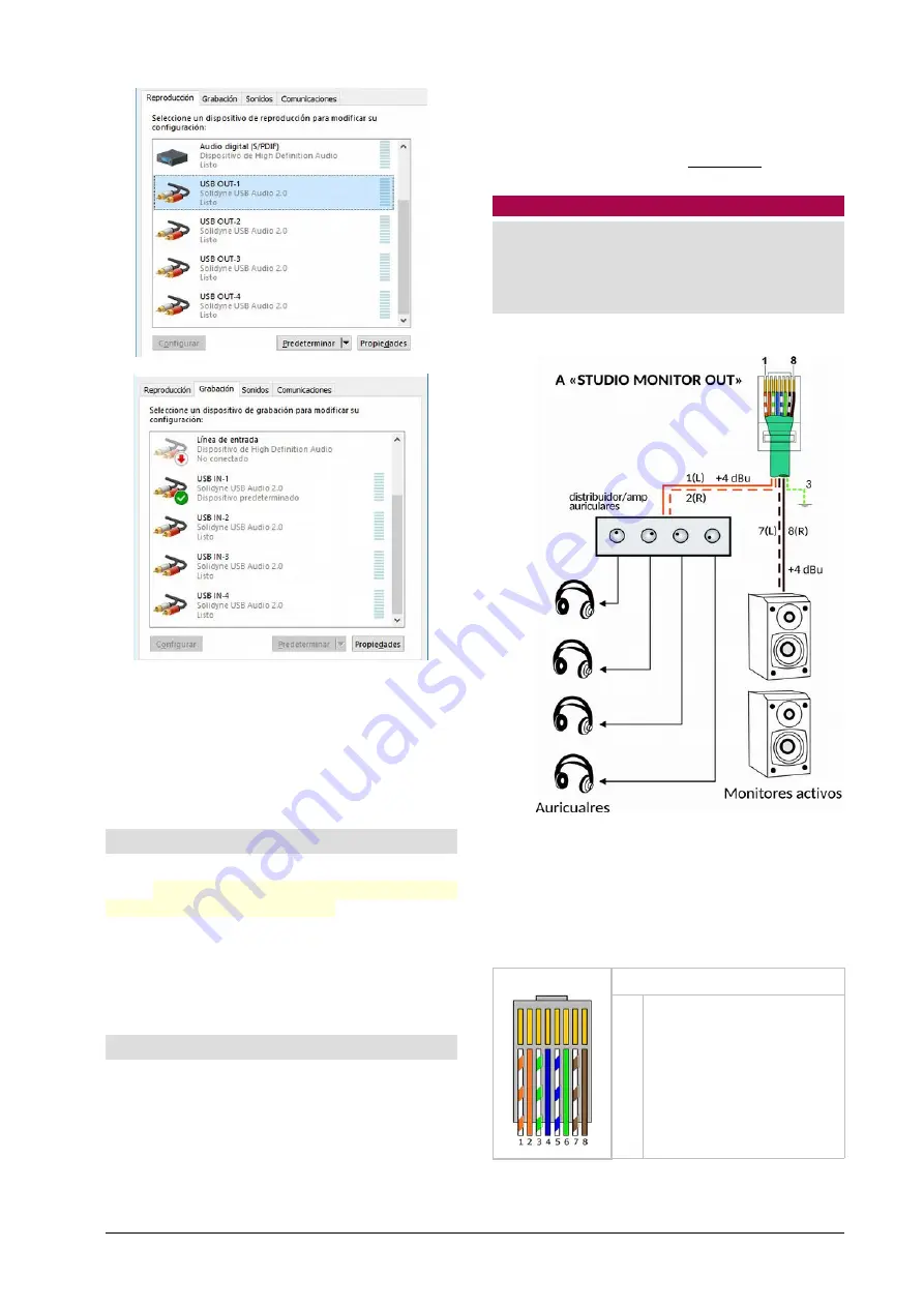
Figure 1: Connections for monitor speakers and headphones at the Studio,
using the adapter patch cord and a standard headphones amplifier.
The connection is made with a “STUDIO MONITOR”
adapter cable supplied from factory. The signal dia-
gram is as follows:
RJ-45
STUDIO MONITOR OUT
1
2
3
4
5
6
7
8
Headphones, left (+4 dBu)
Headphones, right
GND
ON-AIR (+14 V)
Talckback to Control Room
VCC + 14 V
Speakers, left (+4 dBu)
Speakers, right
*Chassis = GND
www.SolidynePro.com
Solidyne UNIDEX UX24
Page 13


