background image


© CASWA Pty Ltd – 2017 


12 | Page 


6.1


WEB PORTAL SETUP 

IMPORTANT: 

The Web Portal Setup Only applies to

 LIFTLOG 

and 

ACCESSPACK 

products, if you are 

trying to set up alerts from a different device please skip to step 6.2. 

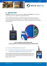
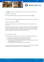
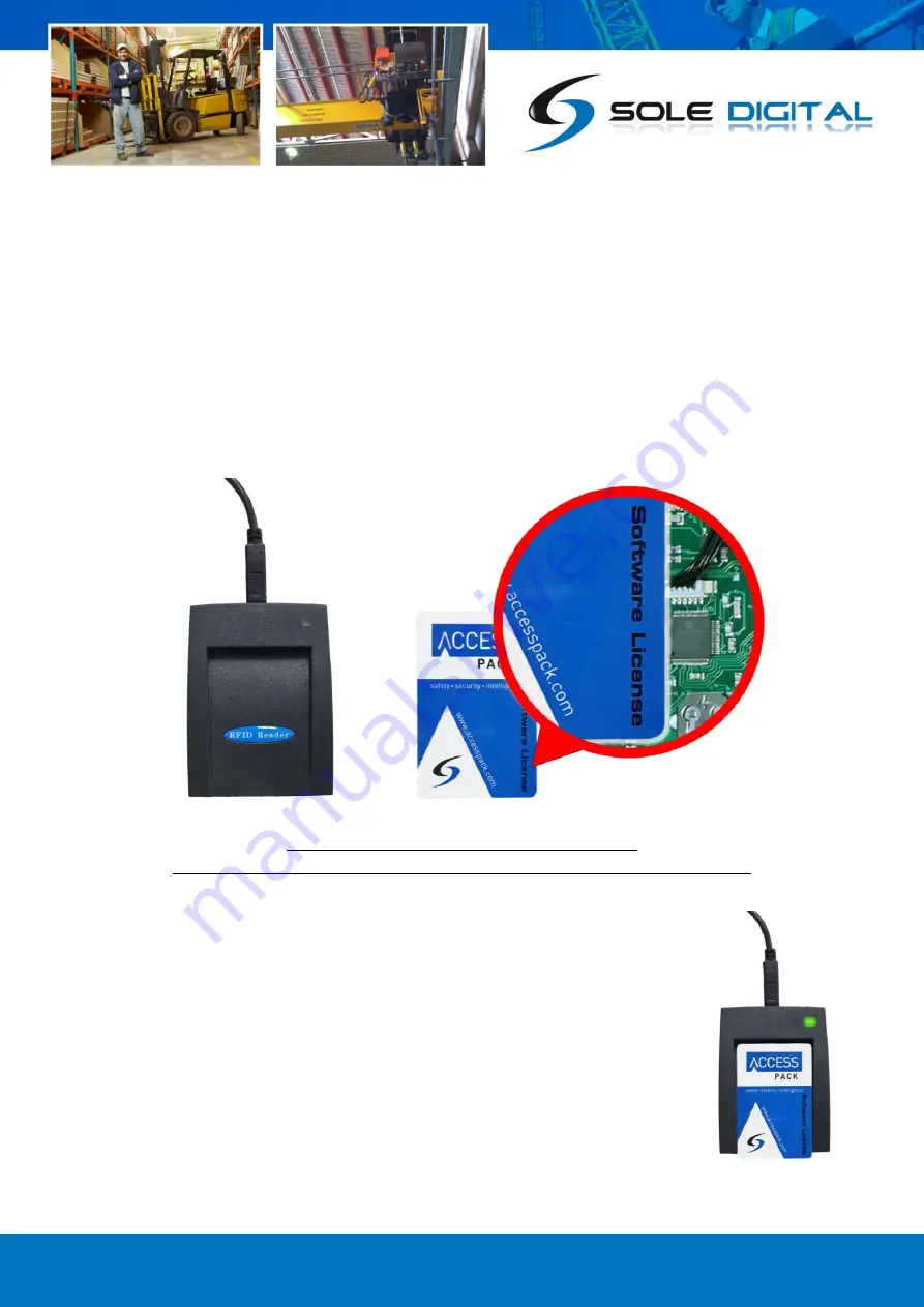
For this method you will need to grab your RFID card reader, USB Type B Cable, and Software 
Licence Access Pack Card. The Software Licence card is different to your regular Accesspack card, 
and can be identified via the words “Software Licence” along the right hand side, as demonstrated in 
the diagram below.  


Figure 6: RFID Reader and USB-TYPEB Cable (Left) 

AccessPack Software Licence Card with Distinguishing Feature Highlighted (Right) 


6.1.1


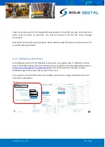
Plug-In your RFID Card reader into a PC 

6.1.2


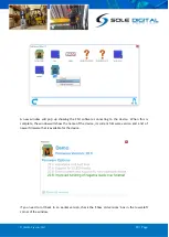
Once powered up place your Software Licence card into the     
card reader, as indicated by the diagram on the right. 

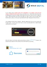
Note: If the light on the RFID doesn’t turn Green upon presentation of your card it 
may mean that you have not downloaded the CASWA.Cardreader software. If this 
is the case please proceed to the next step. If your card does register right away 
feel free to skip to step 6.1.5.  

Summary of Contents for STL100

Page 1: ...CASWA Pty Ltd 2017 1 Page LINK 4 Wireless Crane Gateway Model STL100 STL100W Installation and User Manual Revision 03 June 2022 CASWA Pty Ltd 2021...

Page 2: ...M CARD REFRESH 11 6 SETTING UP REAL TIME ALERTS ON YOUR DEVICE 11 6 1 WEB PORTAL SETUP 12 6 1 1 Plug In your RFID Card reader 12 6 1 2 Hold your Software Licence card over the card reader 12 as indica...

Page 3: ...CASWA Pty Ltd 2017 3 Page...

Page 4: ...to the internet so you can store your data on the cloud and gain real time analysis of how your devices are being operated All of our Hoistnet devices such as Liftlog and MaxOut transmit their data v...

Page 5: ...CASWA Pty Ltd 2017 5 Page 2 SPECIFICATIONS 2 1 Physical Specifications Overall length mm 198 Overall width mm 132 Overall height mm 38 Weight kg 0 2 Mounting Adhesive Velcro Figure 2 Case Dimensions...

Page 6: ...2 Electrical Specifications Parameter Description Min Typ Max Units Vin Supply voltage 5 VDC Iin Supply current 1 A Operating Temperature 40C 85C C Note Extended operation at maximum temperature will...

Page 7: ...ore installing your Link 4 device visually inspect the device and check that a the type of input marked on the front of the device is appropriate for your application b the case is not damaged and fit...

Page 8: ...can be included upon request To begin the installation process simply plug your adaptor into a wall outlet and then into the Link 4 unit via the round power input on the bottom as demonstrated in the...

Page 9: ...ind a 4G signal to broadcast on If you see a Red Light upon startup though this will be normal Please refer to section 4 3 for further guidance on the startup procedure for the Link 4 BLUE LIGHT Conne...

Page 10: ...owing steps If you disconnect Link 4 from its power source the device will recycle through these steps If the device remains in the RED phase for longer than 3 minutes check to make sure your Link 4 h...

Page 11: ...t Sole Digital to determine the cause of the fault Note If you have purchased your Link 4 in one country but are moving to another country and are hoping to use the Link 4 in that country you must con...

Page 12: ...ware Licence along the right hand side as demonstrated in the diagram below Figure 6 RFID Reader and USB TYPEB Cable Left AccessPack Software Licence Card with Distinguishing Feature Highlighted Right...

Page 13: ...eader setup link 3 Once you double click on the link the program will begin downloading Figure 7 How to Download the Card Reader Software 6 1 4 Installing the Software Upon opening the Caswa CardReade...

Page 14: ...econds to populate and the light on your RFID reader will begin to oscillate between Green and Red Once the inspector has been populated with your devices in the left hand side panel remove your card...

Page 15: ...ur example receives a G Force shock through a collision Note Impact Detection may not be available on your device depending on which device you have installed Simply click each scenarios checkbox you...

Page 16: ...rvice Utility software If you already have the FSU installed on your computer feel free to skip to step 6 2 2 If you haven t currently got the FSU installed on your computer continue on step 6 2 1 6 2...

Page 17: ...been installed onto your computer double click on the FSU program icon 6 2 3 Connecting to the MaxOut Upon opening the FSU program will automatically use the Link 2 to scan for all of the Bluetooth en...

Page 18: ...2 5 appears then you can skip past step 6 2 If the MaxOut does not bring up that interface it likely means you will require a firmware update for your MaxOut in which case please continue onto step 6...

Page 19: ...to the device When this is complete the window will show the name of the device its current firmware version and a list of newer firmware that is available for the device If you need to roll back to a...

Page 20: ...CASWA Pty Ltd 2017 20 Page Select a firmware version and then press the Apply firmware button that appears in the lower right corner of the window The display will change to the following...

Page 21: ...ith the old display and select button can be recovered from a failed firmware update on site by powering the MaxoutDX while holding down the select button The old display will show the text Reflash Wh...

Page 22: ...ng the device 6 2 5 Setting Your Parameters All configuration options for the MaxOut are now shown on a single screen To calibrate the other parts of the MaxOut please refer to the MaxOut manual avail...

Page 23: ...month in contrast to an office environment in which case the following steps will only need to be carried out once every 6 months Our recommendations are to Check the device for dirt and grime and wi...

Reviews: