


INSTALLATION
19
Operator’s Manual Marine Diesel Gensets
Revision 2. 10/2017
Section 3 – Installation
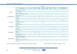
3.1. Angle of Installation
Make sure the genset is installed on a level surface. Otherwise, the following angular
operation maximum is permitted:
If the genset operates in these conditions, check Section 5.4. Lubrication System.
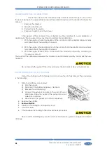
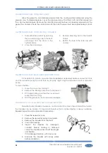
3.2. Genset installation
Follow these steps to install the genset:
1.
FIX GENSET.
See 10.4 Genset Dimensions (mounting holes) and section 9 Tightening Torques.
2.
CONNECT EXHAUST OUTLET.
See 10.4 Genset Dimensions.
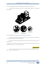
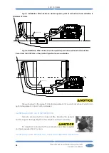
1.
WET EXHAUST OUTLET
2.
DRY EXHAUST SEAWATER OUTLET
3.
CONNECT SIPHON
BREAKER.
(if installed) See 10.4 Genset Dimensions.
4.
CONNECT SEAWATER INLET.
See 10.4 Genset Dimensions.
5.
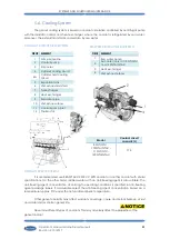
CONNECT FUEL INLET.
See 10.4 Genset Dimensions.
6.
CONNECT LEAK COOLANT OUTLET.
See 10.4 Genset Dimensions.
7.
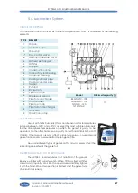
FILL WITH OIL.
See 5.4 Lubrication System.
8.
FILL WITH COOLANT.
See 5.6 Cooling System.
9.
CHECK EACH PIPE CONNECTION
for oil or coolant leaks.
10.
CONNECT TO EARTH.
See 5.5 Fuel System.
11.
PRIME THE FUEL SYSTEM.
See 5.5 Fuel System.
12.
CONNECT TO SCO PANEL.
See Section 10.4 Genset Dimensions.
13.
CONNECT TO BATTERY.
Follow label battery connection into the genset.
It is necessary to install a waterlock (supplied as accessory) in the exhaust system to avoid
water ingestion (See section 6.7).
Model
Continuously
85 GT/GTC - 100 GTA/GTAC - 115 GT/GTC -
120 GTA/GTAC
10º
Summary of Contents for 100 GTA
Page 1: ...U_GNBL_EN Rev 2 ...
Page 2: ...INTRODUCCION 2 Operator s Manual Marine Diesel Gensets Revision 2 10 2017 ...
Page 56: ......
Page 58: ......
Page 66: ......
Page 67: ......
Page 68: ......
Page 69: ......
Page 70: ......
Page 75: ......