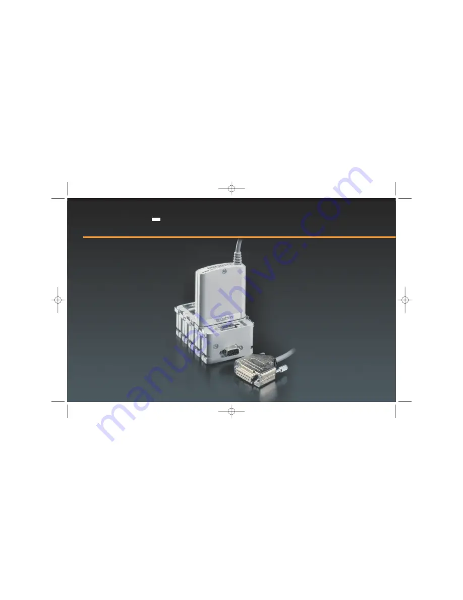
Digital Input/Output Module
solartron
Manual No. 502237
Issue 2
DIOM 502237_Issue 2.qxd 20/07/2005 15:38 Page fcov1
Page 1: ...Digital Input Output Module solartron Manual No 502237 Issue 2 DIOM 502237_Issue 2 qxd 20 07 2005 15 38 Page fcov1...
Page 2: ...s document may be reproduced or transmitted in any form or by means electronic or mechanical for any purpose without the express permission of Solartron Metrology 2000 Solartron Group Ltd All rights r...
Page 3: ...onnections Pins 9 to 12 DIOM connector 11 I O Port Output Specification Driver Configuration Using Orbit Supply 12 I O Port Output Specification Logic Configuration 13 3 0 Communication with the DIOM...
Page 4: ...Input Output line are connected via a 0 5 meter flying lead and a 15 way D type connector This Manual The manual describes the technical specification of the product enabling you to connect to the DIO...
Page 5: ...ndicates where applicable cautionary or other information is to be found WARNINGS Do not operate in an explosive atmosphere To avoid explosion do not operate this equipment in an explosive atmosphere...
Page 6: ...below the SELV and is therefore outside the scope of the Low Voltage Directive DIOM General Specification Module Temperature 20 C to 70 C 4 F to 158 F except where specified Module Supply from Orbit N...
Page 7: ...environment The above compliance statements is for representative system Layout of cables supply sources and electrical environment may affect performance IP Rating IP53 when mounted in an upright po...
Page 8: ...er Pin Label pin 1 I O bit 0 pin 8 I O bit 7 pin 2 I O bit 1 pin 9 0 V pin 3 I O bit 2 pin 10 0 V pin 4 I O bit 3 pin 11 0 V pin 5 I O bit 4 pin 12 0 V pin 6 I O bit 5 pin 13 5 V pin 7 I O bit 6 pin 1...
Page 9: ...e 1 35 V Absolute Maximum Ratings VIH MAX 30 V VIL MIN 0 5 V IIL 1mA source Note Output driver MUST be set high logic 1 using the OrbitPreset command before using the port as an input 2 0 Detail Speci...
Page 10: ...assuming 8 outputs used at 100 duty cycle Open drain Low level output voltage 0 2 V Absolute Maximum Ratings Each Output VOH MAX 30 V VOL MIN 0 5 V IOL 50 mA sink 2 0 Detail Specification 2 0 Detail...
Page 11: ...t be connected to a local 0V Load 0V This prevents the load 0V current returning through pins 9 12 on to the orbit network Maximum difference between Orbit 0 V and Load 0 V 0 5 V 2 0 Detail Specificat...
Page 12: ...from the Orbit supply via the DIOM This can be used for external loads such as active switches indicators and sensing devices Open drain Low level output voltage 0 2 V Absolute Maximum Total IOrbit M...
Page 13: ...riving typical 5V logic inputs High level voltage VH 4K7 internal pull up to Orbit 5 V Low level voltage VL 0 2 V 50mA max sink 2 0 Detail Specification 2 0 Detail Specification 11 Manual No 502237 Is...
Page 14: ...n reset all Orbit Modules Type broadcast Parameters card channel Will reset ALL the Orbit Modules on a network at the same time To set the Orbit Modules to the required Baud rate this command MUST be...
Page 15: ...identity ID during manufacture When used on a network it is more efficient to use a shorter temporary ADDRESS stored in the Orbit Module memory this is a number between 1 and 31 This command is used...
Page 16: ...er show the state of the input pins Each pin must first be set high via OrbitPreset if it is to be used as an input A low state on the input pin will be returned as a logic low 0 a high state on the i...
Page 17: ...0 will turn the output driver on the output pin will be set low 0V A logic high 1 bit will turn the output driver off the pin will be pulled up to Orbit 5V via 4K7 and series diode or external load if...
Page 18: ...ess module type hardware type resolution module info Will return information about the type of module and or probe Using the OrbitIdentify command may return additional information 3 0 Communication w...
Page 19: ...ress Performs software reset on a particular Orbit Module The Orbit Module will then need to be re addressed Allow at least 0 5 second for completion of the command 3 0 Communication with the DIOM 3 0...
Page 20: ...tive loads must be suppressed i e protection diode 0V load must be connected to local 0V to minimise load return current through DIOM and Orbit 4 0 Application Hardware 4 0 Application Hardware 18 Man...
Page 21: ...han normal interference sources i e near heavy industrial machinery Adopting some or all of the following measures may enhance immunity performance Shielded cable Braided 360 screen to shell Ferrite s...
Page 22: ...back correctly except the last where Port 0 bit 0 output driver is switched ON causing a false input state to be read by the Port 0 input buffer Input and output ports are internally connected For eac...
Page 23: ...5 0 Application Software 5 0 Application Software 21 Manual No 502237 Issue 2 DIOM 502237_Issue 2 qxd 20 07 2005 15 38 Page 21...
Page 24: ...port is being used to read a switch condition for example a single OrbitRead1 may have missed the event or may have seen a noise spike in the place of the event A possible solution is to issue multip...
Page 25: ...ct s and the circumstances of the failure 4 Name and telephone number of the person to contact if there are questions about the returned product s 5 Statement as to whether warranty or non warranty se...
Page 26: ...PO22 9ST Tel 44 0 1243 833333 Fax 44 0 1243 833332 U S A Solartron Metrology 10770 Hanover Road Forestville NY 14062 Tel 1 716 965 4100 Fax 1 716 965 4144 Solartron pursues a policy of continuous dev...