65
en
8�3
Configuration
The expansion port can be configured via the web interface of the MaxWeb Portal:
1. Log in to the MaxWeb XPN (see
).
2. Open the “Devices > External devices” menu.
3. Activate the connected sensors, enter the data of the sensors and confirm with “OK”.
For a detailed description, see
.
8�4
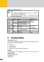
Inputs for external alarm sensors
Connect switching contacts as external alarm sensors to the terminals IA and IB of the
expansion port on the back of the MaxWeb XPN. The alarm sensors can be used for moni-
toring the function of a fan or an AC isolating switch, for example.
An activated switching contact that is closed continuously during the delay time
will trigger an alarm. The alarm is configured as shown in “Alarms > Settings”
(see
). Alarm signals are transferred as “Error” or “Failure”.
Note
The external alarm inputs are unsuitable for personal protection or safety-rel-
evant applications. SolarMax Produktions GmbH cannot accept liability for
missing, late or incorrectly transferred alarm signals
8�5
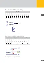
Terminal assignment
8�5�1 Terminal assignment on the front of the MaxWeb XPN
Note
V + corresponds to the supply voltage of the device within a range of 15 … 24 V,
with respect to GND, and is secured with a resettable fuse of 0.2A.


