background image

December 2020 

|

 Solar Stik

®

, Inc.

20 

|


System Setup and Operation Manual for the Solar Stik G-BOSS E Light HPS

PRELIMINARY

Figure 5. Inter-Connect Plug

The Standard Inter-Connect Plug

• 

Polarized 

• 

200 A maximum current

• 

24 VDC connection only

• 

Mechanically “locks” into place 

• 

Rotate knob clockwise to lock, 
counterclockwise to release 

• 

Can be repaired or modified in the field

Summary of Contents for G-BOSS E LIGHT

Page 1: ...k Inc PRELIMINARY SYSTEM SETUP OPERATION AND MAINTENANCE MANUAL FOR THE SOLAR STIK G BOSS E LIGHT HYBRID POWER SYSTEM Version 1 0 Updated 20201209 DISTRIBUTION STATEMENT A Approved for public release...

Page 2: ...Manual Functions 12 UPS Automatic Functions 13 The HPS Architecture Function and Operation 13 Energy Storage The Foundation of the HPS 13 Minimum Battery Capacity Required for Optimal System Operation...

Page 3: ...44 i Connect PRO Verter to 120 VAC Loads Optional 45 j Connect Loads Requiring Regulated 28 VDC Output Optional 45 k Connect PV Array s to PRO Verter Optional 46 3 System Activation and Initialization...

Page 4: ...Settings Menus 71 TROUBLESHOOTING PROCEDURES PRO Verter System Troubleshooting Generator Fault Failure 73 Clearing PRO Verter Faults 73 System Recovery with Overdischarged Batteries 73 PRO Verter Fau...

Page 5: ...ure 24 Working space distance for the PV Array and the PRO Verter 33 Figure 25 G BOSS E Light connection diagram and kit inventory 34 Figure 26 PRO Verter to ESM connections for G BOSS E Light 35 Figu...

Page 6: ...D Card from PRO Verter User Interface 60 Table 12 Fault Messages Symptoms and Troubleshooting 74 Table 13 Symptoms and Solutions for the Most Common Power Hub Issues 78 Table 14 24VDC PRO Verter S 300...

Page 7: ...battery and ensure uninterrupted power to the loads The battery becomes the foundation of the HPS and the architecture is opened to allow multiple technologies to operate in concert Generator Load Fue...

Page 8: ...liquids Close and latch and or lock the cases when the components are unattended Exercise caution when handling or operating the System Live power may be present Safety Information Labels Your safety...

Page 9: ...s data processing centers labs and telecommunication rooms Using the Fire Extinguisher When using the extinguisher on a fire remember PASS Pull the pin Aim the nozzle or hose at the base of the fire f...

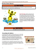
Page 10: ...the main breaker panel of the grid power Any generator connected to the System must have a neutral to ground bond Grounding the System PRO Verter Grounding Lug Figure 1 PRO Verter grounding lug Electr...

Page 11: ...latched During operation cases should be placed upright especially during inclement weather Lids should be open only to access operator controls and closed at all other times Impact Equipment should...

Page 12: ...conditions The Continuous Load AC power requirement is LESS than the individual Inverter or Generator Grid AC power output ratings In the Hybrid model the PRO Verter serves as the primary power manag...

Page 13: ...uninterrupted pure sine wave AC and DC power to the loads It is a powerful solution for the following conditions 1 The generator requires protection from adverse operating conditions 2 Grid or generat...

Page 14: ...multiple Expander Paks must be connected to a PRO Verter for the System to function at its rated power The combined values of the Expander Pak circuit breakers must be greater than the rated inverter...

Page 15: ...eries only after the load is fully supported by the generator Real time Load Management When connected to an active AC source the PRO Verter can automatically adjust in real time its battery charging...

Page 16: ...source generator or grid utility Load AC power demand is greater than the AC INPUT setting which may cause the PRO Verter to disconnect from the AC source when in pass through charging mode Load AC an...

Page 17: ...luding advanced power distribution and management modules stacking of generators with PRO Verters Power Hubs and more Consult the individual product manuals for additional information about scaling an...

Page 18: ...Plug Play architecture allows expansion or contraction of battery capacity when conditions warrant Use Inter Connect Strips and Inter Connect Cables to create a bank of Li Expander Paks Figure 26 Not...

Page 19: ...aced throughout the circuit It ensures the potential for a reverse polarity connection within the circuit is minimized If a problem occurs in a leg of the Inter Connect Circuit the affected leg will d...

Page 20: ...Stik G BOSS E Light HPS PRELIMINARY Figure 5 Inter Connect Plug The Standard Inter Connect Plug Polarized 200 A maximum current 24 VDC connection only Mechanically locks into place Rotate knob clockwi...

Page 21: ...24 VDC bus and converts it to stable regulated 28 VDC output The PDM protects equipment that is sensitive to voltage fluctuations The case does not open Figure 6 PDM front Figure 7 PDM left side The...

Page 22: ...on the right side of the PDM 3000 provides regulated 28 0 VDC power to the G BOSS Power Distribution Unit PDU The 100 A breakers on the right side also serve as power switches for engaging and diseng...

Page 23: ...23 December 2020 Solar Stik Inc System Setup and Operation Manual for the Solar Stik G BOSS E Light HPS PRELIMINARY PDM Information Plate I Plate Top Figure 10 PDM top I Plate specs and cautions...

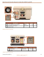
Page 24: ...t Ethernet RJF21B D Exhaust Vent B C D Figure 11 Overview of Power Hub connections Expander Pak Power Hub Ethernet 24 VDC Input Output Unregulated DC Solar Inputs Regulated DC Power Inputs Overview Fi...

Page 25: ...cle CB2 22 2SC 1166 W Max Solar Charger 3500 W Total 60 A 58 VDC 11 7 A 100 VDC A A Neg C Pos B N A B Description Connector Amps Voltage A 24 VDC NATO Slave unmetered NATO Slave 100 24 VDC B Regulated...

Page 26: ...d on the I Plate The Warning and Notices are important lists of things to do and not to do Be familiar with their content before operating the Power Hub An I Plate is usually tailored to a customer s...

Page 27: ...e and the Inter Connect Cable storage ports Recommended safety equipment PV charging specifications compatible battery chemistries environmental operating conditions and Solar Stik Technical Support c...

Page 28: ...tage Amps A 24 VDC IN OUT Inter Connect Port 24 VDC 200 B 24 VDC NATO Slave unmetered NATO Slave 24 VDC 100 C GEN Comm Ports 1 2 Amphenol HA100001 02 36 C Solar Only Port Cannon Bayonet Receptacle CB2...

Page 29: ...scription Connector Voltage Amps A 120 VAC GENERATOR Input Connection Marinco 125 30 B 120 VAC GRID Input Connection HBL61CM65 125 20 C Exhaust Vent Cover A C Figure 20 PRO Verter right side B A B Des...

Page 30: ...rter when the System batteries have been overdischarged Connect the PRO Verter to a 120 VAC power source Press and hold the System Recovery button Turn on the PRO verter user interface Continue pressi...

Page 31: ...cuit breakers protect against overcurrent conditions in dedicated circuits If too much amperage flows due to short circuit inadequate or improper loading or component failure these will protect the sy...

Page 32: ...ed press and hold ENTER to save ix Press DOWN button to arrive at GEN MAX CURRENT x Repeat steps v through viii 4 Initiate System cycling a Toggle Generator Control switch es to ON position Once gener...

Page 33: ...hed capacity and efficiency of the components OPERATOR INSTRUCTIONS ALL Solar Stik equipment is designed for operation in adverse conditions however certain rules apply 1 If operating in wet environme...

Page 34: ...tem Component 20 0104029 24VDC PRO VERTER S 3000 120 EBA2 1 20 0002510 DC POWER DISTRIBUTION MODULE 28V REG 1 20 0302206 24VDC POWER HUB 3500 1 20 0702604 PRO Verter RMK AGS 1 2 Connect System Compone...

Page 35: ...rip s to the PRO Verter a Connect PRO Verter to Energy Storage Modules Figure 26 PRO Verter to ESM connections for G BOSS E Light 24 VDC ESMs Inter Connect Strip B E E E E E E 24VDC PRO Verter S 3000...

Page 36: ...s Figure 27 PRO Verter s to AC power input connections PRO Verter S 3000 right side 120 VAC 60 Hz grid power OR 120 VAC 60 Hz fuel powered generator 1 5 kW May be paralleled May be paralleled Compatib...

Page 37: ...831A and MEP 802A Gen Comm Cable connections PRO Verter GEN COMM port specificity Defender Ranger MPG single operation Connect to Gen Comm 1 or 2 port Defender Ranger MPG tandem operation Connect to G...

Page 38: ...kW and Ranger 2 kW MPGs Use Gen Comm ports 1 and or 2 on the front of the PRO Verter and the communication port on the generator using the 25 Ranger Defender Gen Comm Cable Figure 30 Defender 1 kW and...

Page 39: ...d to a single power input port on the left side of the PRO Verter Figure 27 The mode of each generator is controlled independently and each has its own communication cable to the PRO Verter The LED ov...

Page 40: ...ar Stik G BOSS E Light HPS PRELIMINARY d Connect PRO Verter to Power Hub 3500 Use a 5 Inter Connect Cable A to connect the PRO Verter to the Power Hub 3500 using the ports illustrated in Figure 32 Pow...

Page 41: ...n PDM 3000 Power Hub 3500 Use an Inter Connect Cable A to connect the Power Hub 3500 to the PDM 3000 using the ports illustrated in Figure 33 The Inter Connect ports on the left front of the Power Hub...

Page 42: ...Light HPS PRELIMINARY f Connect PDM 3000 to PDU and Tower Figure 34 PDM to tower and PDU connections Tower F G PDM 3000 Use cables F and G to connect the PDM 3000 to the Tower and PDU respectively Th...

Page 43: ...y port Note there are three 3 solar chargers in the Power Hub 3500 Both ports of a single charge controller are equal Distribute the power from PV arrays equally among the three 3 solar chargers when...

Page 44: ...significantly reduce their functional life expectancy Detailed instructions for securing the PV arrays are found in the 450W Expedition PV Array Operator Manual and the Solar Stik 400 Operator Manual...

Page 45: ...oad power switches to prevent power draw during System setup Figure 36 PRO Verter AC power output ports j Connect Loads Requiring Regulated 28 VDC Output Optional REGULATED 28VDC OUPUT Connect loads t...

Page 46: ...r specifications for PV arrays PV arrays other than the ones provided in the kit can be connected to the PRO Verter as long as the power specifications for the arrays do not exceed the specifications...

Page 47: ...clock Note Password is not required for setting this parameter Select Group TIME SETTING Enter the time 2019 11 11 00 00 Home Screen 3 System Activation and Initialization a Activate the HPS i Turn o...

Page 48: ...INPUT SETTING GRID MAX CURRENT 20 00A INPUT SETTING Home Screen Select Parameter INPUT SETTING GEN MAX CURRENT 20 00A GS Information System Con guration Re uirements Operation of a Hybrid System When...

Page 49: ...the ON position manually signals the generator to start using the PRO Verter AGS controls The green status LED will be steady ON OFF When the AGS switch is placed in the OFF position the LED status in...

Page 50: ...er interface before disconnecting batteries Press and hold user interface ON OFF button for five 5 seconds then release The user interface will turn off 4 PDM 3000 PDU and or Tower Operation After the...

Page 51: ...nder ONLINE MODE only Option 2 Charger Only Provides charging and pass through when the AC input is available The PRO Verter inverter is inactive when AC input is not available PRO Verter Operating Mo...

Page 52: ...W PF 60 00 Hz PF 60 00 Hz PF PF 1 00 PF 60 00 Hz EVO 2224 Battery External Standby 120 0V 0 0 A 0 0 A EVO 2224 Battery Heat sink Transformer Standby 25 0 C 25 0 C 25 0 C EVO 2224 Battery Heat sink Tr...

Page 53: ...to upper menu screen in various menu maps Down Move from upper to lower menu screen in various menu maps Enter right arrow Select write a particular value or option Access programmable settings Status...

Page 54: ...power On Off button is pressed for 5 s On On Normal charging Flash 1 time sec Off Equalization charging Flash 2 times sec Off Inverting discharging Alarm beep 3 sec default off On Off Low battery ala...

Page 55: ...ciated value can be changed Pressing the BACK key will exit to the previous level There is a 30 second time out for setting parameters after 30 seconds the setting mode will be cancelled and the displ...

Page 56: ...T LOW LIMIT Parameters for grid generator input low voltage level Group 4 INPUT HIGH LIMIT Parameters for grid generator input high voltage level Group 5 OTHER FUNCTION Power Saving Alarm Remote Switc...

Page 57: ...off the inverter Battery voltage must be at the low voltage set point for this period of time before the inverter shuts off LV CUT OFF TIME 3600 sec This timer shuts off everything including the charg...

Page 58: ...input frequency falling below Low Cut Off SYNC GRID 0 Fine Sets syncing algorithm for AC input 0 Stable AC Input 1 not Stable AC input SYNC GEN 0 Fine Sets syncing algorithm for AC input 0 Stable AC...

Page 59: ...which the low AC input voltage Cut Off 3 is allowed Input Low Limit Programmable Settings Table 7 Parameters for Grid Generator Input Low Voltage Level GROUP 4 INPUT HIGH LIMIT Parameter Setting Value...

Page 60: ...n Inverting mode DEFAULT RESET 0 NO This is to reset all of the parameters to the factory values The factory values are not the program values set by Solar Stik DATA LOG TIME 2 10 sec A real time cloc...

Page 61: ...UNCTION Select Parameter OTHER FUNCTION POWER SAVING 0 Disable ENTER key DOWN key x 4 ENTER key DOWN key x 10 Password key in 0000 Select Parameter OTHER FUNCTION PARAMETER SAVE 0 No Saved file end EN...

Page 62: ...er interface s internal real time clock Available options for Data Log Time are 0 Disable 1 1 sec default 2 10 sec 3 30 sec 4 60 sec 5 5 min 6 10 min Events and Error Codes are recorded as soon as the...

Page 63: ...l to the programmed value of Data Log Time Note Event Error Codes will be logged as soon as they occur Follow procedure given below to open Data Log Files in Excel Start Excel Click File Microsoft Off...

Page 64: ...System Setup and Operation Manual for the Solar Stik G BOSS E Light HPS PRELIMINARY Text Import Wizard Step 2 will appear Choose Semicolon and click Finish button Text Import Wizard Step 1 will be sh...

Page 65: ...65 December 2020 Solar Stik Inc System Setup and Operation Manual for the Solar Stik G BOSS E Light HPS PRELIMINARY Data will be displayed on a worksheet with the log data stored in columns and rows...

Page 66: ...the PV arrays System battery bank voltage Net current flowing to or from the System batteries Depending on how the System is configured the LCD shows capabilities that may or may not be utilized by t...

Page 67: ...he user interface to navigate submenus under the menu items on the device list Menu Button Note The charging current reported may be at or near 0 0 A when the batteries are charged fully even if the P...

Page 68: ...Charger 1 Time PV Battery Total yield System yield Load Error Parallel operation status Parallel operation Daily history Overall history Device 0 0W 0 0Ah 0 0kWh 0 0kWh 0 No error On Standalone Off 0...

Page 69: ...age alarm High starter voltage alarm Low state of charge alarm Low battery temperature alarm High battery temperature alarm Mid voltage alarm High charge current alarm High discharge current alarm Cel...

Page 70: ...Power Hub battery monitor will also approach zero 0 A as the batteries approach a fully charged state DEVICE LIST Battery Monitor Time 100 0 0A 0 0W Solar Charger 1 Solar Charger 2 Solar Charger 3 Ba...

Page 71: ...Solar Charger 3 Notifications Settings Firmware Time Firmware version Build date time Online updates Offline updates Stored backup firmware v2 03 201702271607 Display Language Time Display off time Sh...

Page 72: ...tected data cards Add data cards manually TCP port Press to scan 0080 Wireless AC sensors Time No gateway Ethernet Time Unplugged State Wi Fi Time No Wi Fi adapter connected GPS Time Status Latitude L...

Page 73: ...e until the fault is cleared A short press 0 1 seconds of the On Off key will clear the Fault Message and the PRO Verter will return to the operational status if the reason for the fault condition has...

Page 74: ...and the alarm in PRO Verter will now beep steady If the Battery low voltage fault condition is not reset within the LV Cut Off Time the PRO Verter will shut down completely after the LV Cut Off Time L...

Page 75: ...e Input current Charging Current Pass Through Current to the load is 1A more than the set threshold of GRID MAX CURRENT GEN MAX CURRENT for 5 seconds current is sampled every 33 3 s There will be no A...

Page 76: ...ed off and will require manual reset by powering off waiting for 1 minute and then powering on again Note If there is short circuit condition in Charging mode i e when AC input is available short circ...

Page 77: ...y there is no blockage of air suction and discharge vents adequate cool replacement air is available and the ambient temperature is within the limits Reduce the load and Bulk Current The fault will be...

Page 78: ...nt device Normal operation Read battery SOC from primary management device e g PRO Verter Not registering charge current with panels operating in sun 1 Power Hub overheated 2 Batteries fully charged 2...

Page 79: ...id installation where an SD card is used first upload the data file Adding a Power Hub Installation is only possible after the VRM Portal has received the first data transmission from the Power Hub us...

Page 80: ...sed in Menu Device List Notifications These historical records can assist in troubleshooting and maintaining peak performance of the Power Hub and connected components such as PV arrays and batteries...

Page 81: ...ily for whatever reason but this also means when the data file has been uploaded to VRM it needs to be renamed or cleared from the micro SD card before reinserting otherwise the data will be transmitt...

Page 82: ...r will not auto reset Err 6 Err 7 Remote battery voltage sense failure Check if the V sense connector is properly connected to the battery terminals Most likely cause the remote V sense connector is c...

Page 83: ...urrent The current from the PV panel array has exceeded 75 A This error could be generated due to an internal system fault Disconnect the Power Hub from all power sources wait 3 minutes and power up a...

Page 84: ...bration data lost If the unit does not work and error 116 pops up as the active error the unit is faulty Contact Solar Stik Technical Support If the error is only present in the history data and the u...

Page 85: ...sh with water and dry the filter Reinstall 3 If the filter is damaged or cannot be cleaned replace If the filter cannot be cleaned is too damaged to function properly and a replacement is not immediat...

Page 86: ...it by rinsing it with water to remove the particulate matter and dry it Replace the filter if it is crushed rotted or cracked as illustrated in the left column of Figure 51 Spare filters may be stored...

Page 87: ...ed to function properly and a replacement is not immediately available the unit is partially mission capable Replace the filter as soon as possible to restore the unit to fully mission capable 1Clean...

Page 88: ...and missing items 2 Clean excessive dust or dirt accumulation from the exterior interior and connectors 3 Close all unused port covers If the case is broken or split or if connectors are damaged do n...

Page 89: ...allow the case to be sealed to prevent damage to the internal components from environmental factors Additionally two 2 sets of steel reinforced holes one 1 in the lid and one 1 in the base of the case...

Page 90: ...briefcase using the case handles arrows The PRO Verter has wheels and an extendible pull handle enabling it to roll easily on appropriate surfaces There are no transport restrictions for these compone...

Page 91: ...of such Products the Products shall be free from defects in materials and workmanship and shall conform to the contractual specifications or to specification sheet of the Product This warranty does n...

Page 92: ...December 2020 Solar Stik Inc 92 System Setup and Operation Manual for the Solar Stik G BOSS E Light HPS PRELIMINARY...

Page 93: ...ort of small scale renewable energy power generation systems with detailed explanation of system components Advanced configuration options with hands on deployment of actual systems will enhance stude...

Reviews: