User Guide
Manual/Automatic Transfer Switch Coupling
DANGER
ELECTRICAL SHOCK AND FIRE HAZARD
Installation must be done by qualified personnel to ensure compliance with all applicable installation
and electrical codes and regulations. Instructions for installing the Vulcan unit are provided here for
use by qualified personnel only.
Failure to follow these instructions will result in serious injury or death.
There are instances where a Vulcan system may be tied into the building infrastructure
wiring/circuits that connect to critical loads for backup. When this configuration is desired,
Vulcan can be coupled into building circuits using a manual or automatic transfer switch that
switches the load between grid/shore power and Vulcan power. The transfer switch has two (2)
input connections and one (1) output connection. It connects between the load center/main
breaker panel and load wiring, and the Vulcan 120Vac output.
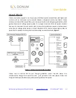
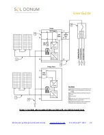
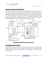
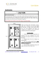
Figure 9.,
illustrates a manual
transfer switch configuration schematic suitable for use with the Vulcan system.
In this configuration, a 2kW Vulcan system is connected to a 20A circuit that is fed through its
internal 30A automatic transfer switch (ATS). The Vulcan inverter operates in standby mode and
will switch to battery power if grid power sags below 90Vac or is lost.
The manual transfer switch has three (3) load power settings:
●
Line
: Feeds grid/shore power to the load circuits
●
Off:
Turns off the load circuits. There is no grid/shore or Vulcan power routed to the
circuits in this setting, and;
●
Gen:
Routes power from the Vulcan to the load circuits and energizes them with battery
power upon a loss of or drop in AC voltage. This can take place in as little as 10ms.
CAUTION
Do not exceed the maximum continuous load output of the Vulcan unit. Do not exceed the maximum
service input breaker rating: 2kW = 20A, 3kW = 30A maximum.
Battery Energy Storage and Power Solutions
© Sol Donum
™
2022
26

