


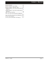


Section 3
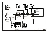
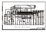
Electrical schematic . . . . . . . . . . . . . . . . . . . . . . . . . 3-3
Electrical schematic, Auto stabiliser . . . . . . . . . . . . 3-4
Electrical schematic, Lombardini diesel . . . . . . . . . 3-5
Automatic stabiliser control box assembly before SN
NZ051001 . . . . . . . . . . . . . . . . . . . . . . . . . . . . . . . 3-7
Automatic stabiliser control box assembly after SN
NZ051001 . . . . . . . . . . . . . . . . . . . . . . . . . . . . . . . 3-8
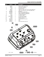
Upper control box assembly . . . . . . . . . . . . . . . . . . 3-9
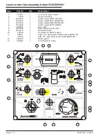
Lower control box assembly before SN NZ050901
. . . . . . . . . . . . . . . . . . . . . . . . . . . . . . . . . . . . . . 3-10
Lower control box assembly from SN NZ050901 . 3-11
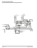
AC motor option drawing . . . . . . . . . . . . . . . . . . . . 3-12
AC motor option with 240VAC outlet drawing. . . . 3-13
MHP13/35 – 12431B
page 3 - 1
Section 3. - Electrical
Summary of Contents for MHP1335
Page 6: ......
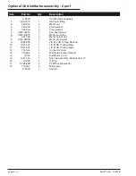
Page 24: ...page 1 2 MHP13 35 12431B ...
Page 34: ......
Page 41: ......
Page 56: ......
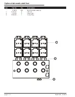
Page 58: ...page 2 2 MHP13 35 12431B ...
Page 72: ......
Page 74: ...Page 3 4 Electrical schematic Auto stabiliser ...
Page 76: ......
Page 84: ......
Page 96: ......
Page 106: ......